
Service Manual
Page 1
MAIN Electrical Parts List 7. Block Diagrams 8. Flow Chart of Troubleshooting 10. Specification 3. Exploded View/Disassembly and Assembly Instructions 6. Array course control 5. PCB Diagrams 9. Operation Instruction and Installation 4. Reference data GSM TELEPHONE SGH-D900i GSM TELEPHONE CONTENTS 1. Safety Precautions 2.
MAIN Electrical Parts List 7. Block Diagrams 8. Flow Chart of Troubleshooting 10. Specification 3. Exploded View/Disassembly and Assembly Instructions 6. Array course control 5. PCB Diagrams 9. Operation Instruction and Installation 4. Reference data GSM TELEPHONE SGH-D900i GSM TELEPHONE CONTENTS 1. Safety Precautions 2.

Service Manual
Page 3
...condition of connecting Test Pack and tuning on SEC System. 1. Take specially care of tuning or test, because specificity of cellular phone is sensitive for surrounding interference(RF noise). ● Be careful to use a kind of magnetic object or tool, because performance... by the influence of battery charger is dangerous when tuning ON/OFF PBA and Connector after disassembling charger. ● Don't use a standard screwdriver when you disassemble this rules. 1-1 SAMSUNG Proprietary-Contents may change other material than replacement registered on . ● Take specially care of...
...condition of connecting Test Pack and tuning on SEC System. 1. Take specially care of tuning or test, because specificity of cellular phone is sensitive for surrounding interference(RF noise). ● Be careful to use a kind of magnetic object or tool, because performance... by the influence of battery charger is dangerous when tuning ON/OFF PBA and Connector after disassembling charger. ● Don't use a standard screwdriver when you disassemble this rules. 1-1 SAMSUNG Proprietary-Contents may change other material than replacement registered on . ● Take specially care of...

Service Manual
Page 15
5. Exploded View/Disassembly&Assembly Instructions 5-1. Cellular phone Exploded View QMW01 QSC21 QSC20 QAN06 QKP01 QFU01 QME01 QKP02 QCA01 QSP02 QLC01 QPC01 QFL01 QCR67 QSC05 QSC06 QHI01 QVK01 QVO01 QCR67 QCR67 QIF01 QFR01 QSD01 QMI03 QMP01 QAN02 QCK01 QRE01 QCR67 QSC13 QSC14 QBA01 QRE05 QBA00 5-2 SAMSUNG Proprietary-Contents may change without notice This Document can not be used without Samsung's authorization
5. Exploded View/Disassembly&Assembly Instructions 5-1. Cellular phone Exploded View QMW01 QSC21 QSC20 QAN06 QKP01 QFU01 QME01 QKP02 QCA01 QSP02 QLC01 QPC01 QFL01 QCR67 QSC05 QSC06 QHI01 QVK01 QVO01 QCR67 QCR67 QIF01 QFR01 QSD01 QMI03 QMP01 QAN02 QCK01 QRE01 QCR67 QSC13 QSC14 QBA01 QRE05 QBA00 5-2 SAMSUNG Proprietary-Contents may change without notice This Document can not be used without Samsung's authorization

Service Manual
Page 16
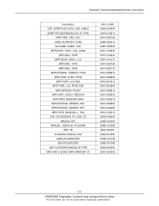
Cellular phone Parts list Design LOC QAN02 QAN06 QBA00 QBA01 QCA01 QCK01 QCR67 QCR67 QCR67 QCR67 QFL01...KEYPAD-(SER/XBA) ASSY KEYPAD-SUB(EU/XBA) MEA-LCD MODULE KIT(D900I) UNIT-KEY FPCB RMO-RUBBER MIC HOLDER PBA MAIN-SGHD900I ASSY COVER-MAIN WINDOW MEA-SLIDER FPCB KIT(D900I) ASSY CASE-REAR PMO-REAR DECO RMO-COVER SLIDE SCREW L RMO...-07232C GH73-07743C GH72-31668C GH72-31670C GH72-31738C GH59-03347A GH59-03265A GH72-31742A 5-2 SAMSUNG Proprietary-Contents may change without notice This Document can not be used without Samsung's authorization Exploded View/Disassembly&Assembly Instructions 5-2.
Cellular phone Parts list Design LOC QAN02 QAN06 QBA00 QBA01 QCA01 QCK01 QCR67 QCR67 QCR67 QCR67 QFL01...KEYPAD-(SER/XBA) ASSY KEYPAD-SUB(EU/XBA) MEA-LCD MODULE KIT(D900I) UNIT-KEY FPCB RMO-RUBBER MIC HOLDER PBA MAIN-SGHD900I ASSY COVER-MAIN WINDOW MEA-SLIDER FPCB KIT(D900I) ASSY CASE-REAR PMO-REAR DECO RMO-COVER SLIDE SCREW L RMO...-07232C GH73-07743C GH72-31668C GH72-31670C GH72-31738C GH59-03347A GH59-03265A GH72-31742A 5-2 SAMSUNG Proprietary-Contents may change without notice This Document can not be used without Samsung's authorization Exploded View/Disassembly&Assembly Instructions 5-2.
Service Manual
Page 17
Exploded View/Disassembly&Assembly Instructions Description CBF INTERFACE-DATA LINK CABLE ADAPTOR-SGHE690,BLK,EU,A_TYPE MPR-TAPE SIDE KEY LABEL(R)-WATER SOAK AS-DOME SHEET SVC MPR-...-25307A GH74-25689A GH74-25689A GH74-14051A GH46-00406A GH68-04336A GH68-14238A 6902-000634 GH69-04708A GH68-14312B GH69-05179B GH59-04029A GH74-26156A 5-3 SAMSUNG Proprietary-Contents may change without notice This Document can not be used without...
Exploded View/Disassembly&Assembly Instructions Description CBF INTERFACE-DATA LINK CABLE ADAPTOR-SGHE690,BLK,EU,A_TYPE MPR-TAPE SIDE KEY LABEL(R)-WATER SOAK AS-DOME SHEET SVC MPR-...-25307A GH74-25689A GH74-25689A GH74-14051A GH46-00406A GH68-04336A GH68-14238A 6902-000634 GH69-04708A GH68-14312B GH69-05179B GH59-04029A GH74-26156A 5-3 SAMSUNG Proprietary-Contents may change without notice This Document can not be used without...

Service Manual
Page 18
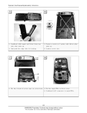
... Instructions 5-3-1. Make the space between rear cover and front cover using assembly stick. 2. And then widen space with moving slide. Remove 2 screw caps. 2. Exploded View/Disassembly&Assembly Instructions 5-3. Loosen a screw this six point form Rear. 1. Upside down the main PBA with hand and separate 2 parts. 3 4 1. Open 2 covers. (Blue) 3. Open the LCD...
... Instructions 5-3-1. Make the space between rear cover and front cover using assembly stick. 2. And then widen space with moving slide. Remove 2 screw caps. 2. Exploded View/Disassembly&Assembly Instructions 5-3. Loosen a screw this six point form Rear. 1. Upside down the main PBA with hand and separate 2 parts. 3 4 1. Open 2 covers. (Blue) 3. Open the LCD...

Service Manual
Page 19
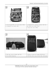
Remove the insulation tape. 2. Open the slide. (Slide up) 2. Make the space between slide upper and slide lower using assembly stick. 2. And then widen space with pinset. 1. Remove the 4 screw caps with hand and separate 2 parts. 1. Loosen a screw 4 point form Lower. 7 8 1. And separate LCD connector from sub-PBA. 5-5 SAMSUNG Proprietary-Contents may change without notice This Document can not be used without Samsung's authorization Exploded View/Disassembly&Assembly Instructions 5 6 1.
Remove the insulation tape. 2. Open the slide. (Slide up) 2. Make the space between slide upper and slide lower using assembly stick. 2. And then widen space with pinset. 1. Remove the 4 screw caps with hand and separate 2 parts. 1. Loosen a screw 4 point form Lower. 7 8 1. And separate LCD connector from sub-PBA. 5-5 SAMSUNG Proprietary-Contents may change without notice This Document can not be used without Samsung's authorization Exploded View/Disassembly&Assembly Instructions 5 6 1.

Service Manual
Page 20
Separate LCD module from slide upper. Separate sub-PBA from slide upper using 4 white points. 5-6 SAMSUNG Proprietary-Contents may change without notice This Document can not be used without Samsung's authorization And then caution the hook. 2. Exploded View/Disassembly&Assembly Instructions 9 10 1. Separate Camera connector from sub-PBA and speaker module and camera from slide upper. 1.
Separate LCD module from slide upper. Separate sub-PBA from slide upper using 4 white points. 5-6 SAMSUNG Proprietary-Contents may change without notice This Document can not be used without Samsung's authorization And then caution the hook. 2. Exploded View/Disassembly&Assembly Instructions 9 10 1. Separate Camera connector from sub-PBA and speaker module and camera from slide upper. 1.

Service Manual
Page 21
... line ※ Folding position 1. And combined camera connector to sub-PBA 2. Assembly 1 Exploded View/Disassembly&Assembly Instructions 2 1. And put insulation tape on connector. 5-7 SAMSUNG Proprietary-Contents may change without notice This Document can not be used without Samsung's authorization And put the camera at slide upper. (Red) accoding to main window and put...
... line ※ Folding position 1. And combined camera connector to sub-PBA 2. Assembly 1 Exploded View/Disassembly&Assembly Instructions 2 1. And put insulation tape on connector. 5-7 SAMSUNG Proprietary-Contents may change without notice This Document can not be used without Samsung's authorization And put the camera at slide upper. (Red) accoding to main window and put...
Service Manual
Page 22
Caution screw size. 7 8 1. Combined LCD connector to main-PBA. 5-8 SAMSUNG Proprietary-Contents may change without notice This Document can not be used without Samsung's authorization Combined slide upper and lower from top side after slide up . 2. Put the 2 kind of screw caps on front cover. 2. Fasten a screw at 4 points with driver after slide up . 2. Put the main-PBA on screw hole. 1. And push the edge side for locking. 1. Exploded View/Disassembly&Assembly Instructions 5 6 1.4*2.3 1.4*3.5 1.
Caution screw size. 7 8 1. Combined LCD connector to main-PBA. 5-8 SAMSUNG Proprietary-Contents may change without notice This Document can not be used without Samsung's authorization Combined slide upper and lower from top side after slide up . 2. Put the 2 kind of screw caps on front cover. 2. Fasten a screw at 4 points with driver after slide up . 2. Put the main-PBA on screw hole. 1. And push the edge side for locking. 1. Exploded View/Disassembly&Assembly Instructions 5 6 1.4*2.3 1.4*3.5 1.
Service Manual
Page 23
Put the screw cap on below hole with driver. 2. Close the cover. (Blue) 11 12 1. Combined Key connector and put side key and camera key.(Violet, Red) 2. Fasten a screw at 6 points with pinset 5-9 SAMSUNG Proprietary-Contents may change without notice This Document can not be used without Samsung's authorization Exploded View/Disassembly&Assembly Instructions 9 10 1. Put rear cover on 4 screw hole. (Blue) 2. Be careful losing key. 1. Locking the one hook. (Rec) 1. Put the main-PBA on Assay and lock. 2.
Put the screw cap on below hole with driver. 2. Close the cover. (Blue) 11 12 1. Combined Key connector and put side key and camera key.(Violet, Red) 2. Fasten a screw at 6 points with pinset 5-9 SAMSUNG Proprietary-Contents may change without notice This Document can not be used without Samsung's authorization Exploded View/Disassembly&Assembly Instructions 9 10 1. Put rear cover on 4 screw hole. (Blue) 2. Be careful losing key. 1. Locking the one hook. (Rec) 1. Put the main-PBA on Assay and lock. 2.

Service Manual
Page 24
Exploded View/Disassembly&Assembly Instructions 5-10 SAMSUNG Proprietary-Contents may change without notice This Document can not be used without Samsung's authorization
Exploded View/Disassembly&Assembly Instructions 5-10 SAMSUNG Proprietary-Contents may change without notice This Document can not be used without Samsung's authorization


