User Manual (ENGLISH)
Page 3
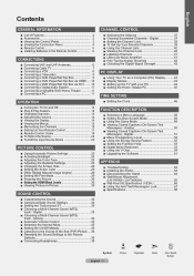
...Noise Reduction 53 Using the V-Chip 54 Upgrading the Software 61 Appendix Troubleshooting 62 Installing the Stand 64 Disconnecting the Stand 64 Wall-Mount Adjustment (LN-T4042H ,LN-T4642H 65 Wall Mount Kit Specifications ( VESA 66 Using the Anti-Theft Kensington Lock 67 ... Panel 3 Viewing the Connection Panel 4 Remote Control 5 Installing Batteries in the Remote Control 6 Connections Connecting VHF and UHF Antennas 6 Connecting Cable TV 7 Connecting a VCR 8 Connecting a Camcorder 9 Connecting a DVD Player/Set-Top Box 9 Connecting a DVD Player/Set-Top Box via HDMI.........
...Noise Reduction 53 Using the V-Chip 54 Upgrading the Software 61 Appendix Troubleshooting 62 Installing the Stand 64 Disconnecting the Stand 64 Wall-Mount Adjustment (LN-T4042H ,LN-T4642H 65 Wall Mount Kit Specifications ( VESA 66 Using the Anti-Theft Kensington Lock 67 ... Panel 3 Viewing the Connection Panel 4 Remote Control 5 Installing Batteries in the Remote Control 6 Connections Connecting VHF and UHF Antennas 6 Connecting Cable TV 7 Connecting a VCR 8 Connecting a Camcorder 9 Connecting a DVD Player/Set-Top Box 9 Connecting a DVD Player/Set-Top Box via HDMI.........
User Manual (ENGLISH)
Page 4
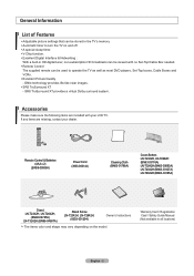
...are included with no Set-Top/Cable Box needed. Remote Control The supplied remote can be used to operate the TV as well as most DVD players, Set-Top boxes, Cable Boxes and VCRs. Excellent Picture Quality - General ...00598A) Power Cord (3903-000144) Cleaning Cloth (BN63-01798A) Cover-Bottom LN-T2342H, LN-T2642H (BN63-03176A) LN-T3242H (BN63-03093A) LN-T4042H (BN63-03127A) LN-T4642H (BN63-03185A) Stand LN-T2342H, LN-T2642H, (BN96-04745A) LN-T3242H (BN96-04697A) Stand Screw LN-T2342H, LN-T2642H, (6002-001294) Owner's Instructions The items color and shape may vary...
...are included with no Set-Top/Cable Box needed. Remote Control The supplied remote can be used to operate the TV as well as most DVD players, Set-Top boxes, Cable Boxes and VCRs. Excellent Picture Quality - General ...00598A) Power Cord (3903-000144) Cleaning Cloth (BN63-01798A) Cover-Bottom LN-T2342H, LN-T2642H (BN63-03176A) LN-T3242H (BN63-03093A) LN-T4042H (BN63-03127A) LN-T4642H (BN63-03185A) Stand LN-T2342H, LN-T2642H, (BN96-04745A) LN-T3242H (BN96-04697A) Stand Screw LN-T2342H, LN-T2642H, (6002-001294) Owner's Instructions The items color and shape may vary...
User Manual (ENGLISH)
Page 5
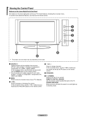
...vary depending on the model. 1 SOURCE Toggles between all the available input sources (TV, AV1, AV2, S-Video 1, S-Video 2, Component1, Component2, PC, HDMI1, HDMI2, HDMI3) In the on-screen menu, use this spot on and lights up in stand-by mode. In the on-screen menu, use the CH buttons as you would... button as you would use the ◄ and ► buttons on -screen menu of the Panel The buttons on the lower-right panel control your TV's features. 3 + VOL Press to increase or decrease the volume. POWER INDICATOR Blinks and turns off . Viewing the Control Panel Buttons on the Lower-Right ...
...vary depending on the model. 1 SOURCE Toggles between all the available input sources (TV, AV1, AV2, S-Video 1, S-Video 2, Component1, Component2, PC, HDMI1, HDMI2, HDMI3) In the on-screen menu, use this spot on and lights up in stand-by mode. In the on-screen menu, use the CH buttons as you would... button as you would use the ◄ and ► buttons on -screen menu of the Panel The buttons on the lower-right panel control your TV's features. 3 + VOL Press to increase or decrease the volume. POWER INDICATOR Blinks and turns off . Viewing the Control Panel Buttons on the Lower-Right ...
User Manual (ENGLISH)
Page 66
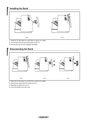
Put the stand into the hole indicated and tighten. < 3 > Disconnecting the Stand < 2 > < 3 > 1. Installing the Stand < 2 > 1. Insert screw into the hole at the bottom of the TV. 3. Cover the bottom hole with a cap. < 4 > English - 64 Remove four screws from the TV. 4. Place the TV face down on a soft cloth or cushion on a table. 2. Separate the stand from the back of the TV. 3. Place the TV face down on a soft cloth or cushion on a table. 2.
Put the stand into the hole indicated and tighten. < 3 > Disconnecting the Stand < 2 > < 3 > 1. Installing the Stand < 2 > 1. Insert screw into the hole at the bottom of the TV. 3. Cover the bottom hole with a cap. < 4 > English - 64 Remove four screws from the TV. 4. Place the TV face down on a soft cloth or cushion on a table. 2. Separate the stand from the back of the TV. 3. Place the TV face down on a soft cloth or cushion on a table. 2.


