Service Manual
Page 2
... their respective owners. All other trademarks are trademarks of Samsung Electronics Co., Ltd. 920NW Service Manual First edition July 20067. All rights reserved. This manual may not, in whole or in Korea. Macintosh, Power Macintosh are the property of Samsung Electronics Co., Ltd. Printed in part, be copied, photocopied, reproduced, translated, or converted to...
... their respective owners. All other trademarks are trademarks of Samsung Electronics Co., Ltd. 920NW Service Manual First edition July 20067. All rights reserved. This manual may not, in whole or in Korea. Macintosh, Power Macintosh are the property of Samsung Electronics Co., Ltd. Printed in part, be copied, photocopied, reproduced, translated, or converted to...
Service Manual
Page 3
... and Adjustments ...3-1 3-1 Required Equipment ...3-1 3-2 Automatic Color Adjustment ...3-1 3-3 DDC EDID Data Input ...3-1 3-4 How to execute DDC ...3-2 3-5 How to execute MCU Code ...3-3 4. Wiring Diagram ...8-1 Exploded View and Parts List ...5-1 6. Contents 1. Troubleshooting ...4-1 4-1 Common Acknowledge ...4-1 4-2 No Power & Power LED Off ...4-2 4-3 DC output voltage is unstable ...4-3 4-4 Output power is unstable ...4-4 4-5 Backlight can't be turned on ...4-5 4-6 Black...
... and Adjustments ...3-1 3-1 Required Equipment ...3-1 3-2 Automatic Color Adjustment ...3-1 3-3 DDC EDID Data Input ...3-1 3-4 How to execute DDC ...3-2 3-5 How to execute MCU Code ...3-3 4. Wiring Diagram ...8-1 Exploded View and Parts List ...5-1 6. Contents 1. Troubleshooting ...4-1 4-1 Common Acknowledge ...4-1 4-2 No Power & Power LED Off ...4-2 4-3 DC output voltage is unstable ...4-3 4-4 Output power is unstable ...4-4 4-5 Backlight can't be turned on ...4-5 4-6 Black...
Service Manual
Page 4
PCB Diagram ...12-1 13. Circuit Descriptions ...13-1 13-1 Overall Block Structure ...13-1 13-2 IP BOARD part(Inverter Part) ...13-4 14. Reference Infomation ...14-1 14-1 Technical Terms ...14-1 14-2 Connecting the monitor ...14-3 14-3 Pin Assignments ...14-4 14-4 Timing Chart ...14-5 14-5 Preset Timing Modes ...14-6 14-6 Panel ... 9-1 INPUT ...9-1 9-2 DCINPUT ...9-2 9-3 SCALER ...9-3 9-4 POWER ...9-4 9-5 POWER ...9-5 9-6 KEYPAD ...9-6 10. Operating Instructions and Installation ...10-1 10-1 Front ...10-1 10-2 Rear ...10-2 10-3 Monitor Assembly ...10-3 10-4 Attaching a Base ...10-4 11.
PCB Diagram ...12-1 13. Circuit Descriptions ...13-1 13-1 Overall Block Structure ...13-1 13-2 IP BOARD part(Inverter Part) ...13-4 14. Reference Infomation ...14-1 14-1 Technical Terms ...14-1 14-2 Connecting the monitor ...14-3 14-3 Pin Assignments ...14-4 14-4 Timing Chart ...14-5 14-5 Preset Timing Modes ...14-6 14-6 Panel ... 9-1 INPUT ...9-1 9-2 DCINPUT ...9-2 9-3 SCALER ...9-3 9-4 POWER ...9-4 9-5 POWER ...9-5 9-6 KEYPAD ...9-6 10. Operating Instructions and Installation ...10-1 10-1 Front ...10-1 10-2 Rear ...10-2 10-3 Monitor Assembly ...10-3 10-4 Attaching a Base ...10-4 11.
Service Manual
Page 6
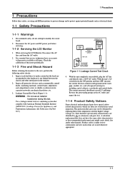
... power jack before servicing. 1-1-2 Servicing the LCD Monitor 1. Use a leakage current tester or a metering system that have an accurate voltage meter available at all exposed metal parts, including: metal cabinets, screwheads and control shafts. Parts that complies with components rated for Appliances), and... Test Circuit 4. The protection they give may not be obtained by on schematics and parts lists. With the unit's AC switch first in the monitor. 2. When servicing the LCD Monitor, Disconnect the AC line cord from visual inspection. Check the calibration of this test...
... power jack before servicing. 1-1-2 Servicing the LCD Monitor 1. Use a leakage current tester or a metering system that have an accurate voltage meter available at all exposed metal parts, including: metal cabinets, screwheads and control shafts. Parts that complies with components rated for Appliances), and... Test Circuit 4. The protection they give may not be obtained by on schematics and parts lists. With the unit's AC switch first in the monitor. 2. When servicing the LCD Monitor, Disconnect the AC line cord from visual inspection. Check the calibration of this test...
Service Manual
Page 7
...the blades of a replacement ESD, touch the protective material to the chassis or circuit and observe all such elements to the monitor. 2. After servicing, always check that are ready to install it on a conductive surface such as aluminum foil to prevent ...solder removal device. Reinstall all other conductive materials. 7. Check the insulation between each blade of the AC plug and accessible conductive parts (examples: metal panels, input terminals and earphone jacks). 5. Minimize body motions when handling unpackaged replacement ESDs. Before servicing units covered...
...the blades of a replacement ESD, touch the protective material to the chassis or circuit and observe all such elements to the monitor. 2. After servicing, always check that are ready to install it on a conductive surface such as aluminum foil to prevent ...solder removal device. Reinstall all other conductive materials. 7. Check the insulation between each blade of the AC plug and accessible conductive parts (examples: metal panels, input terminals and earphone jacks). 5. Minimize body motions when handling unpackaged replacement ESDs. Before servicing units covered...
Service Manual
Page 18
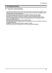
...the condition of specification, the picture may appears abnormally. - color is an abnormal color that means the problem happen in the analog circuit part, if only some scale appears abnormal color that the U105, U106 and U103 these three components also changed to the new I/F board ... LCM is out of Windows shut down pattern. - If you change the interface board, be sure that stand the problem happen in the digital circuit part. - If you confirm the R.G.B. If brightness uneven, repairs Inverter circuit or change panel. 4-1 If you check the H/V position, please use the crosshatch...
...the condition of specification, the picture may appears abnormally. - color is an abnormal color that means the problem happen in the analog circuit part, if only some scale appears abnormal color that the U105, U106 and U103 these three components also changed to the new I/F board ... LCM is out of Windows shut down pattern. - If you change the interface board, be sure that stand the problem happen in the digital circuit part. - If you confirm the R.G.B. If brightness uneven, repairs Inverter circuit or change panel. 4-1 If you check the H/V position, please use the crosshatch...

Service Manual
Page 26
samsung.co.kr 5-1 Exploded View M0215 6 Exploded View & Parts List 7140200053 7140100097 5-1 sec. 5 Exploded View and Parts List -You can search for updated part codes through ITSELF web site. URL : http://itself.
samsung.co.kr 5-1 Exploded View M0215 6 Exploded View & Parts List 7140200053 7140100097 5-1 sec. 5 Exploded View and Parts List -You can search for updated part codes through ITSELF web site. URL : http://itself.
Service Manual
Page 28
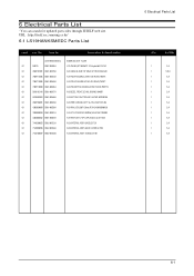
URL : http://itself.sec.samsung.co.kr/ 6-1 LS19HANKSM/EDC Parts List Level Loc. No. Description & Specification LS19HANKSM/EDC 920NW SILVER, TCO99 0.1 M0215 BN07-00406A LCD-PANEL;MT190AWO1 V2,Haydn,6bit FRC,42 0.1 4530101001 BN81-00270A A/S-CABLE;D-SUB 15P MALE 6FT,ROHS,BLACK/ ...;BLK 6FT UL/CSA,10A/125V,453 0.1 4303030009 BN81-00550A A/S-HRN LVDS;30P,120mm,ROHS,430303000920 0.1 7030000059 BN81-00551A A/S-KIT ACCESSORY;920NW,US,LE1961,703000 0.1 4303008002 BN81-00555A A/S-HRN ASS'Y;2*4P to 5P,265mm,UL1571#28 0.1 7140200053 BN82-00152A A/S MATERIAL ASSY-BASE;LE1729...
URL : http://itself.sec.samsung.co.kr/ 6-1 LS19HANKSM/EDC Parts List Level Loc. No. Description & Specification LS19HANKSM/EDC 920NW SILVER, TCO99 0.1 M0215 BN07-00406A LCD-PANEL;MT190AWO1 V2,Haydn,6bit FRC,42 0.1 4530101001 BN81-00270A A/S-CABLE;D-SUB 15P MALE 6FT,ROHS,BLACK/ ...;BLK 6FT UL/CSA,10A/125V,453 0.1 4303030009 BN81-00550A A/S-HRN LVDS;30P,120mm,ROHS,430303000920 0.1 7030000059 BN81-00551A A/S-KIT ACCESSORY;920NW,US,LE1961,703000 0.1 4303008002 BN81-00555A A/S-HRN ASS'Y;2*4P to 5P,265mm,UL1571#28 0.1 7140200053 BN82-00152A A/S MATERIAL ASSY-BASE;LE1729...

Service Manual
Page 29
6 Electrical Parts List Memo 6-2
6 Electrical Parts List Memo 6-2

Service Manual
Page 55
13 Circuit Descriptions 13-1-2 Main board Parts 1. The IP board receives 5V and outputs 1.8 or 3.3V that converts DC rated voltage/current to high ones necessary for DC to which key is a ...
13 Circuit Descriptions 13-1-2 Main board Parts 1. The IP board receives 5V and outputs 1.8 or 3.3V that converts DC rated voltage/current to high ones necessary for DC to which key is a ...


