Service Manual
Page 4
Operating Instructions and Installation ...10-1 10-1 Front ...10-1 10-2 Rear ...10-2 10-3 Monitor Assembly ...10-3 10-4 Attaching a Base ...10-4 11. Disassembly and Reassembly ...11-1 11-1 Disassembly Block ...11-1 11-2 Reassembly ...11-4 12. Circuit Descriptions ...13-1 13-1 Overall Block Structure ...13-1 13-2 IP BOARD part(Inverter Part) ...13-4 14. PCB Diagram ...12-1 ...
Operating Instructions and Installation ...10-1 10-1 Front ...10-1 10-2 Rear ...10-2 10-3 Monitor Assembly ...10-3 10-4 Attaching a Base ...10-4 11. Disassembly and Reassembly ...11-1 11-1 Disassembly Block ...11-1 11-2 Reassembly ...11-4 12. Circuit Descriptions ...13-1 13-1 Overall Block Structure ...13-1 13-2 IP BOARD part(Inverter Part) ...13-4 14. PCB Diagram ...12-1 ...
Service Manual
Page 48
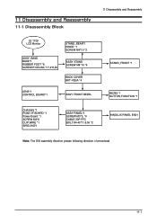
11 Disassembly and Reassembly 11-1 Disassembly Block 11 Disassembly and Reassembly LE 1729 LCD Monitor ASSY, BASE BASE*1 RUBBER FOOT *6 SCREW.P.CROSS,T.T-4*8,Zn STAND_REAR*1 HINGE *1 SCREW M4*10 *3 ASSY STAND SCREW M4*10 *4 BACK COVER BKT-VESA *4 LENS*1 CONTROL BOARD*1 ASSY FRONT BEZEL STAND_FRONT *1 BEZEL*1 BUTTON,FUNCTION *1 CHASSIS *1 PCBA I/F BOARD *1 Power Board *1 SCREW M3*6 CLIP,WIRE *1 SHIELING*1 ASSY PANEL*1 SCREW M3*5, *4 CABLE 30P FFC BOLT,#4-40*11.8,Ni *2 INNOLUX PANEL EN01 Note: The DIS assembly direction please following direction of arrowhead 11-1
11 Disassembly and Reassembly 11-1 Disassembly Block 11 Disassembly and Reassembly LE 1729 LCD Monitor ASSY, BASE BASE*1 RUBBER FOOT *6 SCREW.P.CROSS,T.T-4*8,Zn STAND_REAR*1 HINGE *1 SCREW M4*10 *3 ASSY STAND SCREW M4*10 *4 BACK COVER BKT-VESA *4 LENS*1 CONTROL BOARD*1 ASSY FRONT BEZEL STAND_FRONT *1 BEZEL*1 BUTTON,FUNCTION *1 CHASSIS *1 PCBA I/F BOARD *1 Power Board *1 SCREW M3*6 CLIP,WIRE *1 SHIELING*1 ASSY PANEL*1 SCREW M3*5, *4 CABLE 30P FFC BOLT,#4-40*11.8,Ni *2 INNOLUX PANEL EN01 Note: The DIS assembly direction please following direction of arrowhead 11-1

Service Manual
Page 49
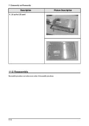
Remove the stand and front coler 11-2 11 Disassembly and Reassembly Description 1. Remove 4 screw from the stand Picture Description 2.
Remove the stand and front coler 11-2 11 Disassembly and Reassembly Description 1. Remove 4 screw from the stand Picture Description 2.

Service Manual
Page 50
Lift the back cover and use the jig to remove the shield lamp. 11 Disassembly and Reassembly Picture Description 4. Lift up the shield and disconnect LVDS cables 11-3 Description 3. Disconnect cables 5.
Lift the back cover and use the jig to remove the shield lamp. 11 Disassembly and Reassembly Picture Description 4. Lift up the shield and disconnect LVDS cables 11-3 Description 3. Disconnect cables 5.
Service Manual
Page 51
Lift up the LCD panel Picture Description 11-2 Reassembly Reassembly procedures are in the reverse order of disassembly procedures. 11-4 11 Disassembly and Reassembly 설 명 사D진esc설ri명ption 6.
Lift up the LCD panel Picture Description 11-2 Reassembly Reassembly procedures are in the reverse order of disassembly procedures. 11-4 11 Disassembly and Reassembly 설 명 사D진esc설ri명ption 6.

User Guide
Page 2
The images here are for an extended period of time, set your computer to DPMS. If using a screen saver, set it to active screen mode. Prohibited Do not disassemble Do not touch Important to read and understand at all cases (or countries). Notational Failure to follow directions noted by this symbol could result in all times Disconnect the plug from the outlet Ground to prevent an electric shock Power When not used for reference only, and are not applicable in bodily harm or damage to the equipment.
The images here are for an extended period of time, set your computer to DPMS. If using a screen saver, set it to active screen mode. Prohibited Do not disassemble Do not touch Important to read and understand at all cases (or countries). Notational Failure to follow directions noted by this symbol could result in all times Disconnect the plug from the outlet Ground to prevent an electric shock Power When not used for reference only, and are not applicable in bodily harm or damage to the equipment.

