Service Manual
Page 3
Block Diagram ...7-1 7-1 Power tree ...7-1 7-2 Mainboard part ...7-2 7-3 IP Board Part(SMPS Part) ...7-2 7-4 IP BOARD part(Inverter Part) ...7-3 8. Troubleshooting ...4-1 4-1 Common Acknowledge ...4-1 4-2 No Power & Power LED Off ...4-2 4-3 DC output voltage is unstable ...4-3 4-4 Output power is unstable ...4-4 4-5 Backlight can't be turned on ...4-5 4-6 Black Screen and backlight ...
Block Diagram ...7-1 7-1 Power tree ...7-1 7-2 Mainboard part ...7-2 7-3 IP Board Part(SMPS Part) ...7-2 7-4 IP BOARD part(Inverter Part) ...7-3 8. Troubleshooting ...4-1 4-1 Common Acknowledge ...4-1 4-2 No Power & Power LED Off ...4-2 4-3 DC output voltage is unstable ...4-3 4-4 Output power is unstable ...4-4 4-5 Backlight can't be turned on ...4-5 4-6 Black Screen and backlight ...
Service Manual
Page 18
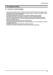
... changed to the new I/F board because there was program inside. If not, please re-write EDID or upload firmware into Flash memory via VGA Cable. - 4 Troubleshooting 4 Troubleshooting 4-1 Common Acknowledge - color is out of Windows shut down pattern. -
... changed to the new I/F board because there was program inside. If not, please re-write EDID or upload firmware into Flash memory via VGA Cable. - 4 Troubleshooting 4 Troubleshooting 4-1 Common Acknowledge - color is out of Windows shut down pattern. -

Service Manual
Page 19
4 Troubleshooting 4-2 No Power & Power LED Off No power Check primary rectifier voltage Check circuit if short Check IC802, C805, T801 Check pin6 of IC802 voltage about 12V Check F801, P801, RT,801,D801 Check C810,D803,C807 Check pin2 of IC802 voltage about 3V Check primary OVP, OLP and secondary feedback, Check pin1 of IC802 voltage is voltage is below 1V Check R811, R810, R809, R808,R814 END 4-2
4 Troubleshooting 4-2 No Power & Power LED Off No power Check primary rectifier voltage Check circuit if short Check IC802, C805, T801 Check pin6 of IC802 voltage about 12V Check F801, P801, RT,801,D801 Check C810,D803,C807 Check pin2 of IC802 voltage about 3V Check primary OVP, OLP and secondary feedback, Check pin1 of IC802 voltage is voltage is below 1V Check R811, R810, R809, R808,R814 END 4-2

Service Manual
Page 20
4-3 Output power is unstable Unstable power 4 Troubleshooting Check sampling Circuit Check the R pin voltage of IC803 about 2.5V Check R822, R823, R824 Check the C pin voltage of IC803 if 3V Change R822, R823, R824 Change IC803 Check pin1 of IC802 voltage is 5.8V Check R819, R820 Check R818, D804, C807 if short Change R818 Check pin1 of IC802 voltage about 3V Change R808, R809, R810, R811 END 4-3
4-3 Output power is unstable Unstable power 4 Troubleshooting Check sampling Circuit Check the R pin voltage of IC803 about 2.5V Check R822, R823, R824 Check the C pin voltage of IC803 if 3V Change R822, R823, R824 Change IC803 Check pin1 of IC802 voltage is 5.8V Check R819, R820 Check R818, D804, C807 if short Change R818 Check pin1 of IC802 voltage about 3V Change R808, R809, R810, R811 END 4-3

Service Manual
Page 21
4 Troubleshooting 4-4 Backlight can't be turned on No backlight Yes LED lamp is OK Yes Is there 14V voltage on pin 3,4 of T501, T502 Yes Is there ...
4 Troubleshooting 4-4 Backlight can't be turned on No backlight Yes LED lamp is OK Yes Is there 14V voltage on pin 3,4 of T501, T502 Yes Is there ...

Service Manual
Page 22
4-5 Black Screen and backlight turn on Black Screen 4 Troubleshooting Check power supply: Pin1, 2 of CN102 Yes Check pin34, 51, 66, and 82 Of U105 Yes Check pin12, 68, 97 and 117 Of U103 Yes Check Reset (pin19) Of U103 Yes Check Crystal: Pin32, Pin33 Of U103 Yes Check CCFLEnable (pin20) of U103 No MCU Fail No Power Fail No Check FB103 And U102 No Check FB105 And U106 No Check C149, R157 No Check: X1, C147, C148 Yes Check pin5 of Yes CN102 Inverter Fail No Check R127, Q101, R125, R126 4-5
4-5 Black Screen and backlight turn on Black Screen 4 Troubleshooting Check power supply: Pin1, 2 of CN102 Yes Check pin34, 51, 66, and 82 Of U105 Yes Check pin12, 68, 97 and 117 Of U103 Yes Check Reset (pin19) Of U103 Yes Check Crystal: Pin32, Pin33 Of U103 Yes Check CCFLEnable (pin20) of U103 No MCU Fail No Power Fail No Check FB103 And U102 No Check FB105 And U106 No Check C149, R157 No Check: X1, C147, C148 Yes Check pin5 of Yes CN102 Inverter Fail No Check R127, Q101, R125, R126 4-5

Service Manual
Page 23
Yes No Check R134, R176, Q102, Q105 Check LVDS Yes Signals No Check the HW No Reset Of U103 pin19 Yes Check the pins Of U103 Panel Fail Check C149 R157 END 4-6 No Check Panel Enable Of U103 (pin75) is High? 4 Troubleshooting 4-6 White Screen White Screen LVDS Cable Yes Reinsert No Workmanship Change LVDS Yes Cable LVDS Cable NG No Check VLCD Is 5V?
Yes No Check R134, R176, Q102, Q105 Check LVDS Yes Signals No Check the HW No Reset Of U103 pin19 Yes Check the pins Of U103 Panel Fail Check C149 R157 END 4-6 No Check Panel Enable Of U103 (pin75) is High? 4 Troubleshooting 4-6 White Screen White Screen LVDS Cable Yes Reinsert No Workmanship Change LVDS Yes Cable LVDS Cable NG No Check VLCD Is 5V?

Service Manual
Page 24
4-8 Bad Screen Bad Screen LVDS Cable Yes Reinsert No Change LVDS Yes Cable No Check Yes Crystal:Pin32, Pin33 of U103 Yes Check the No communication Of U103 and U104 Yes Check the pins of U103 and U104 4 Troubleshooting Workmanship LVDS Cable NG Check :X1, C147, C148 Check: SDO, SCZ, SCK, SDI, Reset 4-7
4-8 Bad Screen Bad Screen LVDS Cable Yes Reinsert No Change LVDS Yes Cable No Check Yes Crystal:Pin32, Pin33 of U103 Yes Check the No communication Of U103 and U104 Yes Check the pins of U103 and U104 4 Troubleshooting Workmanship LVDS Cable NG Check :X1, C147, C148 Check: SDO, SCZ, SCK, SDI, Reset 4-7
