
Quick Guide (ENGLISH)
Page 3
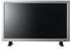
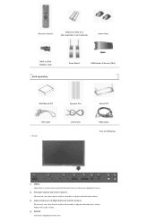
... all locations) Cover-Hole BNC to RCA Adaptor Jack Sold separately Semi Stand USB Holder & Screw (1EA) Wall Mount KIT Speaker Set DVI Cable Front LAN Cable Stand KIT BNC Cable Your LCD Display 1) MENU Opens the on-screen menu and exits from the menu or closes the adjustment menu. 2) Navigate buttons (Up...
... all locations) Cover-Hole BNC to RCA Adaptor Jack Sold separately Semi Stand USB Holder & Screw (1EA) Wall Mount KIT Speaker Set DVI Cable Front LAN Cable Stand KIT BNC Cable Your LCD Display 1) MENU Opens the on-screen menu and exits from the menu or closes the adjustment menu. 2) Navigate buttons (Up...

Quick Guide (ENGLISH)
Page 5
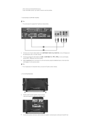
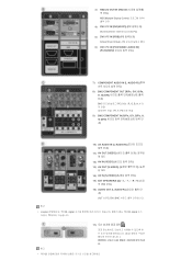
...) (Input) 13) AV OUT [S-VIDEO] (S-VIDEO Connection Terminal): S-VIDEO mode (Output) 14) AV IN [S-VIDEO] (S-VIDEO Connection Terminal) (Input) 15) EXT SPEAKER(8 Ω)[- - R - +] (EXT Speaker Connection Terminal) 16) AUDIO OUT [L-AUDIO-R] (LCD Display Audio Connection Terminal (Output)) AUDIO OUT is no degradation or signal source, up to DVI-D) - DVI mode (Digital PC) 5) DVI / PC...
...) (Input) 13) AV OUT [S-VIDEO] (S-VIDEO Connection Terminal): S-VIDEO mode (Output) 14) AV IN [S-VIDEO] (S-VIDEO Connection Terminal) (Input) 15) EXT SPEAKER(8 Ω)[- - R - +] (EXT Speaker Connection Terminal) 16) AUDIO OUT [L-AUDIO-R] (LCD Display Audio Connection Terminal (Output)) AUDIO OUT is no degradation or signal source, up to DVI-D) - DVI mode (Digital PC) 5) DVI / PC...

Quick Guide (ENGLISH)
Page 10
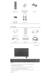
... X 2) (Not available in all locations) Cover-Hole BNC to RCA Adaptor Jack Sold separately Semi Stand Wall Mount KIT Speaker Set DVI Cable Front LAN Cable Stand KIT BNC Cable Your LCD Display 1) MENU Opens the on-screen menu and exits from the menu or closes the adjustment menu. 2) Navigate buttons (Up-Down...
... X 2) (Not available in all locations) Cover-Hole BNC to RCA Adaptor Jack Sold separately Semi Stand Wall Mount KIT Speaker Set DVI Cable Front LAN Cable Stand KIT BNC Cable Your LCD Display 1) MENU Opens the on-screen menu and exits from the menu or closes the adjustment menu. 2) Navigate buttons (Up-Down...

Quick Guide (ENGLISH)
Page 12
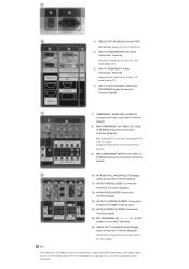
... PR, Y, PB ports 9) BNC/COMPONENT IN [R/PR, G/Y, B/PB, H, V] (BNC/Component Connection Terminal (Input)) 10) AV AUDIO IN [L-AUDIO-R] (LCD Display Audio Connection Terminal (Input)) 11) AV OUT [VIDEO] (VIDEO Connection Terminal): AV mode (Output) 12) AV IN [VIDEO] (VIDEO Connection Terminal) (Input...): S-VIDEO mode (Output) 14) AV IN [S-VIDEO] (S-VIDEO Connection Terminal) (Input) 15) EXT SPEAKER(8 Ω)[- - R - +] (EXT Speaker Connection Terminal) 16) AUDIO OUT [L-AUDIO-R] (LCD Display Audio Connection Terminal (Output)) AUDIO OUT is no degradation or signal source, up to DVI-D) -
... PR, Y, PB ports 9) BNC/COMPONENT IN [R/PR, G/Y, B/PB, H, V] (BNC/Component Connection Terminal (Input)) 10) AV AUDIO IN [L-AUDIO-R] (LCD Display Audio Connection Terminal (Input)) 11) AV OUT [VIDEO] (VIDEO Connection Terminal): AV mode (Output) 12) AV IN [VIDEO] (VIDEO Connection Terminal) (Input...): S-VIDEO mode (Output) 14) AV IN [S-VIDEO] (S-VIDEO Connection Terminal) (Input) 15) EXT SPEAKER(8 Ω)[- - R - +] (EXT Speaker Connection Terminal) 16) AUDIO OUT [L-AUDIO-R] (LCD Display Audio Connection Terminal (Output)) AUDIO OUT is no degradation or signal source, up to DVI-D) -
Quick Guide (ENGLISH)
Page 21
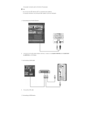
... a set of the SET and Connecting Speakers 1) Fasten the SET and the speaker using the screws. * Mount the speaker set of Component video, see your camcorder is stereo, you need to a DTV Set Top Box using the SOURCE button on the front of the LCD Display or on the back of audio cables ...between the COMPONENT AUDIO IN [L-AUDIO-R] on the LCD Display and the AUDIO OUT jacks on the Set Top Box. 2) Connect a Component cable between the speaker connection jack on the remote control. Note •...
... a set of the SET and Connecting Speakers 1) Fasten the SET and the speaker using the screws. * Mount the speaker set of Component video, see your camcorder is stereo, you need to a DTV Set Top Box using the SOURCE button on the front of the LCD Display or on the back of audio cables ...between the COMPONENT AUDIO IN [L-AUDIO-R] on the LCD Display and the AUDIO OUT jacks on the Set Top Box. 2) Connect a Component cable between the speaker connection jack on the remote control. Note •...
Quick Guide (ENGLISH)
Page 22
Connecting a LAN Cable 1) Connect the LAN cable. The speaker-bracket for connecting the SET speaker my become damaged. Connecting a USB device the speaker connection jack on the back of audio cables between the AUX L, R jacks on the AUDIO SYSTEM and the AUDIO OUT [L-AUDIO-R] on LCD Display. Note • Do not move the SET while the SET is connected to an Audio System 1) Connect a set of the speaker. Connecting to the speakers.
Connecting a LAN Cable 1) Connect the LAN cable. The speaker-bracket for connecting the SET speaker my become damaged. Connecting a USB device the speaker connection jack on the back of audio cables between the AUX L, R jacks on the AUDIO SYSTEM and the AUDIO OUT [L-AUDIO-R] on LCD Display. Note • Do not move the SET while the SET is connected to an Audio System 1) Connect a set of the speaker. Connecting to the speakers.

Quick Guide (ENGLISH)
Page 30
... a DTV Set Top Box using the screws. * Mount the speaker set without the speaker stand. 2) Connect the speaker connection cable between the speaker connection jack on the back of the LCD Display or on the front of the SET and Connecting Speakers 1) Fasten the SET and the speaker using the SOURCE button on the remote control. PR, Y, PB...
... a DTV Set Top Box using the screws. * Mount the speaker set without the speaker stand. 2) Connect the speaker connection cable between the speaker connection jack on the back of the LCD Display or on the front of the SET and Connecting Speakers 1) Fasten the SET and the speaker using the SOURCE button on the remote control. PR, Y, PB...

Quick Guide (ENGLISH)
Page 31
Note • Do not move the SET while the SET is connected to an Audio System 1) Connect a set of the speaker. ALL Right Reserved the speaker connection jack on the back of audio cables between the AUX L, R jacks on the AUDIO SYSTEM and the AUDIO OUT [L-AUDIO-R] on LCD Display. © 1995~2007 SAMSUNG. The speaker-bracket for connecting the SET speaker my become damaged. Connecting to the speakers.
Note • Do not move the SET while the SET is connected to an Audio System 1) Connect a set of the speaker. ALL Right Reserved the speaker connection jack on the back of audio cables between the AUX L, R jacks on the AUDIO SYSTEM and the AUDIO OUT [L-AUDIO-R] on LCD Display. © 1995~2007 SAMSUNG. The speaker-bracket for connecting the SET speaker my become damaged. Connecting to the speakers.
Quick Guide (KOREAN)
Page 5
... IN [VIDEO 13) AV OUT [S-VIDEO] (S S-영 상 모드 14) AV IN [S-VIDEO] (S 15) EXT SPEAKER(8 Ω)[- - L - +, - - DVI PC) 5) DVI / PC IN [RGB] (PC D-Sub(15 pin D-Sub) - 3) RS232C OUT/IN (RS232C MDC(Multiple Display Control 4) DVI / PC IN [DVI(HDCP)] (PC DVI-D to DVI-D - R 16) AUDIO OUT [L-AUDIO-R 자) OUT...
... IN [VIDEO 13) AV OUT [S-VIDEO] (S S-영 상 모드 14) AV IN [S-VIDEO] (S 15) EXT SPEAKER(8 Ω)[- - L - +, - - DVI PC) 5) DVI / PC IN [RGB] (PC D-Sub(15 pin D-Sub) - 3) RS232C OUT/IN (RS232C MDC(Multiple Display Control 4) DVI / PC IN [DVI(HDCP)] (PC DVI-D to DVI-D - R 16) AUDIO OUT [L-AUDIO-R 자) OUT...
Quick Guide (KOREAN)
Page 12
3) RS232C OUT/IN (RS232C MDC(Multiple Display Control 4) DVI / PC IN [DVI(HDCP)] (PC DVI-D to DVI-D - L - +, - - PC PC) 6) DVI / PC IN [PC/DVI/BNC AUDIO IN] (PC/DVI/BNC 7) COMPONENT AUDIO ... AUDIO IN [L-AUDIO-R 11) AV OUT [VIDEO 12) AV IN [VIDEO 13) AV OUT [S-VIDEO] (S S-영 상 모드 14) AV IN [S-VIDEO] (S 15) EXT SPEAKER(8 Ω)[- - DVI PC) 5) DVI / PC IN [RGB] (PC D-Sub(15 pin D-Sub) - R 16) AUDIO OUT [L-AUDIO-R 자) OUT 는 PC, DVI, BNC 참고 •...
3) RS232C OUT/IN (RS232C MDC(Multiple Display Control 4) DVI / PC IN [DVI(HDCP)] (PC DVI-D to DVI-D - L - +, - - PC PC) 6) DVI / PC IN [PC/DVI/BNC AUDIO IN] (PC/DVI/BNC 7) COMPONENT AUDIO ... AUDIO IN [L-AUDIO-R 11) AV OUT [VIDEO 12) AV IN [VIDEO 13) AV OUT [S-VIDEO] (S S-영 상 모드 14) AV IN [S-VIDEO] (S 15) EXT SPEAKER(8 Ω)[- - DVI PC) 5) DVI / PC IN [RGB] (PC D-Sub(15 pin D-Sub) - R 16) AUDIO OUT [L-AUDIO-R 자) OUT 는 PC, DVI, BNC 참고 •...
User Manual (ENGLISH)
Page 12
... all locations) Cover-Hole BNC to RCA Adaptor Jack Sold separately Semi Stand USB Holder & Screw (1EA) Wall Mount KIT Speaker Set DVI Cable Front LAN Cable Stand KIT BNC Cable Your LCD Display 1) MENU Opens the on-screen menu and exits from the menu or closes the adjustment menu. 2) Navigate buttons (Up...
... all locations) Cover-Hole BNC to RCA Adaptor Jack Sold separately Semi Stand USB Holder & Screw (1EA) Wall Mount KIT Speaker Set DVI Cable Front LAN Cable Stand KIT BNC Cable Your LCD Display 1) MENU Opens the on-screen menu and exits from the menu or closes the adjustment menu. 2) Navigate buttons (Up...

User Manual (ENGLISH)
Page 14
... the terminal for sound output of LCD Display s that can be connected to DVI-D) - R - +] (EXT Speaker Connection Terminal) 16) AUDIO OUT [L-AUDIO-R] (LCD Display Audio Connection Terminal (Output)) AUDIO OUT is no degradation or signal source, up to ten LCD Displays can be connected. PC mode (Analog..., Y, PB ports 9) BNC/COMPONENT IN [R/PR, G/Y, B/PB, H, V] (BNC/Component Connection Terminal (Input)) 10) AV AUDIO IN [L-AUDIO-R] (LCD Display Audio Connection Terminal (Input)) 11) AV OUT [VIDEO] (VIDEO Connection Terminal): AV mode (Output) 12) AV IN [VIDEO] (VIDEO Connection Terminal) ...
... the terminal for sound output of LCD Display s that can be connected to DVI-D) - R - +] (EXT Speaker Connection Terminal) 16) AUDIO OUT [L-AUDIO-R] (LCD Display Audio Connection Terminal (Output)) AUDIO OUT is no degradation or signal source, up to ten LCD Displays can be connected. PC mode (Analog..., Y, PB ports 9) BNC/COMPONENT IN [R/PR, G/Y, B/PB, H, V] (BNC/Component Connection Terminal (Input)) 10) AV AUDIO IN [L-AUDIO-R] (LCD Display Audio Connection Terminal (Input)) 11) AV OUT [VIDEO] (VIDEO Connection Terminal): AV mode (Output) 12) AV IN [VIDEO] (VIDEO Connection Terminal) ...
User Manual (ENGLISH)
Page 19
... X 2) (Not available in all locations) Cover-Hole BNC to RCA Adaptor Jack Sold separately Semi Stand Wall Mount KIT Speaker Set DVI Cable Front LAN Cable Stand KIT BNC Cable Your LCD Display 1) MENU Opens the on-screen menu and exits from the menu or closes the adjustment menu. 2) Navigate buttons (Up-Down...
... X 2) (Not available in all locations) Cover-Hole BNC to RCA Adaptor Jack Sold separately Semi Stand Wall Mount KIT Speaker Set DVI Cable Front LAN Cable Stand KIT BNC Cable Your LCD Display 1) MENU Opens the on-screen menu and exits from the menu or closes the adjustment menu. 2) Navigate buttons (Up-Down...
User Manual (ENGLISH)
Page 21
...R - +] (EXT Speaker Connection Terminal) 16) AUDIO OUT [L-AUDIO-R] (LCD Display Audio Connection Terminal (Output)) AUDIO OUT is no degradation or signal source, up to ten LCD Displays can be connected. With cables where there is the terminal for sound output of LCD Display s that can be ... PR, Y, PB ports 9) BNC/COMPONENT IN [R/PR, G/Y, B/PB, H, V] (BNC/Component Connection Terminal (Input)) 10) AV AUDIO IN [L-AUDIO-R] (LCD Display Audio Connection Terminal (Input)) 11) AV OUT [VIDEO] (VIDEO Connection Terminal): AV mode (Output) 12) AV IN [VIDEO] (VIDEO Connection Terminal) (Input...
...R - +] (EXT Speaker Connection Terminal) 16) AUDIO OUT [L-AUDIO-R] (LCD Display Audio Connection Terminal (Output)) AUDIO OUT is no degradation or signal source, up to ten LCD Displays can be connected. With cables where there is the terminal for sound output of LCD Display s that can be ... PR, Y, PB ports 9) BNC/COMPONENT IN [R/PR, G/Y, B/PB, H, V] (BNC/Component Connection Terminal (Input)) 10) AV AUDIO IN [L-AUDIO-R] (LCD Display Audio Connection Terminal (Input)) 11) AV OUT [VIDEO] (VIDEO Connection Terminal): AV mode (Output) 12) AV IN [VIDEO] (VIDEO Connection Terminal) (Input...
User Manual (ENGLISH)
Page 25
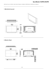
SyncMaster 400PXn/400PX Mechanical Lay-out | Monitor Head | Stand | Speaker | Installation VESA Bracket | Wall Bracket Installation 1. Monitor Head Mechanical Lay-out Dodatak 2.
SyncMaster 400PXn/400PX Mechanical Lay-out | Monitor Head | Stand | Speaker | Installation VESA Bracket | Wall Bracket Installation 1. Monitor Head Mechanical Lay-out Dodatak 2.

User Manual (ENGLISH)
Page 26
Speaker 5. z Purchasing VESA Bracket and Installation Information : Please contact your order is not responsible for any product damage or any injury caused by installation at customer's discretion. After your nearest Samsung Distributor to place an order. z Samsung is placed, installation professionals will visit you and install the bracket. Stand 4. Installation VESA Bracket z When installing VESA, make sure to move the LCD Monitor. 3. z At least 2 persons are needed in order to comply with the international VESA standards. Dimensions
Speaker 5. z Purchasing VESA Bracket and Installation Information : Please contact your order is not responsible for any product damage or any injury caused by installation at customer's discretion. After your nearest Samsung Distributor to place an order. z Samsung is placed, installation professionals will visit you and install the bracket. Stand 4. Installation VESA Bracket z When installing VESA, make sure to move the LCD Monitor. 3. z At least 2 persons are needed in order to comply with the international VESA standards. Dimensions
User Manual (ENGLISH)
Page 31
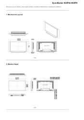
SyncMaster 460PXn/460PX Mechanical Lay-out | Monitor Head | Stand | Speaker | Installation VESA Bracket | Wall Bracket Installation 1. Monitor Head Mechanical Lay-out Dodatak 2.
SyncMaster 460PXn/460PX Mechanical Lay-out | Monitor Head | Stand | Speaker | Installation VESA Bracket | Wall Bracket Installation 1. Monitor Head Mechanical Lay-out Dodatak 2.

User Manual (ENGLISH)
Page 32
z Samsung is placed, installation professionals will visit you and install the bracket. 3. Stand 4. z At least 2 persons are needed in order to comply with the international VESA standards. Speaker 5. After your nearest Samsung Distributor to place an order. Dimensions z Purchasing VESA Bracket and Installation Information : Please contact your order is not responsible for any product damage or any injury caused by installation at customer's discretion. Installation VESA Bracket z When installing VESA, make sure to move the LCD Monitor.
z Samsung is placed, installation professionals will visit you and install the bracket. 3. Stand 4. z At least 2 persons are needed in order to comply with the international VESA standards. Speaker 5. After your nearest Samsung Distributor to place an order. Dimensions z Purchasing VESA Bracket and Installation Information : Please contact your order is not responsible for any product damage or any injury caused by installation at customer's discretion. Installation VESA Bracket z When installing VESA, make sure to move the LCD Monitor.

User Manual (ENGLISH)
Page 42
...connect a set of two cables. PR, Y, PB port on the LCD Display and the PR, Y, PB jacks on the Set Top Box. 3) Select Component for a typical Set Top Box are shown below. 1) Connect a set without the speaker stand. 2) Connect the speaker connection cable between the BNC / COMPONENT IN - Note • For...for the connection to a DTV Set Top Box using the screws. * Mount the speaker set of the SET and Connecting Speakers 1) Fasten the SET and the speaker using the SOURCE button on the front of the LCD Display or on the back of audio cables between the COMPONENT AUDIO IN [L-AUDIO-R] on...
...connect a set of two cables. PR, Y, PB port on the LCD Display and the PR, Y, PB jacks on the Set Top Box. 3) Select Component for a typical Set Top Box are shown below. 1) Connect a set without the speaker stand. 2) Connect the speaker connection cable between the BNC / COMPONENT IN - Note • For...for the connection to a DTV Set Top Box using the screws. * Mount the speaker set of the SET and Connecting Speakers 1) Fasten the SET and the speaker using the SOURCE button on the front of the LCD Display or on the back of audio cables between the COMPONENT AUDIO IN [L-AUDIO-R] on...

User Manual (ENGLISH)
Page 43
Note • Do not move the SET while the SET is connected to an Audio System 1) Connect a set of the speaker. The speaker-bracket for connecting the SET speaker my become damaged. Connecting a LAN Cable 1) Connect the LAN cable. Connecting a USB device Connecting to the speakers. the speaker connection jack on the back of audio cables between the AUX L, R jacks on the AUDIO SYSTEM and the AUDIO OUT [L-AUDIO-R] on LCD Display.
Note • Do not move the SET while the SET is connected to an Audio System 1) Connect a set of the speaker. The speaker-bracket for connecting the SET speaker my become damaged. Connecting a LAN Cable 1) Connect the LAN cable. Connecting a USB device Connecting to the speakers. the speaker connection jack on the back of audio cables between the AUX L, R jacks on the AUDIO SYSTEM and the AUDIO OUT [L-AUDIO-R] on LCD Display.


