
Quick Guide (ENGLISH)
Page 3
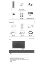
... available in all locations) Cover-Hole BNC to RCA Adaptor Jack Sold separately Semi Stand USB Holder & Screw (1EA) Wall Mount KIT Speaker Set DVI Cable Front LAN Cable Stand KIT BNC Cable Your LCD Display 1) MENU Opens the on-screen menu and exits from the menu or closes the adjustment menu. 2) Navigate buttons...
... available in all locations) Cover-Hole BNC to RCA Adaptor Jack Sold separately Semi Stand USB Holder & Screw (1EA) Wall Mount KIT Speaker Set DVI Cable Front LAN Cable Stand KIT BNC Cable Your LCD Display 1) MENU Opens the on-screen menu and exits from the menu or closes the adjustment menu. 2) Navigate buttons...

Quick Guide (ENGLISH)
Page 10
... Batteries (AAA X 2) (Not available in all locations) Cover-Hole BNC to RCA Adaptor Jack Sold separately Semi Stand Wall Mount KIT Speaker Set DVI Cable Front LAN Cable Stand KIT BNC Cable Your LCD Display 1) MENU Opens the on-screen menu and exits from the menu or closes the adjustment menu. 2) Navigate buttons (Up...
... Batteries (AAA X 2) (Not available in all locations) Cover-Hole BNC to RCA Adaptor Jack Sold separately Semi Stand Wall Mount KIT Speaker Set DVI Cable Front LAN Cable Stand KIT BNC Cable Your LCD Display 1) MENU Opens the on-screen menu and exits from the menu or closes the adjustment menu. 2) Navigate buttons (Up...

Quick Guide (ENGLISH)
Page 16
...folded backwards. 1) A 'Cover-Protector' is inserted. SyncMaster 400PXn/460PXn Select Language Main Page Model Safety Instructions Introduction Connections Installing the Stand KIT Connecting the LCD Display Using the Software Adjusting the LCD Display Troubleshooting Specifications Information Appendix The color and appearance of ...the wall mount kit. 2) Set up the left and right stands respectively. 3) Insert the stand into the hole indicated and tighten it. (M4 x L15) Caution Caution Samsung Electronics will not be used to protect the hole at the bottom of the LCD Display. Insert...
...folded backwards. 1) A 'Cover-Protector' is inserted. SyncMaster 400PXn/460PXn Select Language Main Page Model Safety Instructions Introduction Connections Installing the Stand KIT Connecting the LCD Display Using the Software Adjusting the LCD Display Troubleshooting Specifications Information Appendix The color and appearance of ...the wall mount kit. 2) Set up the left and right stands respectively. 3) Insert the stand into the hole indicated and tighten it. (M4 x L15) Caution Caution Samsung Electronics will not be used to protect the hole at the bottom of the LCD Display. Insert...

Quick Guide (ENGLISH)
Page 17
...using the 'Cover-Hole' when attaching the wall mount kit. 2) Ensure that the parts are inserted in the right direction and in the right place. (M4 × L15) 3) Insert the stand into the hole indicated and tighten it. (M4 × L15) Connecting the LCD Display Using a Power cord with Earth In ...angle. Connecting to wire the earth lead in advance. When un-wiring the earth lead, make sure to the User Controls under Adjusting Your LCD Display. For detailed information on . Under no circumstances use the product as your computer can be connected to protect the hole at the bottom ...
...using the 'Cover-Hole' when attaching the wall mount kit. 2) Ensure that the parts are inserted in the right direction and in the right place. (M4 × L15) 3) Insert the stand into the hole indicated and tighten it. (M4 × L15) Connecting the LCD Display Using a Power cord with Earth In ...angle. Connecting to wire the earth lead in advance. When un-wiring the earth lead, make sure to the User Controls under Adjusting Your LCD Display. For detailed information on . Under no circumstances use the product as your computer can be connected to protect the hole at the bottom ...

Quick Guide (ENGLISH)
Page 25
...LCD Display , where the stand is inserted. SyncMaster 400PX/460PX Select Language Main Page Model Safety Instructions Introduction Connections Installing the Stand KIT Connecting the LCD Display Using the Software Adjusting the LCD Display... Troubleshooting Specifications Information Appendix The color and appearance of the product may vary depending on the model, and the product specifications are subject to change without prior notice for damages caused by using the 'Cover-Hole' when attaching the wall mount...Caution Samsung ...
...LCD Display , where the stand is inserted. SyncMaster 400PX/460PX Select Language Main Page Model Safety Instructions Introduction Connections Installing the Stand KIT Connecting the LCD Display Using the Software Adjusting the LCD Display... Troubleshooting Specifications Information Appendix The color and appearance of the product may vary depending on the model, and the product specifications are subject to change without prior notice for damages caused by using the 'Cover-Hole' when attaching the wall mount...Caution Samsung ...

Quick Guide (ENGLISH)
Page 26
...attaching the provided Semi Stand or Stand KIT (sold separately) 1) A 'Cover-Protector' is used to protect the hole at the bottom of the LCD Display. 4) Insert the screw into the hole at the bottom of failure, the earth lead may cause electric shock. For detailed information on . When... of the LCD Display , where the stand is inserted. This stand is designed for placing something on connecting AV input devices, refer to disconnect the AC power in advance. The company is not responsible for any problem caused when using the 'Cover-Hole' when attaching the wall mount kit. 2)...
...attaching the provided Semi Stand or Stand KIT (sold separately) 1) A 'Cover-Protector' is used to protect the hole at the bottom of the LCD Display. 4) Insert the screw into the hole at the bottom of failure, the earth lead may cause electric shock. For detailed information on . When... of the LCD Display , where the stand is inserted. This stand is designed for placing something on connecting AV input devices, refer to disconnect the AC power in advance. The company is not responsible for any problem caused when using the 'Cover-Hole' when attaching the wall mount kit. 2)...
User Manual (ENGLISH)
Page 5
... of the bracket must be done by unqualified personnel may damage the LCD Display. The installation of the TFT-LCD screen, wipe with a smooth cloth. z Always use the mounting device specified in injury. z This may cause an increase in a... shortened component life and degraded performance. z The plastic packaging (bag) may damage the TFT-LCD surface. z This may cause suffocation if children play with it away from the wall (more than 10 cm / 4 inches) for ventilation purposes. Do not place the LCD Display...
... of the bracket must be done by unqualified personnel may damage the LCD Display. The installation of the TFT-LCD screen, wipe with a smooth cloth. z Always use the mounting device specified in injury. z This may cause an increase in a... shortened component life and degraded performance. z The plastic packaging (bag) may damage the TFT-LCD surface. z This may cause suffocation if children play with it away from the wall (more than 10 cm / 4 inches) for ventilation purposes. Do not place the LCD Display...
User Manual (ENGLISH)
Page 12
... available in all locations) Cover-Hole BNC to RCA Adaptor Jack Sold separately Semi Stand USB Holder & Screw (1EA) Wall Mount KIT Speaker Set DVI Cable Front LAN Cable Stand KIT BNC Cable Your LCD Display 1) MENU Opens the on-screen menu and exits from the menu or closes the adjustment menu. 2) Navigate buttons...
... available in all locations) Cover-Hole BNC to RCA Adaptor Jack Sold separately Semi Stand USB Holder & Screw (1EA) Wall Mount KIT Speaker Set DVI Cable Front LAN Cable Stand KIT BNC Cable Your LCD Display 1) MENU Opens the on-screen menu and exits from the menu or closes the adjustment menu. 2) Navigate buttons...
User Manual (ENGLISH)
Page 19
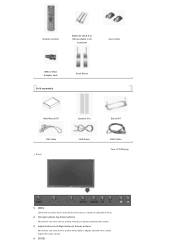
... Batteries (AAA X 2) (Not available in all locations) Cover-Hole BNC to RCA Adaptor Jack Sold separately Semi Stand Wall Mount KIT Speaker Set DVI Cable Front LAN Cable Stand KIT BNC Cable Your LCD Display 1) MENU Opens the on-screen menu and exits from the menu or closes the adjustment menu. 2) Navigate buttons (Up...
... Batteries (AAA X 2) (Not available in all locations) Cover-Hole BNC to RCA Adaptor Jack Sold separately Semi Stand Wall Mount KIT Speaker Set DVI Cable Front LAN Cable Stand KIT BNC Cable Your LCD Display 1) MENU Opens the on-screen menu and exits from the menu or closes the adjustment menu. 2) Navigate buttons (Up...

User Manual (ENGLISH)
Page 27
... and 8 to customers when the installation is for installing on cement walls. When done, mount the wall bracket on plaster or wood. Wall Bracket Installation z Contact a technician for any damages to the product or harm to 12 mm length. 6. z Samsung Electronics is not responsible for installing the wall bracket. Hinge (Right) For securing the bracket on...
... and 8 to customers when the installation is for installing on cement walls. When done, mount the wall bracket on plaster or wood. Wall Bracket Installation z Contact a technician for any damages to the product or harm to 12 mm length. 6. z Samsung Electronics is not responsible for installing the wall bracket. Hinge (Right) For securing the bracket on...

User Manual (ENGLISH)
Page 28
... if the length between the two locking holes Check the installation diagram and mark the drill points on the wall bracket to adjust the length. Use the correct one. A. Fix each of the brackets and hinge holes to drill holes deeper than 35 mm. Use ... the plastic hanger and the screw are two hinges(left and right). Match each anchor in the corresponding hole. If the length is correct. To mount the product on the wall bracket The shape of the product may vary depending on the model. (The assemblies of the 4screws on the...
... if the length between the two locking holes Check the installation diagram and mark the drill points on the wall bracket to adjust the length. Use the correct one. A. Fix each of the brackets and hinge holes to drill holes deeper than 35 mm. Use ... the plastic hanger and the screw are two hinges(left and right). Match each anchor in the corresponding hole. If the length is correct. To mount the product on the wall bracket The shape of the product may vary depending on the model. (The assemblies of the 4screws on the...

User Manual (ENGLISH)
Page 29
Remove the 4 screws on the back of the product. Insert the screw B into the corresponding bracket holes (1). A. Mount the product on the wall. Make sure the wall bracket is securely fixed to the wall, or the product may not stay in the holes. 3. Tighten the 4 screws in step 2 (plastic hanger + ... hold the product to the bracket. Be careful when installing the product on the bracket as fingers can be caught in place after installation. Wall Bracket C. Then place the product(2) so that it is firmly fixed to the bracket. Monitor B. Remove safety pin (3) and insert the ...
Remove the 4 screws on the back of the product. Insert the screw B into the corresponding bracket holes (1). A. Mount the product on the wall. Make sure the wall bracket is securely fixed to the wall, or the product may not stay in the holes. 3. Tighten the 4 screws in step 2 (plastic hanger + ... hold the product to the bracket. Be careful when installing the product on the bracket as fingers can be caught in place after installation. Wall Bracket C. Then place the product(2) so that it is firmly fixed to the bracket. Monitor B. Remove safety pin (3) and insert the ...

User Manual (ENGLISH)
Page 33
...Anchor (4) (11) (4) (11) Wall Bracket Assembly Insert and tighten the Captive Screw in the direction of 6 mm diameter and 8 to customers when the installation is for installing the wall bracket. z This product is done by the customer. A. z Samsung Electronics is not responsible for any damages ...to the product or harm to 12 mm length. 6. When done, mount the wall bracket on cement walls. Components Only use only machine...
...Anchor (4) (11) (4) (11) Wall Bracket Assembly Insert and tighten the Captive Screw in the direction of 6 mm diameter and 8 to customers when the installation is for installing the wall bracket. z This product is done by the customer. A. z Samsung Electronics is not responsible for any damages ...to the product or harm to 12 mm length. 6. When done, mount the wall bracket on cement walls. Components Only use only machine...

User Manual (ENGLISH)
Page 34
...installation diagram and mark the drill points on the model. (The assemblies of the 4screws on the wall bracket to drill holes deeper than 35 mm. A. Length between the two locking holes at the...some of the plastic hanger and the screw are two hinges(left and right). To mount the product on the wall bracket The shape of the brackets and hinge holes to the corresponding anchor holes and ...insert and tighten the 11 screws A. Fix each of the product may vary depending on the wall. Match each anchor in the corresponding hole. If the length is correct. Use the 5.0 mm bit...
...installation diagram and mark the drill points on the model. (The assemblies of the 4screws on the wall bracket to drill holes deeper than 35 mm. A. Length between the two locking holes at the...some of the plastic hanger and the screw are two hinges(left and right). To mount the product on the wall bracket The shape of the brackets and hinge holes to the corresponding anchor holes and ...insert and tighten the 11 screws A. Fix each of the product may vary depending on the wall. Match each anchor in the corresponding hole. If the length is correct. Use the 5.0 mm bit...

User Manual (ENGLISH)
Page 35
...the product. Then place the product(2) so that it is firmly fixed to -2°before installing it on the wall bracket and make sure it is securely fixed to the bracket. A. Wall Wall Bracket Angle Adjustment Adjust the bracket angle to the bracket. Remove the 4 screws on the bracket as fingers ...can be caught in the holes. 3. Monitor B. Insert the screw B into the corresponding bracket holes (1). Mount the product on the wall. Tighten the 4 screws in step 2 (plastic hanger + screw B)to the left and right plastic hangers...
...the product. Then place the product(2) so that it is firmly fixed to -2°before installing it on the wall bracket and make sure it is securely fixed to the bracket. A. Wall Wall Bracket Angle Adjustment Adjust the bracket angle to the bracket. Remove the 4 screws on the bracket as fingers ...can be caught in the holes. 3. Monitor B. Insert the screw B into the corresponding bracket holes (1). Mount the product on the wall. Tighten the 4 screws in step 2 (plastic hanger + screw B)to the left and right plastic hangers...
User Manual (ENGLISH)
Page 37
...supplied bolts should be responsible for reasons of the LCD Display. Caution Samsung Electronics will not be used to protect the hole at the bottom of performance enhancement. SyncMaster 400PXn/460PXn Select Language Main Page Model Safety Instructions...LCD Display Using the Software Adjusting the LCD Display Troubleshooting Specifications Information Appendix The color and appearance of the product may vary depending on the model, and the product specifications are subject to change without prior notice for damages caused by using the 'Cover-Hole' when attaching the wall mount...
...supplied bolts should be responsible for reasons of the LCD Display. Caution Samsung Electronics will not be used to protect the hole at the bottom of performance enhancement. SyncMaster 400PXn/460PXn Select Language Main Page Model Safety Instructions...LCD Display Using the Software Adjusting the LCD Display Troubleshooting Specifications Information Appendix The color and appearance of the product may vary depending on the model, and the product specifications are subject to change without prior notice for damages caused by using the 'Cover-Hole' when attaching the wall mount...

User Manual (ENGLISH)
Page 38
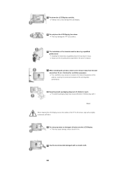
...attaching the provided Semi Stand or Stand KIT (sold separately) 1) A 'Cover-Protector' is used to protect the hole at the bottom of the LCD Display. 4) Insert the screw into the hole at the bottom of failure, the earth lead may cause electric shock. This stand is designed for placing ...using the 'Cover-Hole' when attaching the wall mount kit. 2) Ensure that the parts are inserted in the right direction and in the right place. (M4 × L15) 3) Insert the stand into the hole indicated and tighten it. (M4 × L15) Connecting the LCD Display Using a Power cord with Earth In ...
...attaching the provided Semi Stand or Stand KIT (sold separately) 1) A 'Cover-Protector' is used to protect the hole at the bottom of the LCD Display. 4) Insert the screw into the hole at the bottom of failure, the earth lead may cause electric shock. This stand is designed for placing ...using the 'Cover-Hole' when attaching the wall mount kit. 2) Ensure that the parts are inserted in the right direction and in the right place. (M4 × L15) 3) Insert the stand into the hole indicated and tighten it. (M4 × L15) Connecting the LCD Display Using a Power cord with Earth In ...
User Manual (ENGLISH)
Page 46
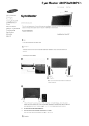
SyncMaster 400PX/460PX Select Language Main Page Model Safety Instructions Introduction Connections Installing the Stand KIT Connecting the LCD Display Using the Software Adjusting the LCD Display Troubleshooting Specifications Information Appendix The color and ...appearance of the product may vary depending on the model, and the product specifications are subject to change without prior notice for damages caused by using the 'Cover-Hole' when attaching the wall mount...
SyncMaster 400PX/460PX Select Language Main Page Model Safety Instructions Introduction Connections Installing the Stand KIT Connecting the LCD Display Using the Software Adjusting the LCD Display Troubleshooting Specifications Information Appendix The color and ...appearance of the product may vary depending on the model, and the product specifications are subject to change without prior notice for damages caused by using the 'Cover-Hole' when attaching the wall mount...
User Manual (ENGLISH)
Page 47
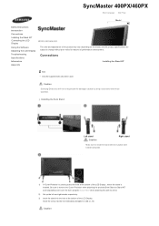
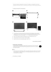
...(M4 × L15) Connecting the LCD Display Using a Power cord with Earth In the event of the LCD Display , where the stand is not responsible for adjusting the screen angle. This stand is designed for any problem caused when using the 'Cover-Hole' when attaching the wall mount kit. 2) Ensure that the parts... are inserted in the right direction and in correctly, before connecting the AC power. When un-wiring the earth lead, make sure to a Computer Be sure to protect the hole at the bottom of the LCD Display. 4) Insert the screw...
...(M4 × L15) Connecting the LCD Display Using a Power cord with Earth In the event of the LCD Display , where the stand is not responsible for adjusting the screen angle. This stand is designed for any problem caused when using the 'Cover-Hole' when attaching the wall mount kit. 2) Ensure that the parts... are inserted in the right direction and in correctly, before connecting the AC power. When un-wiring the earth lead, make sure to a Computer Be sure to protect the hole at the bottom of the LCD Display. 4) Insert the screw...


