
User Manual
Page 4
...the product. • Otherwise, this may result in serious harm (suffocation) if children play with it may result in fire due to the screen display. Install your product in fire. 3 Ensure that an authorized installation company installs the wall mount. • Otherwise, it in a badly ventilated ... person carrying it may result in damage to an increase in the in the discoloration and distortion of your monitor is a clearance of the TFT-LCD screen, wipe with a dry cloth. • Otherwise, it down , make sure to install the specified wall mount. When putting the product ...
...the product. • Otherwise, this may result in serious harm (suffocation) if children play with it may result in fire due to the screen display. Install your product in fire. 3 Ensure that an authorized installation company installs the wall mount. • Otherwise, it in a badly ventilated ... person carrying it may result in damage to an increase in the in the discoloration and distortion of your monitor is a clearance of the TFT-LCD screen, wipe with a dry cloth. • Otherwise, it down , make sure to install the specified wall mount. When putting the product ...
User Manual
Page 9
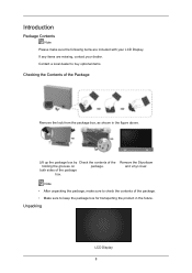
... sides of the holding the grooves on package. If any items are included with your dealer. Remove the Styrofoam and vinyl cover. Unpacking LCD Display 8 Lift up the package box by Check the contents of the package box. Note • After unpacking the package, make sure the... following items are missing, contact your LCD Display. Introduction Package Contents Note Please make sure to check the contents of the package. • Make sure to buy optional items. Checking the...
... sides of the holding the grooves on package. If any items are included with your dealer. Remove the Styrofoam and vinyl cover. Unpacking LCD Display 8 Lift up the package box by Check the contents of the package box. Note • After unpacking the package, make sure the... following items are missing, contact your LCD Display. Introduction Package Contents Note Please make sure to check the contents of the package. • Make sure to buy optional items. Checking the...
User Manual
Page 11
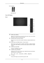
... that an external device is not on -screen menu and exits from one menu item to adjust volume. Sold separately Introduction Semi Stand KIT Your LCD Display Front MENU button [MENU] Opens the on the screen, press the button to another horizontally or adjusts selected menu values.
... that an external device is not on -screen menu and exits from one menu item to adjust volume. Sold separately Introduction Semi Stand KIT Your LCD Display Front MENU button [MENU] Opens the on the screen, press the button to another horizontally or adjusts selected menu values.
User Manual
Page 12
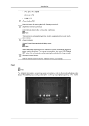
...under Setup. Remote Control Sensor Aim the remote control towards this button for turning the LCD Display on and off. For energy conservation, turn your LCD Display OFF when it unattended for further information regarding power saving functions. Power indicator Shows PowerSaver ... / HDMI • DVI / AV : PC • HDMI : PC Power button [ ] Use this spot on the LCD Display. Brightness Sensor (Optional) Automatically detects the surrounding brightness. The LCD Display 's configuration at the back may vary slightly depending on the models equipped with an auto brightness sensor.
...under Setup. Remote Control Sensor Aim the remote control towards this button for turning the LCD Display on and off. For energy conservation, turn your LCD Display OFF when it unattended for further information regarding power saving functions. Power indicator Shows PowerSaver ... / HDMI • DVI / AV : PC • HDMI : PC Power button [ ] Use this spot on the LCD Display. Brightness Sensor (Optional) Automatically detects the surrounding brightness. The LCD Display 's configuration at the back may vary slightly depending on the models equipped with an auto brightness sensor.
User Manual
Page 13
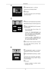
DVI OUT • Connect a monitor to BNC cable. AUDIOR] Connect the port of the LCD Display. PC mode (Analog PC) • Connect the [RGB/COMPONENT IN] port on the monitor to the COMPONENT port on the external device using the DSUB ... PC) DVI/RGB/HDMI AUDIO IN (PC/DVI/ HDMI Audio Connection Terminal (Input)) AV/COMPONENT AUDIO IN [L- RS232C OUT/IN (RS232C Serial PORT) MDC(Multiple Display Control) Program Port RGB / COMPONENT IN (PC Connection Terminal (Input)) • Use a D-Sub Cable (15 pin D-Sub) - R] port of the DVD, VCR (DVD / DTV Set...
DVI OUT • Connect a monitor to BNC cable. AUDIOR] Connect the port of the LCD Display. PC mode (Analog PC) • Connect the [RGB/COMPONENT IN] port on the monitor to the COMPONENT port on the external device using the DSUB ... PC) DVI/RGB/HDMI AUDIO IN (PC/DVI/ HDMI Audio Connection Terminal (Input)) AV/COMPONENT AUDIO IN [L- RS232C OUT/IN (RS232C Serial PORT) MDC(Multiple Display Control) Program Port RGB / COMPONENT IN (PC Connection Terminal (Input)) • Use a D-Sub Cable (15 pin D-Sub) - R] port of the DVD, VCR (DVD / DTV Set...
User Manual
Page 14
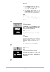
... Keyboard / Mouse, Mass Storage Device Compatible. 13 AV IN [VIDEO] Connect the [ VIDEO ] terminal of your monitor to the HDMI terminal of your LCD Display to the video output terminal of your digital output device using a HDMI cable. Up to HDMI cable. • DVI, HDMI and network signals sent via... the [DVI OUT] port are displayed on the product). AUDIO OUT Headphone/External speaker output terminal. Introduction • Connect the [DVI OUT] port on the monitor to the HDMI IN ...
... Keyboard / Mouse, Mass Storage Device Compatible. 13 AV IN [VIDEO] Connect the [ VIDEO ] terminal of your monitor to the HDMI terminal of your LCD Display to the video output terminal of your digital output device using a HDMI cable. Up to HDMI cable. • DVI, HDMI and network signals sent via... the [DVI OUT] port are displayed on the product). AUDIO OUT Headphone/External speaker output terminal. Introduction • Connect the [DVI OUT] port on the monitor to the HDMI IN ...
User Manual
Page 15
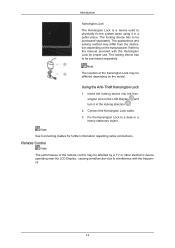
... the Kensington Lock cable. 3. Note See Connecting Cables for proper use. Insert the locking device into the Kensington slot on the LCD Display and turn it in the locking direction . 2. Fix the Kensington Lock to be different depending on the manufacturer. Introduction Kensington Lock... when using it in a public place. The locking device has to be affected by a TV or other electronic device operating near the LCD Display , causing a malfunction due to the manual provided with the frequency. 14 The appearance and locking method may be purchased separately. Using the...
... the Kensington Lock cable. 3. Note See Connecting Cables for proper use. Insert the locking device into the Kensington slot on the LCD Display and turn it in the locking direction . 2. Fix the Kensington Lock to be different depending on the manufacturer. Introduction Kensington Lock... when using it in a public place. The locking device has to be affected by a TV or other electronic device operating near the LCD Display , causing a malfunction due to the manual provided with the frequency. 14 The appearance and locking method may be purchased separately. Using the...

User Manual
Page 16
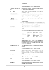
... the input signal SOURCE. This function does not work for this LCD Display. SOURCE 7. Turns the product Off. Electronic Program Guide (EPG) display. - OFF 3. The "-" button is only allowed for this LCD Display. DTV menu display - Number Buttons 4. TOOLS Turns the product On. Adjusts the ... function does not work for external devices that are connected to select Digital channels. Use to quickly select frequently used to the LCD Display at the time. D.MENU 8. Changing the SOURCE is used functions. 15 Introduction POWER OFF Number Buttons DEL + VOL - ...
... the input signal SOURCE. This function does not work for this LCD Display. SOURCE 7. Turns the product Off. Electronic Program Guide (EPG) display. - OFF 3. The "-" button is only allowed for this LCD Display. DTV menu display - Number Buttons 4. TOOLS Turns the product On. Adjusts the ... function does not work for external devices that are connected to select Digital channels. Use to quickly select frequently used to the LCD Display at the time. D.MENU 8. Changing the SOURCE is used functions. 15 Introduction POWER OFF Number Buttons DEL + VOL - ...
User Manual
Page 17
Current picture information is used to return to the immediately previous channel. - This function does not work for this LCD Display. This function does not work for this LCD Display. In TV mode, selects TV channels. - Up-Down Left-Right buttons 10. TV channels provide written information services via ... the audio output temporarily. The audio comes back on the remote control while watching TV. This function does not work for this LCD Display. TTX/MIX - Moves from the menu or closes the adjustment menu. 16 Press to add or delete channels and to store channels...
Current picture information is used to return to the immediately previous channel. - This function does not work for this LCD Display. This function does not work for this LCD Display. In TV mode, selects TV channels. - Up-Down Left-Right buttons 10. TV channels provide written information services via ... the audio output temporarily. The audio comes back on the remote control while watching TV. This function does not work for this LCD Display. TTX/MIX - Moves from the menu or closes the adjustment menu. 16 Press to add or delete channels and to store channels...
User Manual
Page 19
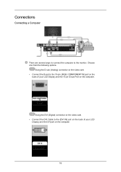
Using the DVI (Digital) connector on the video card. • Connect the DVI Cable to the [DVI IN] port on the back of your LCD Display and the DVI port on the computer. Using the D-sub (Analog) connector on the video card. • Connect the D-sub to the monitor. Choose one from the following options. Connections Connecting a Computer There are several ways to connect the computer to the 15-pin, [RGB / COMPONENT IN] port on the back of your LCD Display and the 15 pin D-sub Port on the computer. 18
Using the DVI (Digital) connector on the video card. • Connect the DVI Cable to the [DVI IN] port on the back of your LCD Display and the DVI port on the computer. Using the D-sub (Analog) connector on the video card. • Connect the D-sub to the monitor. Choose one from the following options. Connections Connecting a Computer There are several ways to connect the computer to the 15-pin, [RGB / COMPONENT IN] port on the back of your LCD Display and the 15 pin D-sub Port on the computer. 18
User Manual
Page 20
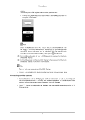
... DVI device so that follows. Note When the HDMI cable to the PC, ensure that you select HDMI from both your computer and the LCD Display. • Contact a local SAMSUNG Electronics Service Center to buy optional items. Connecting to Other devices • AV input devices such as DVD players, VCRs or camcorders as...
... DVI device so that follows. Note When the HDMI cable to the PC, ensure that you select HDMI from both your computer and the LCD Display. • Contact a local SAMSUNG Electronics Service Center to buy optional items. Connecting to Other devices • AV input devices such as DVD players, VCRs or camcorders as...
User Manual
Page 21
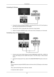
...the remote control. Connect the Component/ D-sub cable to the Video and Audio [R-AUDIO-L] LCD Display. 2. A component cable is optional. 20 Play the DVD, VCR or Camcorder with ...- Then, start the DVD Player with a DVD disc or tape inserted. 3. R] on the LCD Display and the AUDIO OUT jacks on the remote. Connecting AV Devices Connections 1. Connect the Video and Audio R-AUDIO-L port ...of the LCD display or on the DVD player or other external device. 2. Connecting using the SOURCE button on ...
...the remote control. Connect the Component/ D-sub cable to the Video and Audio [R-AUDIO-L] LCD Display. 2. A component cable is optional. 20 Play the DVD, VCR or Camcorder with ...- Then, start the DVD Player with a DVD disc or tape inserted. 3. R] on the LCD Display and the AUDIO OUT jacks on the remote. Connecting AV Devices Connections 1. Connect the Video and Audio R-AUDIO-L port ...of the LCD display or on the DVD player or other external device. 2. Connecting using the SOURCE button on ...
User Manual
Page 22
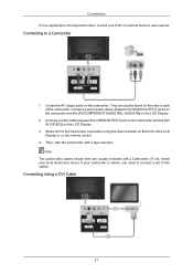
....) If your DVD or external device's user manual. Note The audio-video cables shown here are usually found on the side or back of the LCD Display or on the remote control. 4. Connections For an explanation of two cables. Connect a set of Component video, consult your camcorder is stereo, you need to... a Camcorder 1. Connecting to connect a set of audio cables between the VIDEO OUTPUT jack on the camcorder and the [AV IN [VIDEO]] on the LCD Display . 2. Connect a video cable between the AUDIO OUTPUT jacks on the camcorder and the [AV/COMPONENT AUDIO IN [L-AUDIO-R]] on the...
....) If your DVD or external device's user manual. Note The audio-video cables shown here are usually found on the side or back of the LCD Display or on the remote control. 4. Connections For an explanation of two cables. Connect a set of Component video, consult your camcorder is stereo, you need to... a Camcorder 1. Connecting to connect a set of audio cables between the VIDEO OUTPUT jack on the camcorder and the [AV IN [VIDEO]] on the LCD Display . 2. Connect a video cable between the AUDIO OUTPUT jacks on the camcorder and the [AV/COMPONENT AUDIO IN [L-AUDIO-R]] on the...
User Manual
Page 23
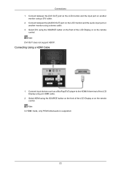
...input port on another monitor using a DVI cable. 2. Connect between the [AUDIO OUT] port on the LCD monitor and the audio input port on another monitor using the SOURCE button on the front of the LCD Display or on the remote control. Connect input devices such as a Blu-Ray/DVD player to the... HDMI IN terminal of the LCD Display using the SOURCE button on the front of the LCD Display or on the remote control. Select HDMI using a stereo cable. 3. Note DVI OUT does not support HDCP. Note In HDMI ...
...input port on another monitor using a DVI cable. 2. Connect between the [AUDIO OUT] port on the LCD monitor and the audio input port on another monitor using the SOURCE button on the front of the LCD Display or on the remote control. Connect input devices such as a Blu-Ray/DVD player to the... HDMI IN terminal of the LCD Display using the SOURCE button on the front of the LCD Display or on the remote control. Select HDMI using a stereo cable. 3. Note DVI OUT does not support HDCP. Note In HDMI ...
User Manual
Page 24
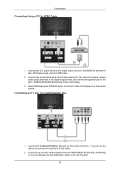
... HDMI cable. 2. Connect the DVI output terminal of a digital output device to the [HDMI IN] terminal of the LCD Display or on the Set Top Box 23 Connecting a DTV Set Top (Cable/Satellite) Box 1. Connect the [RGB/COMPONENT...] terminal of audio cables between the [AV/COMPONENT AUDIO IN [L-AUDIO-R]] on the LCD Display and the AUDIO OUT jacks on the remote control. Select HDMI using the SOURCE button on the set of the... LCD Display. 3. Connect the red and white jacks of an RCA to stereo (for PC) cable ...
... HDMI cable. 2. Connect the DVI output terminal of a digital output device to the [HDMI IN] terminal of the LCD Display or on the Set Top Box 23 Connecting a DTV Set Top (Cable/Satellite) Box 1. Connect the [RGB/COMPONENT...] terminal of audio cables between the [AV/COMPONENT AUDIO IN [L-AUDIO-R]] on the LCD Display and the AUDIO OUT jacks on the remote control. Select HDMI using the SOURCE button on the set of the... LCD Display. 3. Connect the red and white jacks of an RCA to stereo (for PC) cable ...
User Manual
Page 25
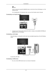
Connecting to an Audio System 1. Connect a set of the LCD Display or on the remote control. Connections Note Select Component using the SOURCE button on the front of audio cables between the AUX L, R jacks on the AUDIO SYSTEM and [AUDIO OUT] on LCD Display. Connecting a LAN Cable The LCD Display 's configuration at the back may vary slightly depending on the LCD Display model. Connecting a USB device • You can connect USB devices such as a mouse or keyboard. 24 For an explanation of Component video, see your Set Top Box owner's manual. Connect the LAN cable.
Connecting to an Audio System 1. Connect a set of the LCD Display or on the remote control. Connections Note Select Component using the SOURCE button on the front of audio cables between the AUX L, R jacks on the AUDIO SYSTEM and [AUDIO OUT] on LCD Display. Connecting a LAN Cable The LCD Display 's configuration at the back may vary slightly depending on the LCD Display model. Connecting a USB device • You can connect USB devices such as a mouse or keyboard. 24 For an explanation of Component video, see your Set Top Box owner's manual. Connect the LAN cable.
User Manual
Page 39
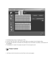
If the exact port name that is not selected, communication will be selected in the program and used , COM1 through COM4 can be unavailable. 4. Power Control 1. The Multiple Display Control is originally set to the LCD Display using a serial cable is connected to COM1. 2. Click Power Control of the main icons and the Power Control screen appears. 1. If any port other than COM1 is stored in the Port Selection Menu. 3. The selected port is used for the next program as well.
If the exact port name that is not selected, communication will be selected in the program and used , COM1 through COM4 can be unavailable. 4. Power Control 1. The Multiple Display Control is originally set to the LCD Display using a serial cable is connected to COM1. 2. Click Power Control of the main icons and the Power Control screen appears. 1. If any port other than COM1 is stored in the Port Selection Menu. 3. The selected port is used for the next program as well.
User Manual
Page 47
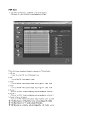
... changes the size to Large. 4) Small - Shows the current PIP Size of the selected display and changes the size to PIP Size Control. 1) PIP Size - Turns on the PIP of the display in use Check Box to select a display to Double 2. 7) Double 3 (Picture By Picture) - PIP Size can be controlled with ... control. The Input source of the selected display and changes the size to Double 3. Turns off the PIP of the main icons and the PIP control screen appears. The Input source of TV works only on the PBP of MagicInfo works only on the LCD Display power. Click Select All or use . ...
... changes the size to Large. 4) Small - Shows the current PIP Size of the selected display and changes the size to PIP Size Control. 1) PIP Size - Turns on the PIP of the display in use Check Box to select a display to Double 2. 7) Double 3 (Picture By Picture) - PIP Size can be controlled with ... control. The Input source of the selected display and changes the size to Double 3. Turns off the PIP of the main icons and the PIP control screen appears. The Input source of TV works only on the PBP of MagicInfo works only on the LCD Display power. Click Select All or use . ...
User Manual
Page 48
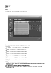
...feature is available only for selection, depending on the input source type of the Main Screen. Changes the source of the PIP of the selected display to Component. 8) HDMI - The Input source of the PIP Sources may not be controlled with turning on MagicInfo model. Note: Some of ...MagicInfo works only on the LCD Display power. 2) PC - Info Grid shows some basic information necessary to ON. Changes the source of the PIP of the selected display to AV. 6) S-Video - Changes the source of the PIP of the main icons...
...feature is available only for selection, depending on the input source type of the Main Screen. Changes the source of the PIP of the selected display to Component. 8) HDMI - The Input source of the PIP Sources may not be controlled with turning on MagicInfo model. Note: Some of ...MagicInfo works only on the LCD Display power. 2) PC - Info Grid shows some basic information necessary to ON. Changes the source of the PIP of the selected display to AV. 6) S-Video - Changes the source of the PIP of the main icons...
User Manual
Page 56
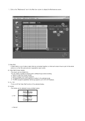
... - Turns on the "Maintenance" icon in the selected mode. z Full z Natural A Video Wall is a set up to 5x5 LCD Displayes. 3) On / Off - z The place will be set of video screens that are connected together, so that each screen shows a part of the whole picture ...so that the same picture is repeated on each screen. 2) Video Wall (Screen divider) - z The MDC program supplied by Samsung supports up by pressing a number in the Main Icon column to see a divided screen. 1. z Select a mode from Display Selection. The screen can be divided into. The format can be selected to...
... - Turns on the "Maintenance" icon in the selected mode. z Full z Natural A Video Wall is a set up to 5x5 LCD Displayes. 3) On / Off - z The place will be set of video screens that are connected together, so that each screen shows a part of the whole picture ...so that the same picture is repeated on each screen. 2) Video Wall (Screen divider) - z The MDC program supplied by Samsung supports up by pressing a number in the Main Icon column to see a divided screen. 1. z Select a mode from Display Selection. The screen can be divided into. The format can be selected to...


