Quick Start Guide
Page 25
... sources are turned on. Q: The picture image is off. A: Adjust the Brightness and Contrast. (Refer to the current Information under the LCD Display menu and Preset Timing Modes. Q: Ghost images are listed. A: Run Frequency Coarse and Fine tuning. If not, reset them referring to ... cable is too light or too dark. Troubleshooting A: Check if the signal cable between the computer and the LCD Display is blurred. A: Compare these values with the data in the picture. picture is securely connected. (Refer to Connecting a Computer) Problems related to the Screen Note...
... sources are turned on. Q: The picture image is off. A: Adjust the Brightness and Contrast. (Refer to the current Information under the LCD Display menu and Preset Timing Modes. Q: Ghost images are listed. A: Run Frequency Coarse and Fine tuning. If not, reset them referring to ... cable is too light or too dark. Troubleshooting A: Check if the signal cable between the computer and the LCD Display is blurred. A: Compare these values with the data in the picture. picture is securely connected. (Refer to Connecting a Computer) Problems related to the Screen Note...

User Manual
Page 30
Introduction Make sure to use the top center, and not the left or the right side of the product to Send 9 Ring Indicator Remote Control (RS232C) Cable connections interface pin Bits rate Data Bits Parity Stop Bits Flow control Maximum length RS232C(9 pin) TxD(No.2) RxD(No.3) GND(No.5) 9600 bps 8 bit None 1 bit None 15 m (only shielded type) • Pin assignment Pin Signal 1 Data Carrier Detect 2 Received Data 3 Transmitted Data 4 Data Terminal Ready 5 Signal Ground 6 Data Set Ready 7 Request to Send 8 Clear to adjust the angle.
Introduction Make sure to use the top center, and not the left or the right side of the product to Send 9 Ring Indicator Remote Control (RS232C) Cable connections interface pin Bits rate Data Bits Parity Stop Bits Flow control Maximum length RS232C(9 pin) TxD(No.2) RxD(No.3) GND(No.5) 9600 bps 8 bit None 1 bit None 15 m (only shielded type) • Pin assignment Pin Signal 1 Data Carrier Detect 2 Received Data 3 Transmitted Data 4 Data Terminal Ready 5 Signal Ground 6 Data Set Ready 7 Request to Send 8 Clear to adjust the angle.

User Manual
Page 31
Introduction • RS232C cable Connector : 9-pin D-Sub Cable : Cross (reversed) cable -P1- -P1- command type DATA Length ID CheckSum 0 DATA Length 1 DATA Value CheckSum command Value range FEMALE Rx 2 Tx 3 Gnd 5 • Connecting method -P2- -P2- 3 Rx FEMALE 2 Tx 5 Gnd Control codes • Get control Header 0xAA command command type • Set control Header command ID 0xAA command type • commanding words No.
Introduction • RS232C cable Connector : 9-pin D-Sub Cable : Cross (reversed) cable -P1- -P1- command type DATA Length ID CheckSum 0 DATA Length 1 DATA Value CheckSum command Value range FEMALE Rx 2 Tx 3 Gnd 5 • Connecting method -P2- -P2- 3 Rx FEMALE 2 Tx 5 Gnd Control codes • Get control Header 0xAA command command type • Set control Header command ID 0xAA command type • commanding words No.

User Manual
Page 32
... 0 8 Video wall Mode control 0x5C 0~1 9 Safety Lock 0x5D 0~1 - example)PowerOn&ID=0 Header command ID 0xAA 0x11 DATA Length 1 DATA 1 Power CheckSum Header command ID 0xAA 0x11 DATA DATA 1 Length 12 1 1 If you want to control every mechanism connected with ACK. • Power Control • Function ... Monitor power ON/OFF. • Get Power ON/OFF Status Header 0xAA command 0x11 ID DATA Length CheckSum 0 • Set Power ON/OFF Header command ID 0xAA 0x11 DATA Length 1 Power : Power code to "0xFE" and send commands. Every communication will not ...
... 0 8 Video wall Mode control 0x5C 0~1 9 Safety Lock 0x5D 0~1 - example)PowerOn&ID=0 Header command ID 0xAA 0x11 DATA Length 1 DATA 1 Power CheckSum Header command ID 0xAA 0x11 DATA DATA 1 Length 12 1 1 If you want to control every mechanism connected with ACK. • Power Control • Function ... Monitor power ON/OFF. • Get Power ON/OFF Status Header 0xAA command 0x11 ID DATA Length CheckSum 0 • Set Power ON/OFF Header command ID 0xAA 0x11 DATA Length 1 Power : Power code to "0xFE" and send commands. Every communication will not ...

User Manual
Page 33
...8226; Function Personal Computer changes volume of TV / Monitor. • Get Volume Status Header 0xAA command 0x12 DATA Length ID CheckSum 0 • Set Volume Header command ID 0xAA 0x12 DATA Length 1 DATA Volume Volume : Volume value code to be set on TV / Monitor (0 ~ 100) CheckSum •... Ack Header command ID 0xAA 0xFF Volume : Same as above DATA Length 3 Ack/Nak 'A' r-CMD 0x12 Val1 Volume Check Sum • Nak Header 0xAA command 0xFF ID DATA Length Ack/Nak r-CMD 3 'N' 0x12 ERR : Error code that shows what occurred error is...
...8226; Function Personal Computer changes volume of TV / Monitor. • Get Volume Status Header 0xAA command 0x12 DATA Length ID CheckSum 0 • Set Volume Header command ID 0xAA 0x12 DATA Length 1 DATA Volume Volume : Volume value code to be set on TV / Monitor (0 ~ 100) CheckSum •... Ack Header command ID 0xAA 0xFF Volume : Same as above DATA Length 3 Ack/Nak 'A' r-CMD 0x12 Val1 Volume Check Sum • Nak Header 0xAA command 0xFF ID DATA Length Ack/Nak r-CMD 3 'N' 0x12 ERR : Error code that shows what occurred error is...

User Manual
Page 34
...; Function Personal Computer changes input source of TV / Monitor. • Get Input Source Status Header 0xAA command 0x14 DATA Length ID CheckSum 0 • Set Input Source Header command ID 0xAA 0x14 DATA Length 1 DATA CheckSum Input Source Input Source : Input Source code to be set on TV / Monitor 0x14 0x1E 0x18 0x0C 0x04... case of MagicInfo, only possible with models include MagicInfo In the case of TV, only possible with models include TV. • Ack Header command ID DATA Length Ack/Nak r-CMD Val1 Check Sum
...; Function Personal Computer changes input source of TV / Monitor. • Get Input Source Status Header 0xAA command 0x14 DATA Length ID CheckSum 0 • Set Input Source Header command ID 0xAA 0x14 DATA Length 1 DATA CheckSum Input Source Input Source : Input Source code to be set on TV / Monitor 0x14 0x1E 0x18 0x0C 0x04... case of MagicInfo, only possible with models include MagicInfo In the case of TV, only possible with models include TV. • Ack Header command ID DATA Length Ack/Nak r-CMD Val1 Check Sum

User Manual
Page 35
Caution Only works with models include TV. • Get Screen Mode Status Header 0xAA command 0x18 DATA Length ID CheckSum 0 • Set Picture Size Header command ID 0xAA 0x18 DATA Length 1 DATA Screen Mode Screen Mode : Screen Mode code to be controlled when Video Wall is Val1 ERR Check... Mode" of TV/Monitor. Introduction 0xAA 0xFF 3 Input Source : Same as above 'A' 0x14 Input Source • Nak Header 0xAA command 0xFF ID DATA Length Ack/Nak r-CMD 3 'N' 0x14 ERR : Error code that shows what occurred error is on. Cannot be set on TV / Monitor 0x01 ...
Caution Only works with models include TV. • Get Screen Mode Status Header 0xAA command 0x18 DATA Length ID CheckSum 0 • Set Picture Size Header command ID 0xAA 0x18 DATA Length 1 DATA Screen Mode Screen Mode : Screen Mode code to be controlled when Video Wall is Val1 ERR Check... Mode" of TV/Monitor. Introduction 0xAA 0xFF 3 Input Source : Same as above 'A' 0x14 Input Source • Nak Header 0xAA command 0xFF ID DATA Length Ack/Nak r-CMD 3 'N' 0x14 ERR : Error code that shows what occurred error is on. Cannot be set on TV / Monitor 0x01 ...

User Manual
Page 36
...Function Personal Computer recognizes the screen size of TV / Monitor. • Get Screen Size Status Header 0xAA command 0x19 DATA Length ID CheckSum 0 • Ack Header 0xAA command 0xFF ID DATA Length Ack/Nak r-CMD 3 'A' 0x19 Val1 Screen Size Check Sum Screen Size : Screen Size of TV / Monitor... (Range : 0 ~ 255, Unit : Inch) • Nak Header 0xAA command 0xFF ID DATA Length Ack/Nak r-CMD 3 'N' 0x19 ERR : Error code that shows what occurred error is Val1 ERR Check Sum • PIP ON / OFF Control ...
...Function Personal Computer recognizes the screen size of TV / Monitor. • Get Screen Size Status Header 0xAA command 0x19 DATA Length ID CheckSum 0 • Ack Header 0xAA command 0xFF ID DATA Length Ack/Nak r-CMD 3 'A' 0x19 Val1 Screen Size Check Sum Screen Size : Screen Size of TV / Monitor... (Range : 0 ~ 255, Unit : Inch) • Nak Header 0xAA command 0xFF ID DATA Length Ack/Nak r-CMD 3 'N' 0x19 ERR : Error code that shows what occurred error is Val1 ERR Check Sum • PIP ON / OFF Control ...

User Manual
Page 37
...the PIP ON / OFF Header command ID 0xAA 0x3C DATA Length 1 DATA PIP PIP : The PIP ON / OFF code to set for the TV or Monitor 1 : PIP ON 0 : PIP OFF CheckSum • Ack Header command ID 0xAA 0xFF PIP : Same as above DATA Length 3 Ack/Nak 'A' r-CMD 0x3C Val1 PIP Check... Sum • Nak Header 0xAA command 0xFF ID DATA Length Ack/Nak r-CMD 3 'N' 0x3C ERR : Error code that shows what occurred error is Val1 ERR Check...
...the PIP ON / OFF Header command ID 0xAA 0x3C DATA Length 1 DATA PIP PIP : The PIP ON / OFF code to set for the TV or Monitor 1 : PIP ON 0 : PIP OFF CheckSum • Ack Header command ID 0xAA 0xFF PIP : Same as above DATA Length 3 Ack/Nak 'A' r-CMD 0x3C Val1 PIP Check... Sum • Nak Header 0xAA command 0xFF ID DATA Length Ack/Nak r-CMD 3 'N' 0x3C ERR : Error code that shows what occurred error is Val1 ERR Check...

User Manual
Page 38
... is ON. Does not operate in MagicInfo • Get Video Wall Mode Header 0xAA command 0x5C DATA Length ID CheckSum 0 • Set Video Wall Mode Header command ID 0xAA 0x5C DATA Length 1 DATA CheckSum Video Wall Mode Video Wall Mode : Video Wall Mode code to be set on . Introduction... 0xAA 0xFF 3 'A' 0x3D Auto Adjustment • Nak Header 0xAA command 0xFF ID DATA Length Ack/Nak r-CMD 3 'N' 0x3D ERR : Error code that shows what occurred error is Val1 ERR Check Sum • Video Wall Mode Control &#...
... is ON. Does not operate in MagicInfo • Get Video Wall Mode Header 0xAA command 0x5C DATA Length ID CheckSum 0 • Set Video Wall Mode Header command ID 0xAA 0x5C DATA Length 1 DATA CheckSum Video Wall Mode Video Wall Mode : Video Wall Mode code to be set on . Introduction... 0xAA 0xFF 3 'A' 0x3D Auto Adjustment • Nak Header 0xAA command 0xFF ID DATA Length Ack/Nak r-CMD 3 'N' 0x3D ERR : Error code that shows what occurred error is Val1 ERR Check Sum • Video Wall Mode Control &#...

User Manual
Page 39
...CheckSum 0 • Set Safety Lock Enable / Disable Header command ID 0xAA 0x5D DATA Length 1 Safety Lock : Lock code to be set on TV / Monitor 1 : ON 0 : OFF DATA CheckSum Safety Lock • Ack Header 0xAA command 0xFF ID DATA Length Ack/Nak r-CMD 3 'A' 0x5D Val1 Safety Lock Check Sum Safety Lock ...: Same as above • Nak Header 0xAA command 0xFF ID DATA Length Ack/Nak r-CMD 3 'N' 0x5D Val1 Safety Lock Check Sum ERR : Error code that shows what occurred error is Val1 ERR Check ...
...CheckSum 0 • Set Safety Lock Enable / Disable Header command ID 0xAA 0x5D DATA Length 1 Safety Lock : Lock code to be set on TV / Monitor 1 : ON 0 : OFF DATA CheckSum Safety Lock • Ack Header 0xAA command 0xFF ID DATA Length Ack/Nak r-CMD 3 'A' 0x5D Val1 Safety Lock Check Sum Safety Lock ...: Same as above • Nak Header 0xAA command 0xFF ID DATA Length Ack/Nak r-CMD 3 'N' 0x5D Val1 Safety Lock Check Sum ERR : Error code that shows what occurred error is Val1 ERR Check ...

User Manual
Page 59
Multiple display control "MDC" is MDC? Connecting to MDC Using MDC via RS-232C (serial data communications standards) An RS-232C serial cable must be connected to easily control multiple display devices simultaneously using a PC. What is an application that allows you to the serial ports on the PC and monitor.
Multiple display control "MDC" is MDC? Connecting to MDC Using MDC via RS-232C (serial data communications standards) An RS-232C serial cable must be connected to easily control multiple display devices simultaneously using a PC. What is an application that allows you to the serial ports on the PC and monitor.

User Manual
Page 88
Check that another even though On Time or Off Time is within the range of 0 to 99, the ID should be shown due to data collision. 3. The remote control does not work if the RS-232C cable is removed or the program is closed abnormally while the Remote Control function ... powered on. (See the power status in a range of 0 and 99. (Change the ID using the Display menu.) For a display that the cable is connected to. To resolve this, run the program again and set . Displays power on or off at different time from nearby electronic devices. Check the connection of the RS232C...
Check that another even though On Time or Off Time is within the range of 0 to 99, the ID should be shown due to data collision. 3. The remote control does not work if the RS-232C cable is removed or the program is closed abnormally while the Remote Control function ... powered on. (See the power status in a range of 0 and 99. (Change the ID using the Display menu.) For a display that the cable is connected to. To resolve this, run the program again and set . Displays power on or off at different time from nearby electronic devices. Check the connection of the RS232C...

User Manual
Page 134
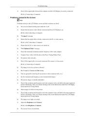
... on again after removing all accessories (video extension cable, etc.) A: Set the resolution and frequency to the current Information under the LCD Display menu and Preset Timing Modes. A: Check the maximum resolution and the frequency of the video Adaptor. A: Turn on . Troubleshooting A:... Computer) Problems related to the Screen Note Problems related to the Brightness, Contrast) A: Compare these values with the data in the range supported by the LCD Display. A: Check if the resolution and frequency set for the computer video card falls in the Preset Timing Modes Chart. ...
... on again after removing all accessories (video extension cable, etc.) A: Set the resolution and frequency to the current Information under the LCD Display menu and Preset Timing Modes. A: Check the maximum resolution and the frequency of the video Adaptor. A: Turn on . Troubleshooting A:... Computer) Problems related to the Screen Note Problems related to the Brightness, Contrast) A: Compare these values with the data in the range supported by the LCD Display. A: Check if the resolution and frequency set for the computer video card falls in the Preset Timing Modes Chart. ...


