Quick Guide (ENGLISH)
Page 12
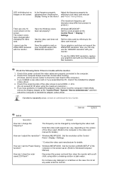
...Display→Settings. * Contact the video card manufacturer for details.) How can I clean the outer case/LCD Panel? Has the video card been set at the Control Panel → Display → Settings. I...your graphics card does not support the 2560x1600 resolution, then you can I adjust the resolution? If your monitor. Check if the computer beeps more than 3 times when booting. (If it does, ask the service...video card. Check if the scanning ratio of the driver used. (Refer to check the main board of the function? Windows ME/XP/2000 : Set the resolution at the "Control Panel→...
...Display→Settings. * Contact the video card manufacturer for details.) How can I clean the outer case/LCD Panel? Has the video card been set at the Control Panel → Display → Settings. I...your graphics card does not support the 2560x1600 resolution, then you can I adjust the resolution? If your monitor. Check if the computer beeps more than 3 times when booting. (If it does, ask the service...video card. Check if the scanning ratio of the driver used. (Refer to check the main board of the function? Windows ME/XP/2000 : Set the resolution at the "Control Panel→...

User Manual (ENGLISH)
Page 19
...times when booting. (If it does, ask the service center to check the main board of the video screen is trouble with your computer support the 2560x1600 resolution? Has the ... cloth, using the maximum resolution.) 5. Disconnect the power cord and then clean the monitor with the monitor. (The maximum frequency per resolution may differ from product to the computer or the video... Hz when using either a cleaning solution or plain water. How can I clean the outer case/LCD Panel? The screen colors have problems in installing the adapter (video) driver, boot the computer in...
...times when booting. (If it does, ask the service center to check the main board of the video screen is trouble with your computer support the 2560x1600 resolution? Has the ... cloth, using the maximum resolution.) 5. Disconnect the power cord and then clean the monitor with the monitor. (The maximum frequency per resolution may differ from product to the computer or the video... Hz when using either a cleaning solution or plain water. How can I clean the outer case/LCD Panel? The screen colors have problems in installing the adapter (video) driver, boot the computer in...

Service Manual
Page 3
... Cable) 3-1 Receive/Download the proper DDC file for adjusting the monitor: Computer with Windows 95, Windows 98, or Windows NT. 3 Alignments and Adjustments 3 Alignments and Adjustments This section of the service manual explains how to use ... (25P Cable) 3-3 Hidden Key list MTI-2055 DDC Manager Figure 1. Install the below jig (Figure 1) and enter the data. This function is needed for AD board change and program memory (IC200) change. 3-1 Required Equipment The following equipment is necessary for the model from HQ quality control department. MTI-2055 DDC MANAGER...
... Cable) 3-1 Receive/Download the proper DDC file for adjusting the monitor: Computer with Windows 95, Windows 98, or Windows NT. 3 Alignments and Adjustments 3 Alignments and Adjustments This section of the service manual explains how to use ... (25P Cable) 3-3 Hidden Key list MTI-2055 DDC Manager Figure 1. Install the below jig (Figure 1) and enter the data. This function is needed for AD board change and program memory (IC200) change. 3-1 Required Equipment The following equipment is necessary for the model from HQ quality control department. MTI-2055 DDC MANAGER...

Service Manual
Page 4
Click "WRITE EEPROM"± Confirm the "OK" Sign Error Massage: Check the Signal Cable or Interface Board 3-2 3 Alignments and Adjustments 3-4 EDID Installation with Dos Program 1.Execute "DDC21.exe"± 2.Click "LOAD FILE"± 3.File Name "305T.DDC" 4.
Click "WRITE EEPROM"± Confirm the "OK" Sign Error Massage: Check the Signal Cable or Interface Board 3-2 3 Alignments and Adjustments 3-4 EDID Installation with Dos Program 1.Execute "DDC21.exe"± 2.Click "LOAD FILE"± 3.File Name "305T.DDC" 4.

Service Manual
Page 5
Click "Open" icon. 3 Alignments and Adjustments 3-5 EDID Installation with Windows Program 1. Click "Sys Config"± Select "Station : Write station". Check "Serial No and Week : Don't change"± Click "Save"± 3. With 1 beep sound, Factory Reset executes. 3-3 After Replacing the Main Board -EDID Installation (Analog and Digital) -Factory Reset(Using Power key) During Power off, press Power key for 5 seconds. Select "Connected Port #1" and Next "OK". * File Name - 305T.DDC Press enter key on your keyboard. 4. Confirm the "DDC OK". - Execute "WinDDC.exe" 2.
Click "Open" icon. 3 Alignments and Adjustments 3-5 EDID Installation with Windows Program 1. Click "Sys Config"± Select "Station : Write station". Check "Serial No and Week : Don't change"± Click "Save"± 3. With 1 beep sound, Factory Reset executes. 3-3 After Replacing the Main Board -EDID Installation (Analog and Digital) -Factory Reset(Using Power key) During Power off, press Power key for 5 seconds. Select "Connected Port #1" and Next "OK". * File Name - 305T.DDC Press enter key on your keyboard. 4. Confirm the "DDC OK". - Execute "WinDDC.exe" 2.

Service Manual
Page 14
11 Disassembly and Reassembly Description 3. Remove 1screws from the Shield between LCD_psanel and Shield 6. Disconnect cables and remove the inverter power and function cable Picture Description 4. Remove 4screws from the Shield. 5. Disconnect cables LVDS and Signal from Panel control board 11-2
11 Disassembly and Reassembly Description 3. Remove 1screws from the Shield between LCD_psanel and Shield 6. Disconnect cables and remove the inverter power and function cable Picture Description 4. Remove 4screws from the Shield. 5. Disconnect cables LVDS and Signal from Panel control board 11-2

Service Manual
Page 15
Description 7. Remove 2 screw on the main board 10.Remove 3 screws on the SMPS board 11-3 Remove 2screws from DVI input connector 11 Disassembly and Reassembly Picture Description 8. Up and down the chassis ass'y 9.
Description 7. Remove 2 screw on the main board 10.Remove 3 screws on the SMPS board 11-3 Remove 2screws from DVI input connector 11 Disassembly and Reassembly Picture Description 8. Up and down the chassis ass'y 9.

Service Manual
Page 16
11 Disassembly and Reassembly Description 11.Disconnect cables LVDS and Signal and Power from Main board Picture Description 11-3 Reassembly Reassembly procedures are in the reverse order of disassembly procedures. 11-4
11 Disassembly and Reassembly Description 11.Disconnect cables LVDS and Signal and Power from Main board Picture Description 11-3 Reassembly Reassembly procedures are in the reverse order of disassembly procedures. 11-4

Service Manual
Page 17
...30,LCD-MO,CHINA 0.1 M0001 BN90-01014G ..2 T0003 BN96-03652F ...3 M0112 BN63-02663D ...3 T0022 BN64-00504A ...3 T0054 BN64-00505A ...3 M0145 BN96-04050A ..2 T0382 BP61-00495C ASSY COVER FRONT;LS30HUX_305T PLUS ASSY COVER P-FRONT;LS30HUX(305T PLUS),,H COVER-FRONT;LS30HUX (305T...,HIPS HB,2.5 COVER-STAND LIFT FRONT;HUBBLE,HIPS HB,2. URL : http://itself.sec.samsung.co.kr/ 6-1. LS30HUXCB/XSF Parts List Level Loc. COVER-STAND LIFT REAR;HUBBLE...* CONNECTOR-DVI;24P,3R,FEMALE,ANGLE,AUF HEADER-BOARD TO CABLE;BOX,3P,1R,2.5MM,AN HEADER-BOARD TO CABLE;BOX,16P,1R,2mm,ANG JACK-USB...
...30,LCD-MO,CHINA 0.1 M0001 BN90-01014G ..2 T0003 BN96-03652F ...3 M0112 BN63-02663D ...3 T0022 BN64-00504A ...3 T0054 BN64-00505A ...3 M0145 BN96-04050A ..2 T0382 BP61-00495C ASSY COVER FRONT;LS30HUX_305T PLUS ASSY COVER P-FRONT;LS30HUX(305T PLUS),,H COVER-FRONT;LS30HUX (305T...,HIPS HB,2.5 COVER-STAND LIFT FRONT;HUBBLE,HIPS HB,2. URL : http://itself.sec.samsung.co.kr/ 6-1. LS30HUXCB/XSF Parts List Level Loc. COVER-STAND LIFT REAR;HUBBLE...* CONNECTOR-DVI;24P,3R,FEMALE,ANGLE,AUF HEADER-BOARD TO CABLE;BOX,3P,1R,2.5MM,AN HEADER-BOARD TO CABLE;BOX,16P,1R,2mm,ANG JACK-USB...

Service Manual
Page 23
...-RESET;DS1834A,SOIC,8P,150MIL,PLASTIC, DIODE-TVS;NUP4301MR6,6/-/-V,500W,TSOP-6 DIODE-TVS;NUP4301MR6,6/-/-V,500W,TSOP-6 HEADER-BOARD TO CABLE;BOX,30P,1R,1.25mm, HEADER-BOARD TO CABLE;BOX,15P,1R,1.25MM, HEADER-BOARD TO CABLE;BOX,6P,1R,1.25mm,S R-CHIP;2.4Kohm,5%,1/10W,TP,1608 FET-SILICON;Si4435BDY-T1-E3,P,-30V,-9.1A... FET-SILICON;Si4435BDY-T1-E3,P,-30V,-9.1A HEADER-BOARD TO BOARD;BOX,14P,1R,2mm,ANG SOLDER-WIRE FLUX;LFC7-107,D0.8,99.3Sn/0. Level Loc. No. ASSY SHIELD P-COVER;HUBBLE,SECC,T0.8 SHIELD-...
...-RESET;DS1834A,SOIC,8P,150MIL,PLASTIC, DIODE-TVS;NUP4301MR6,6/-/-V,500W,TSOP-6 DIODE-TVS;NUP4301MR6,6/-/-V,500W,TSOP-6 HEADER-BOARD TO CABLE;BOX,30P,1R,1.25mm, HEADER-BOARD TO CABLE;BOX,15P,1R,1.25MM, HEADER-BOARD TO CABLE;BOX,6P,1R,1.25mm,S R-CHIP;2.4Kohm,5%,1/10W,TP,1608 FET-SILICON;Si4435BDY-T1-E3,P,-30V,-9.1A... FET-SILICON;Si4435BDY-T1-E3,P,-30V,-9.1A HEADER-BOARD TO BOARD;BOX,14P,1R,2mm,ANG SOLDER-WIRE FLUX;LFC7-107,D0.8,99.3Sn/0. Level Loc. No. ASSY SHIELD P-COVER;HUBBLE,SECC,T0.8 SHIELD-...

Service Manual
Page 26
...-03652F BN07-00470A BN96-04050A BN94-01009S BN96-03656A BN61-02582A BN90-01015A BN96-04718B Item & Specification ASSY COVER P-FRONT;LS30HUX(305T PLUS),,H LCD-PANEL;LTM300M1-P02,Hubble,8BIT,677.3 ASSY BOARD P-FUNCTION;HUBBLE,SJ06-01-013 ASSY PCB MAIN-SPZ,W/W;LS30HUB* ASSY SHIELD P-COVER;HUBBLE,SECC,T0.8 BRACKET-SUPPORT;HUBBLE,SPTE,0.3 ASSY...
...-03652F BN07-00470A BN96-04050A BN94-01009S BN96-03656A BN61-02582A BN90-01015A BN96-04718B Item & Specification ASSY COVER P-FRONT;LS30HUX(305T PLUS),,H LCD-PANEL;LTM300M1-P02,Hubble,8BIT,677.3 ASSY BOARD P-FUNCTION;HUBBLE,SJ06-01-013 ASSY PCB MAIN-SPZ,W/W;LS30HUB* ASSY SHIELD P-COVER;HUBBLE,SECC,T0.8 BRACKET-SUPPORT;HUBBLE,SPTE,0.3 ASSY...
Service Manual
Page 31
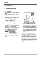
Inspect each lead dress to modify the circuit board. 2. Leakage Current Hot Check (Figure 1-1): WARNING : Do not use an isolation transformer during this meter periodically. 1-1-3 Fire and Shock Hazard Before returning the monitor to protect against potential hazards such as nonmetallic control ... by replacing them with American National Standards Institute (ANSI C101.1, Leakage Current for higher voltage, wattage, etc. When servicing the LCD Monitor, Disconnect the AC line cord from visual inspection. Use a leakage current tester or a metering system that hardware is not lodged...
Inspect each lead dress to modify the circuit board. 2. Leakage Current Hot Check (Figure 1-1): WARNING : Do not use an isolation transformer during this meter periodically. 1-1-3 Fire and Shock Hazard Before returning the monitor to protect against potential hazards such as nonmetallic control ... by replacing them with American National Standards Institute (ANSI C101.1, Leakage Current for higher voltage, wattage, etc. When servicing the LCD Monitor, Disconnect the AC line cord from visual inspection. Use a leakage current tester or a metering system that hardware is not lodged...

Service Manual
Page 32
Always unplug the unit's AC power cord from the leads of a replacement ESD, touch the protective material to the monitor. 2. Some components are electrically shorted together by static electricity. Check the insulation between the following techniques will be greater than 1 megohm. 6....an insulation resistance meter (500 V) to damage an ESD. 1-2 Examples of the AC plug and accessible conductive parts (see above the printed circuit board for safety. An insulation tube or tape is applied to the chassis or circuit and observe all such elements to : (a) remove or reinstall any...
Always unplug the unit's AC power cord from the leads of a replacement ESD, touch the protective material to the monitor. 2. Some components are electrically shorted together by static electricity. Check the insulation between the following techniques will be greater than 1 megohm. 6....an insulation resistance meter (500 V) to damage an ESD. 1-2 Examples of the AC plug and accessible conductive parts (see above the printed circuit board for safety. An insulation tube or tape is applied to the chassis or circuit and observe all such elements to : (a) remove or reinstall any...
Service Manual
Page 47
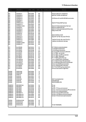
...Panel code derivation for AMLCD 32" 16:9 NEW Panel AMLCD 46" 16:9 SPVA 72% NEW Panel All LCD Monitor 24" wide SPVA ZPD NEW code derivation AMLCD 19" TN Glare NEW Panel Code AMLCD 19" TN ...Wide change Gamma Panel Code AMLCD 19" TN NEW Panel Code AMLCD 19" TN Wide High brightness NEW Panel Code Display-LCD (Div) 07AH AMLCD LTM170EX-L31 ZPD AMLCD 46" 16:9 FHD / 60Hz / 8bit / SPVA 92% AMLCD 46" 16...00270A NTZ BN07-00317A NTZ BN07-00021A RA BN07-00042A RB BN07-00048A RC BN07-00059A RD IP Board for Digital Album TSB 15" high brightness Panel Toshiba ZPD panel TSB LTM15C458S ( ZPD ) TTL ...
...Panel code derivation for AMLCD 32" 16:9 NEW Panel AMLCD 46" 16:9 SPVA 72% NEW Panel All LCD Monitor 24" wide SPVA ZPD NEW code derivation AMLCD 19" TN Glare NEW Panel Code AMLCD 19" TN ...Wide change Gamma Panel Code AMLCD 19" TN NEW Panel Code AMLCD 19" TN Wide High brightness NEW Panel Code Display-LCD (Div) 07AH AMLCD LTM170EX-L31 ZPD AMLCD 46" 16:9 FHD / 60Hz / 8bit / SPVA 92% AMLCD 46" 16...00270A NTZ BN07-00317A NTZ BN07-00021A RA BN07-00042A RB BN07-00048A RC BN07-00059A RD IP Board for Digital Album TSB 15" high brightness Panel Toshiba ZPD panel TSB LTM15C458S ( ZPD ) TTL ...

Service Manual
Page 53
... pin 9-12 of CN401 No Check IC401 and related circuit Yes Dose proper +24V_IN at Pin 3 of the SMPS and related circuit Yes Check LCD Panel and replace LCD Panel 4-3 Yes When Pin 1 of IC601 is DC 6V does proper DC 3.3V appear at pin 14-16 of CN600 No Check +24... output of IC601? Yes Dose proper DC3.3V appear at SMPS board and related circuit No Check IC601 and related circuit. Yes X-200 oscillate Properly? (Where...
... pin 9-12 of CN401 No Check IC401 and related circuit Yes Dose proper +24V_IN at Pin 3 of the SMPS and related circuit Yes Check LCD Panel and replace LCD Panel 4-3 Yes When Pin 1 of IC601 is DC 6V does proper DC 3.3V appear at pin 14-16 of CN600 No Check +24... output of IC601? Yes Dose proper DC3.3V appear at SMPS board and related circuit No Check IC601 and related circuit. Yes X-200 oscillate Properly? (Where...


