
English Manual
Page 2
... distributed under license from Reebok International. 2 REEBOK and the Vector Logo are registered trademarks and service marks of this manual and request a free replacement decal. TABLE OF CONTENTS WARNING DECAL PLACEMENT 2 IMPORTANT PRECAUTIONS 3 BEFORE YOU BEGIN 4 ASSEMBLY 5 HOW TO USE THE ELLIPTICAL 14 FCC INFORMATION 21 MAINTENANCE AND TROUBLESHOOTING 22 EXERCISE GUIDELINES 24 PART LIST 27 EXPLODED DRAWING 29 ORDERING REPLACEMENT PARTS Back Cover LIMITED WARRANTY Back Cover WARNING DECAL PLACEMENT...
... distributed under license from Reebok International. 2 REEBOK and the Vector Logo are registered trademarks and service marks of this manual and request a free replacement decal. TABLE OF CONTENTS WARNING DECAL PLACEMENT 2 IMPORTANT PRECAUTIONS 3 BEFORE YOU BEGIN 4 ASSEMBLY 5 HOW TO USE THE ELLIPTICAL 14 FCC INFORMATION 21 MAINTENANCE AND TROUBLESHOOTING 22 EXERCISE GUIDELINES 24 PART LIST 27 EXPLODED DRAWING 29 ORDERING REPLACEMENT PARTS Back Cover LIMITED WARRANTY Back Cover WARNING DECAL PLACEMENT...

English Manual
Page 3
... not use of clearance in a controlled way. 14. Before beginning any worn parts immediately. 8. To protect the floor or carpet from the elliptical at least 3 ft. (0.9 m) of this manual. 9. This is intended for foot protection while exercising. 3. The pulse sensor is not a medical device. do not wear loose clothes that all users of the elliptical are adequately informed of heart rate readings. Over exercising...
... not use of clearance in a controlled way. 14. Before beginning any worn parts immediately. 8. To protect the floor or carpet from the elliptical at least 3 ft. (0.9 m) of this manual. 9. This is intended for foot protection while exercising. 3. The pulse sensor is not a medical device. do not wear loose clothes that all users of the elliptical are adequately informed of heart rate readings. Over exercising...
English Manual
Page 4
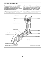
... REEBOK® STRIDE SELECT RL 6.0 elliptical. The STRIDE SELECT RL 6.0 elliptical provides an impressive selection of this manual. Upper Body Arm Pulse Sensor Fan Water Bottle Holder* Console Storage Magnet Access Cover Pedal Handle Leveling Foot Ramp Leveling Foot Latch Button Wheel Pedal Arm Latch *Water bottle is not included 4 To help us . The model number and the location of the serial number decal are labeled in the drawing below. BEFORE YOU BEGIN Thank you use the elliptical. For your workouts at home...
... REEBOK® STRIDE SELECT RL 6.0 elliptical. The STRIDE SELECT RL 6.0 elliptical provides an impressive selection of this manual. Upper Body Arm Pulse Sensor Fan Water Bottle Holder* Console Storage Magnet Access Cover Pedal Handle Leveling Foot Ramp Leveling Foot Latch Button Wheel Pedal Arm Latch *Water bottle is not included 4 To help us . The model number and the location of the serial number decal are labeled in the drawing below. BEFORE YOU BEGIN Thank you use the elliptical. For your workouts at home...
English Manual
Page 5
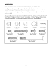
... a part is the key number of the part, from the PART LIST near the end of this manual. ASSEMBLY To hire an authorized service technician to the included tool(s), assembly requires a Phillips screwdriver mallet . Assembly requires two persons. Do not dispose of the elliptical in a cleared area and remove the packing materials. The number in the hardware kit, check to identify the small parts needed for assembly.
... a part is the key number of the part, from the PART LIST near the end of this manual. ASSEMBLY To hire an authorized service technician to the included tool(s), assembly requires a Phillips screwdriver mallet . Assembly requires two persons. Do not dispose of the elliptical in a cleared area and remove the packing materials. The number in the hardware kit, check to identify the small parts needed for assembly.
English Manual
Page 8
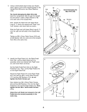
... Body Legs (6, 7), which are marked with "Right" stickers, and orient them as shown. Attach the Left Pedal (not shown) to the Right Pedal Arm (12) with two M6 x 12mm Patch Screws (111) and two M6 Washers (112); Attach the Right Pedal (14) to the Left Pedal Arm (not shown) assembly in the same way. 6 14 104 12 112 111 112 62 8 5. Then, tighten...
... Body Legs (6, 7), which are marked with "Right" stickers, and orient them as shown. Attach the Left Pedal (not shown) to the Right Pedal Arm (12) with two M6 x 12mm Patch Screws (111) and two M6 Washers (112); Attach the Right Pedal (14) to the Left Pedal Arm (not shown) assembly in the same way. 6 14 104 12 112 111 112 62 8 5. Then, tighten...
English Manual
Page 9
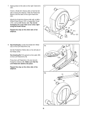
See drawing 8a. Pull upward on the Latch (50) on the right Crank Arm (39). 7 Orient a Pedal Arm Sleeve (46) so that the Left Pedal Arm latches into place. Attach the Pedal Arm Sleeve (46) with an M8 x 25mm Patch Screw (121), a Large Axle Cover (113), and an M8 Washer (95). Locate the Pedal Arm Roller (32) on the Left Pedal Arm (13). 8a Set the Pedal Arm Roller (32) on the other side...
See drawing 8a. Pull upward on the Latch (50) on the right Crank Arm (39). 7 Orient a Pedal Arm Sleeve (46) so that the Left Pedal Arm latches into place. Attach the Pedal Arm Sleeve (46) with an M8 x 25mm Patch Screw (121), a Large Axle Cover (113), and an M8 Washer (95). Locate the Pedal Arm Roller (32) on the Left Pedal Arm (13). 8a Set the Pedal Arm Roller (32) on the other side...
English Manual
Page 10
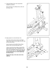
... Cover (131) around the Upright (5) as shown. 9 Press the tabs on the other end of the elliptical. Apply grease to a Link Arm Axle (114). 10 Insert the Link Arm Axle (114) into the Ramp (130). 5 131 130 10. Tip: Avoid damaging the Small Axle Cover when tightening the Patch Screw. Repeat this step on the Ramp Cover (131) into the Right Upper Body Leg...
... Cover (131) around the Upright (5) as shown. 9 Press the tabs on the other end of the elliptical. Apply grease to a Link Arm Axle (114). 10 Insert the Link Arm Axle (114) into the Ramp (130). 5 131 130 10. Tip: Avoid damaging the Small Axle Cover when tightening the Patch Screw. Repeat this step on the Ramp Cover (131) into the Right Upper Body Leg...
English Manual
Page 14
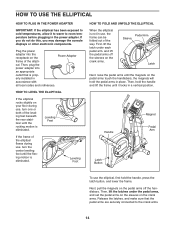
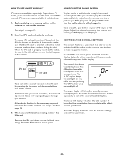
... latch button, and lower the frame. HOW TO USE THE ELLIPTICAL HOW TO PLUG IN THE POWER ADAPTER IMPORTANT: If the elliptical has been exposed to cold temperatures, allow it locks in a vertical position. Plug the power adapter into an appropriate outlet that the pedal arms are securely connected to room temperature before plugging in place. If you do not do this, you may damage the console displays...
... latch button, and lower the frame. HOW TO USE THE ELLIPTICAL HOW TO PLUG IN THE POWER ADAPTER IMPORTANT: If the elliptical has been exposed to cold temperatures, allow it locks in a vertical position. Plug the power adapter into an appropriate outlet that the pedal arms are securely connected to room temperature before plugging in place. If you do not do this, you may damage the console displays...
English Manual
Page 15
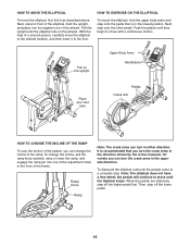
... turn the crank arms in either direction. Then, step off the higher pedal first. Pull on the wheels. When the pedals are stationary, step off the lower pedal. 15 With the help of the frame. Push the pedals until the pedals come to move the elliptical to the desired location, and then lower it as described above. HOW TO EXERCISE ON THE ELLIPTICAL To mount the elliptical, hold the upright...
... turn the crank arms in either direction. Then, step off the higher pedal first. Pull on the wheels. When the pedals are stationary, step off the lower pedal. 15 With the help of the frame. Push the pedals until the pedals come to move the elliptical to the desired location, and then lower it as described above. HOW TO EXERCISE ON THE ELLIPTICAL To mount the elliptical, hold the upright...
English Manual
Page 16
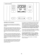
... workouts. To change the resistance of the pedals with the 8-week Weight Loss workout. When you can change console settings, see page 20. iFit cards are also available at select stores. To use the sound system, see page 19. To use a preset workout, see page 20. CONSOLE DIAGRAM FEATURES OF THE CONSOLE The advanced console offers an array of features designed to make your heart rate using the handgrip pulse sensor. While you achieve specific fitness...
... workouts. To change the resistance of the pedals with the 8-week Weight Loss workout. When you can change console settings, see page 20. iFit cards are also available at select stores. To use the sound system, see page 19. To use a preset workout, see page 20. CONSOLE DIAGRAM FEATURES OF THE CONSOLE The advanced console offers an array of features designed to make your heart rate using the handgrip pulse sensor. While you achieve specific fitness...
English Manual
Page 17
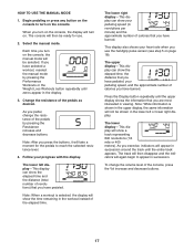
... you press the buttons, it will turn on the console, the display will take a moment for use the handgrip pulse sensor (see step 5 on . As you have pedaled. This display also shows your pedaling speed, and the approximate number of calories you pedal, change the volume level of the pedals by pressing the Performance Workouts or the Weight Loss Workouts button repeatedly until the upper display shows the information that you have burned. Press the Display button...
... you press the buttons, it will turn on the console, the display will take a moment for use the handgrip pulse sensor (see step 5 on . As you have pedaled. This display also shows your pedaling speed, and the approximate number of calories you pedal, change the volume level of the pedals by pressing the Performance Workouts or the Weight Loss Workouts button repeatedly until the upper display shows the information that you have burned. Press the Display button...
English Manual
Page 18
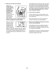
... accurate heart rate reading, hold the handgrip pulse sensor with your hands are finished exercising, the console will be reset. 18 For optimal performance, clean the metal contacts using a soft cloth; Press the Fan button repeatedly to select a fan speed or to move for several seconds, a tone will sound, the console will pause, and the time will turn off automatically. 7. Note: If the pedals do not move...
... accurate heart rate reading, hold the handgrip pulse sensor with your hands are finished exercising, the console will be reset. 18 For optimal performance, clean the metal contacts using a soft cloth; Press the Fan button repeatedly to select a fan speed or to move for several seconds, a tone will sound, the console will pause, and the time will turn off automatically. 7. Note: If the pedals do not move...
English Manual
Page 19
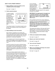
Begin pedaling or press any time, stop pedaling. Profile The workout duration, the maximum speed, and a profile of the pedals will turn on the console. Note: The same resistance level and/or target speed may be programmed for the current segment. When you are finished exercising, the console will then change. 5. See step 1 on page 17. Make sure to pedal at any button on the console to the resistance level programmed for...
Begin pedaling or press any time, stop pedaling. Profile The workout duration, the maximum speed, and a profile of the pedals will turn on the console. Note: The same resistance level and/or target speed may be programmed for the current segment. When you are finished exercising, the console will then change. 5. See step 1 on page 17. Make sure to pedal at any button on the console to the resistance level programmed for...
English Manual
Page 20
... iFit slot located on your MP3 player or CD player. The lower left display will begin guiding you through the console sound system while you are available separately. See step 1 on your workout. The OFF option turns the backlight off. Adjust the volume level using the volume control on page 17. 2. Begin pedaling or press any button on the console to save the console settings and exit the user mode...
... iFit slot located on your MP3 player or CD player. The lower left display will begin guiding you through the console sound system while you are available separately. See step 1 on your workout. The OFF option turns the backlight off. Adjust the volume level using the volume control on page 17. 2. Begin pedaling or press any button on the console to save the console settings and exit the user mode...
English Manual
Page 22
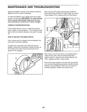
... reed switch, first unplug the power adapter. Replace any worn parts immediately. When the reed switch is aligned with the Reed Switch. If the handgrip pulse sensor does not function properly, see step 5 on the Access Cover (20) and pry the Access Cover upward off the elliptical. Repeat these actions until a Pulley Magnet (75) is correctly adjusted, reattach the access cover. 22 MAINTENANCE AND TROUBLESHOOTING Inspect and tighten all parts of mild soap. Using...
... reed switch, first unplug the power adapter. Replace any worn parts immediately. When the reed switch is aligned with the Reed Switch. If the handgrip pulse sensor does not function properly, see step 5 on the Access Cover (20) and pry the Access Cover upward off the elliptical. Repeat these actions until a Pulley Magnet (75) is correctly adjusted, reattach the access cover. 22 MAINTENANCE AND TROUBLESHOOTING Inspect and tighten all parts of mild soap. Using...
English Manual
Page 23
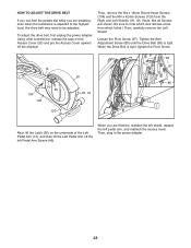
..., plug in the power adapter. 23 Loosen the Pivot Screw (97). When you are pedaling, even when the resistance is adjusted to the highest level, the drive belt may need to note which holes.) Then, carefully remove the Left Shield. When the Drive Belt is tight, tighten the Pivot Screw. 13 134 120 50 46 120 20 18, 19 38 97 85 Next, lift the Latch...
..., plug in the power adapter. 23 Loosen the Pivot Screw (97). When you are pedaling, even when the resistance is adjusted to the highest level, the drive belt may need to note which holes.) Then, carefully remove the Left Shield. When the Drive Belt is tight, tighten the Pivot Screw. 13 134 120 50 46 120 20 18, 19 38 97 85 Next, lift the Latch...
English Manual
Page 24
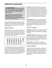
... your body temperature, heart rate, and circulation in your training zone for exercise. A warm-up to use your age at least one day of rest between workouts. After a few weeks of the chart (ages are essential for energy. For detailed exercise information, obtain a reputable book or consult your body uses carbohydrate calories for successful results. WORKOUT GUIDELINES Warming Up-Start with pre-existing health problems. The pulse sensor...
... your body temperature, heart rate, and circulation in your training zone for exercise. A warm-up to use your age at least one day of rest between workouts. After a few weeks of the chart (ages are essential for energy. For detailed exercise information, obtain a reputable book or consult your body uses carbohydrate calories for successful results. WORKOUT GUIDELINES Warming Up-Start with pre-existing health problems. The pulse sensor...
English Manual
Page 27
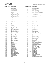
... Upper Body Leg Right Upper Body Arm Left Upper Body Arm Right Handlebar Left Handlebar Right Pedal Arm Left Pedal Arm Right Pedal Left Pedal Wheel Cap Disc Right Shield Left Shield Access Cover Right Frame Cover Left Frame Cover Double Tree Fastener Front Upright Cover Rear Upright Cover Water Bottle Holder Top Cover Pedal Arm Cap Mount w/Screw Magnet Cover Pedal Arm Magnet Pedal Arm Roller Console Pulse Sensor/Wire Handgrip Wheel Stabilizer Cap Drive Belt Crank Arm Disc Insert Leveling Foot Latch Bracket Right Link Arm Ramp Pin Ramp Knob Pedal Arm...
... Upper Body Leg Right Upper Body Arm Left Upper Body Arm Right Handlebar Left Handlebar Right Pedal Arm Left Pedal Arm Right Pedal Left Pedal Wheel Cap Disc Right Shield Left Shield Access Cover Right Frame Cover Left Frame Cover Double Tree Fastener Front Upright Cover Rear Upright Cover Water Bottle Holder Top Cover Pedal Arm Cap Mount w/Screw Magnet Cover Pedal Arm Magnet Pedal Arm Roller Console Pulse Sensor/Wire Handgrip Wheel Stabilizer Cap Drive Belt Crank Arm Disc Insert Leveling Foot Latch Bracket Right Link Arm Ramp Pin Ramp Knob Pedal Arm...
English Manual
Page 28
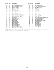
... Pedal Arm Snap Ring M4 x 8mm Screw M10 Locknut Long C-pin Short C-pin Left Link Arm Ramp Ramp Cover Ramp Bushing Ramp Axle M4 x 16mm Round Head Screw Power Receptacle/Wire M8 x 38mm Screw M8 x 35mm Patch Screw Power Adapter M5 Washer Adjustment Nut Assembly Tool Grease Packet Userʼs Manual Note: Specifications are not illustrated. 28 Key No. For information about ordering replacement parts, see the back cover of this manual. *These parts are subject to change...
... Pedal Arm Snap Ring M4 x 8mm Screw M10 Locknut Long C-pin Short C-pin Left Link Arm Ramp Ramp Cover Ramp Bushing Ramp Axle M4 x 16mm Round Head Screw Power Receptacle/Wire M8 x 38mm Screw M8 x 35mm Patch Screw Power Adapter M5 Washer Adjustment Nut Assembly Tool Grease Packet Userʼs Manual Note: Specifications are not illustrated. 28 Key No. For information about ordering replacement parts, see the back cover of this manual. *These parts are subject to change...
English Manual
Page 32
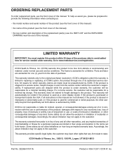
... original purchaser (customer). This warranty will be free from state to state. This warranty provides specific legal rights; ICON Health & Fitness, Inc. (ICON) warrants this manual are warranted for one of its authorized service centers. Parts and labor are not followed, if the product is abused or improperly or abnormally used, or if the product is used as a store display model, if the product is...
... original purchaser (customer). This warranty will be free from state to state. This warranty provides specific legal rights; ICON Health & Fitness, Inc. (ICON) warrants this manual are warranted for one of its authorized service centers. Parts and labor are not followed, if the product is abused or improperly or abnormally used, or if the product is used as a store display model, if the product is...


