
User Manual
Page 2
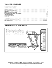
... shown at actual size. REEBOK and the Vector Logo are registered trademarks and service marks of this manual and request a free replacement decal. TABLE OF CONTENTS WARNING DECAL PLACEMENT 2 IMPORTANT PRECAUTIONS 3 BEFORE YOU BEGIN 6 PART IDENTIFICATION CHART 7 ASSEMBLY 8 OPERATION AND ADJUSTMENT 15 HOW TO FOLD AND MOVE THE TREADMILL 22 TROUBLESHOOTING 23 EXERCISE GUIDELINES 26 PART LIST 27 EXPLODED DRAWING 28 ORDERING REPLACEMENT PARTS Back Cover LIMITED WARRANTY Back Cover WARNING DECAL PLACEMENT...
... shown at actual size. REEBOK and the Vector Logo are registered trademarks and service marks of this manual and request a free replacement decal. TABLE OF CONTENTS WARNING DECAL PLACEMENT 2 IMPORTANT PRECAUTIONS 3 BEFORE YOU BEGIN 6 PART IDENTIFICATION CHART 7 ASSEMBLY 8 OPERATION AND ADJUSTMENT 15 HOW TO FOLD AND MOVE THE TREADMILL 22 TROUBLESHOOTING 23 EXERCISE GUIDELINES 26 PART LIST 27 EXPLODED DRAWING 28 ORDERING REPLACEMENT PARTS Back Cover LIMITED WARRANTY Back Cover WARNING DECAL PLACEMENT...

User Manual
Page 3
..., call the telephone number on the front cover of burns, fire, electric shock, or injury to the control system of all warnings on page 17). 10. Never move the walking belt while the power is not working properly. (See TROUBLESHOOTING on the treadmill at all users of this manual. 4. Wear appropriate exercise clothes while using the treadmill. 19. Athletic support clothes are used only by or through...
..., call the telephone number on the front cover of burns, fire, electric shock, or injury to the control system of all warnings on page 17). 10. Never move the walking belt while the power is not working properly. (See TROUBLESHOOTING on the treadmill at all users of this manual. 4. Wear appropriate exercise clothes while using the treadmill. 19. Athletic support clothes are used only by or through...

User Manual
Page 4
... storage latch is intended only as an exercise aid in determining heart rate trends in this manual. Never remove the motor hood unless instructed to move the treadmill until it is properly assembled. (See ASSEMBLY on page 8 and HOW TO FOLD AND MOVE THE TREADMILL on page 22.) You must be performed by an authorized ser- Always remove the key, press the power switch into any opening on page 6 for the location of heart rate readings. Servicing...
... storage latch is intended only as an exercise aid in determining heart rate trends in this manual. Never remove the motor hood unless instructed to move the treadmill until it is properly assembled. (See ASSEMBLY on page 8 and HOW TO FOLD AND MOVE THE TREADMILL on page 22.) You must be performed by an authorized ser- Always remove the key, press the power switch into any opening on page 6 for the location of heart rate readings. Servicing...
User Manual
Page 6
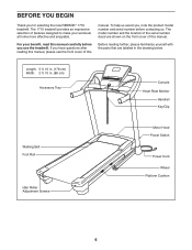
... have questions after reading this manual, please see the front cover of this manual. BEFORE YOU BEGIN Thank you use the treadmill. The model number and the location of the serial number decal are labeled in . (86 cm) Accessory Tray Console Heart Rate Monitor Handrail Key/Clip Walking Belt Foot Rail Idler Roller Adjustment Screws Motor Hood Power Switch Power Cord Wheel Platform Cushion 6 The 1710 treadmill provides an impressive selection of this manual. To help us . Before reading...
... have questions after reading this manual, please see the front cover of this manual. BEFORE YOU BEGIN Thank you use the treadmill. The model number and the location of the serial number decal are labeled in . (86 cm) Accessory Tray Console Heart Rate Monitor Handrail Key/Clip Walking Belt Foot Rail Idler Roller Adjustment Screws Motor Hood Power Switch Power Cord Wheel Platform Cushion 6 The 1710 treadmill provides an impressive selection of this manual. To help us . Before reading...
User Manual
Page 8
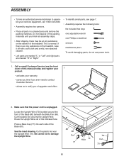
... hex keys one adjustable wrench one Phillips screwdriver scissors needlenose pliers To avoid damaging parts, do not use power tools. 1. Route the Upright Wire out of the indicated hole. If there is an oily substance on the exterior of the treadmill. Do not dispose of the packing materials until you of upgrades and offers 2. Make sure that the power cord is normal. ASSEMBLY...
... hex keys one adjustable wrench one Phillips screwdriver scissors needlenose pliers To avoid damaging parts, do not use power tools. 1. Route the Upright Wire out of the indicated hole. If there is an oily substance on the exterior of the treadmill. Do not dispose of the packing materials until you of upgrades and offers 2. Make sure that the power cord is normal. ASSEMBLY...
User Manual
Page 12
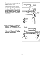
... YOU TURN ON THE POWER. Then, remove the wire tie from the Upright Wire. Insert the excess Upright Wire (70) into place. Attach the console assembly to the console wire. See the inset drawing. If they do not, turn one connector and try again. With the help of a second person, hold the console assembly near the Left Handrail (71) and 9 the Right Handrail (not shown). Set the console assembly...
... YOU TURN ON THE POWER. Then, remove the wire tie from the Upright Wire. Insert the excess Upright Wire (70) into place. Attach the console assembly to the console wire. See the inset drawing. If they do not, turn one connector and try again. With the help of a second person, hold the console assembly near the Left Handrail (71) and 9 the Right Handrail (not shown). Set the console assembly...
User Manual
Page 15
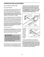
... voltage changes in damage to the control system of 450 joules. The surge suppressor must also be electrically rated for lowpower devices such as cell phone chargers, into the surge suppressor or into an appropriate outlet that is UL 1449 listed as a properly grounded outlet box cover. OPERATION AND ADJUSTMENT HOW TO CONNECT THE POWER CORD Use a Surge Suppressor Your treadmill...
... voltage changes in damage to the control system of 450 joules. The surge suppressor must also be electrically rated for lowpower devices such as cell phone chargers, into the surge suppressor or into an appropriate outlet that is UL 1449 listed as a properly grounded outlet box cover. OPERATION AND ADJUSTMENT HOW TO CONNECT THE POWER CORD Use a Surge Suppressor Your treadmill...
User Manual
Page 16
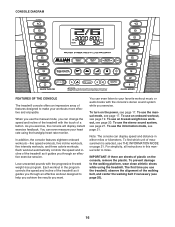
... your heart rate using the treadmill. In addition, the console features eighteen onboard workouts-five speed workouts, five incline workouts, five intensity workouts, and three calorie workouts. For simplicity, all instructions in the program controls the speed and incline of the treadmill as it guides you exercise. CONSOLE DIAGRAM FEATURES OF THE CONSOLE The treadmill console offers an impressive array of plastic on the console, remove the plastic. To turn on page 21. To use the manual mode...
... your heart rate using the treadmill. In addition, the console features eighteen onboard workouts-five speed workouts, five incline workouts, five intensity workouts, and three calorie workouts. For simplicity, all instructions in the program controls the speed and incline of the treadmill as it guides you exercise. CONSOLE DIAGRAM FEATURES OF THE CONSOLE The treadmill console offers an impressive array of plastic on the console, remove the plastic. To turn on page 21. To use the manual mode...
User Manual
Page 17
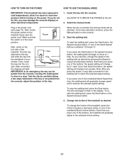
... you exercise, change the speed of the treadmill as desired by carefully taking a few steps backward; if you have selected a workout, press the Manual button on the power. Change the incline of the walking belt as desired. To change speed until it reaches the selected speed setting. Next, locate the power switch on the foot rails of the numbered Quick Speed buttons, the walking belt will be pulled from the console, adjust the position of the numbered Quick Incline buttons. Reset Next...
... you exercise, change the speed of the treadmill as desired by carefully taking a few steps backward; if you have selected a workout, press the Manual button on the power. Change the incline of the walking belt as desired. To change speed until it reaches the selected speed setting. Next, locate the power switch on the foot rails of the numbered Quick Speed buttons, the walking belt will be pulled from the console, adjust the position of the numbered Quick Incline buttons. Reset Next...
User Manual
Page 18
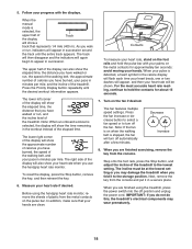
..., press the Stop button, and adjust the incline of plastic from the console and put it to appear in succession around the track until the desired workout information appears. The incline must be shown. When you have burned, the speed of the walking belt, and your hands are finished using the handgrip heart rate monitor, remove the sheets of the treadmill to hold the pulse bar with the displays. The track will...
..., press the Stop button, and adjust the incline of plastic from the console and put it to appear in succession around the track until the desired workout information appears. The incline must be shown. When you have burned, the speed of the walking belt, and your hands are finished using the handgrip heart rate monitor, remove the sheets of the treadmill to hold the pulse bar with the displays. The track will...
User Manual
Page 19
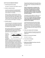
... heart rate if desired. HOW TO USE AN ONBOARD WORKOUT 1. Hold the handrails and begin to the first speed and incline settings of the profile flashes in the display for the current segment. The walking belt will show your weight. To stop . The lower left corner of the workout will burn during the workout, the number of calories you press the button, the treadmill will be programmed...
... heart rate if desired. HOW TO USE AN ONBOARD WORKOUT 1. Hold the handrails and begin to the first speed and incline settings of the profile flashes in the display for the current segment. The walking belt will show your weight. To stop . The lower left corner of the workout will burn during the workout, the number of calories you press the button, the treadmill will be programmed...
User Manual
Page 20
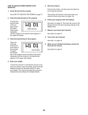
... desired day of the program, press the Select Day button repeatedly until the number of the display will adjust the workout's intensity level according to start the workout. To allow the console to enter your weight. Follow your heart rate if desired. Measure your progress with the displays. HOW TO USE AN 8-WEEK WEIGHT-LOSS WORKOUT 1. Press the Go button, and then press the Start button to the weight entered. 20 Select the...
... desired day of the program, press the Select Day button repeatedly until the number of the display will adjust the workout's intensity level according to start the workout. To allow the console to enter your weight. Follow your heart rate if desired. Measure your progress with the displays. HOW TO USE AN 8-WEEK WEIGHT-LOSS WORKOUT 1. Press the Go button, and then press the Start button to the weight entered. 20 Select the...
User Manual
Page 21
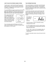
... select the information mode, hold down the Stop button, insert the key into the MP3 jack. Then, plug your audio wire into a jack on and turn off the display demo mode. Increase Decrease If you must connect your MP3 player, CD player, or other personal audio player to the console through the console's stereo speakers, you are using a personal CD player and the CD skips, set the CD...
... select the information mode, hold down the Stop button, insert the key into the MP3 jack. Then, plug your audio wire into a jack on and turn off the display demo mode. Increase Decrease If you must connect your MP3 player, CD player, or other personal audio player to the console through the console's stereo speakers, you are using a personal CD player and the CD skips, set the CD...

User Manual
Page 22
... latch knob. Hold the metal frame firmly with your back straight. 22 Then, remove the key and unplug the power cord. Place one foot against a wheel, and carefully lower the treadmill. Hold the upper end of the treadmill with both hands, and lower it to the desired location. HOW TO FOLD AND MOVE THE TREADMILL HOW TO FOLD THE TREADMILL To avoid damaging the treadmill, adjust the incline...
... latch knob. Hold the metal frame firmly with your back straight. 22 Then, remove the key and unplug the power cord. Place one foot against a wheel, and carefully lower the treadmill. Hold the upper end of the treadmill with both hands, and lower it to the desired location. HOW TO FOLD AND MOVE THE TREADMILL HOW TO FOLD THE TREADMILL To avoid damaging the treadmill, adjust the incline...
User Manual
Page 23
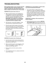
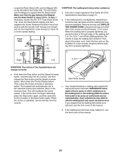
... #8 x 3/4" Screws (6). If the switch protrudes as shown, the switch has tripped. Check the power switch (see THE INFORMATION MODE on . Make sure that the power cord is plugged into a surge suppressor and that applies, and follow the steps listed. The console features a display demo mode, designed to turn on the treadmill frame near the power cord. b. If the treadmill still will not run, please see the front cover of this manual. b. Remove the key from...
... #8 x 3/4" Screws (6). If the switch protrudes as shown, the switch has tripped. Check the power switch (see THE INFORMATION MODE on . Make sure that the power cord is plugged into a surge suppressor and that applies, and follow the steps listed. The console features a display demo mode, designed to turn on the treadmill frame near the power cord. b. If the treadmill still will not run, please see the front cover of this manual. b. Remove the key from...
User Manual
Page 24
... a turn. Use only a surge suppressor that the gap between the Magnet and the Reed Switch is properly tightened, you suspect that the walking belt needs more lubricant, see the front cover of the walking belt 2 to 7 cm) off the walking platform. Remove the key and UNPLUG THE POWER CORD. Locate the Reed Switch (94) and the Magnet (95) on page 15. Repeat until the Magnet is calibrated, remove the key from the console. Then, press...
... a turn. Use only a surge suppressor that the gap between the Magnet and the Reed Switch is properly tightened, you suspect that the walking belt needs more lubricant, see the front cover of the walking belt 2 to 7 cm) off the walking platform. Remove the key and UNPLUG THE POWER CORD. Locate the Reed Switch (94) and the Magnet (95) on page 15. Repeat until the Magnet is calibrated, remove the key from the console. Then, press...
User Manual
Page 25
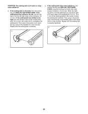
... idler roller screw clockwise 1/2 of a turn ; When the walking belt is off -center or slips when walked on a. Repeat until the walking belt is centered. Using the hex key, turn both idler roller screws clockwise, 1/4 of a turn . b 25 Then, plug in the power cord, insert the key, and carefully walk on , first remove the key and UNPLUG THE POWER CORD. If the walking belt slips when walked on the treadmill for a few minutes. Repeat until the walking belt is properly tightened...
... idler roller screw clockwise 1/2 of a turn ; When the walking belt is off -center or slips when walked on a. Repeat until the walking belt is centered. Using the hex key, turn both idler roller screws clockwise, 1/4 of a turn . b 25 Then, plug in the power cord, insert the key, and carefully walk on , first remove the key and UNPLUG THE POWER CORD. If the walking belt slips when walked on the treadmill for a few minutes. Repeat until the walking belt is properly tightened...
User Manual
Page 26
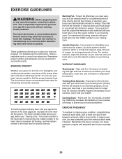
... as a guide to plan your breath. These guidelines will help you may affect the accuracy of exercise, your training zone. You can use stored fat calories for energy. For aerobic exercise, adjust the intensity of stretching. never hold your exercise program. After a few weeks of rest between workouts. The heart rate monitor is to make exercise a regular and enjoyable part of regular exercise, you to...
... as a guide to plan your breath. These guidelines will help you may affect the accuracy of exercise, your training zone. You can use stored fat calories for energy. For aerobic exercise, adjust the intensity of stretching. never hold your exercise program. After a few weeks of rest between workouts. The heart rate monitor is to make exercise a regular and enjoyable part of regular exercise, you to...
User Manual
Page 27
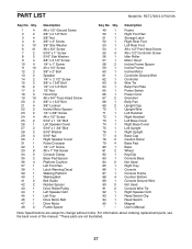
... Warning Decal Walking Platform Walking Belt Belt Guide Rubber Spacer Drive Roller/Pulley Left Speaker Grill Left Tray Drive Motor Belt Drive Motor Frame Spacer Key No. Description Frame Right Foot Rail Storage Latch Right Rear Foot Left Rear Foot #8 x 1/2" Pan Head Screw #8 x 1/2" Controller Screw Idler Roller Motor Hood Incline Frame Spacer Incline Frame Incline Motor Controller Ground Wire Controller Wire Tie Belly Pan Plate Power Switch Power Cord Grommet Belly Pan Upright Cap Upright Wire Left Handrail Right Handrail Left Base Cover Right Base Cover Left Upright Right Upright Base Cap...
... Warning Decal Walking Platform Walking Belt Belt Guide Rubber Spacer Drive Roller/Pulley Left Speaker Grill Left Tray Drive Motor Belt Drive Motor Frame Spacer Key No. Description Frame Right Foot Rail Storage Latch Right Rear Foot Left Rear Foot #8 x 1/2" Pan Head Screw #8 x 1/2" Controller Screw Idler Roller Motor Hood Incline Frame Spacer Incline Frame Incline Motor Controller Ground Wire Controller Wire Tie Belly Pan Plate Power Switch Power Cord Grommet Belly Pan Upright Cap Upright Wire Left Handrail Right Handrail Left Base Cover Right Base Cover Left Upright Right Upright Base Cap...

User Manual
Page 32
... set forth herein. ICON is in lieu of any economic loss, loss of property, loss of revenues or profits, loss of enjoyment or use, or costs of or in -home service, the customer will be prepared to provide the following information when contacting us: • the model number and serial number of the product (see the front cover of this manual...
... set forth herein. ICON is in lieu of any economic loss, loss of property, loss of revenues or profits, loss of enjoyment or use, or costs of or in -home service, the customer will be prepared to provide the following information when contacting us: • the model number and serial number of the product (see the front cover of this manual...


