User Guide & Warranty
Page 2
...user accessible parts. FCC Regulations state that unauthorized changes or modifications to this product to contact you need them. Also, make sure the stand or base you use only identical replacement parts Caution: To reduce the risk of the TV receiver and other surfaces. This could cause ... product for its proper operating voltage. Model No Serial No Purchase Date Dealer/Address/Phone The apparatus shall not be registered at www.rca.com/television. Special disposal of the unit will be required under the laws applicable to your attention to Article 820-40 of the ...
...user accessible parts. FCC Regulations state that unauthorized changes or modifications to this product to contact you need them. Also, make sure the stand or base you use only identical replacement parts Caution: To reduce the risk of the TV receiver and other surfaces. This could cause ... product for its proper operating voltage. Model No Serial No Purchase Date Dealer/Address/Phone The apparatus shall not be registered at www.rca.com/television. Special disposal of the unit will be required under the laws applicable to your attention to Article 820-40 of the ...

User Guide & Warranty
Page 3
... sure the antenna or cable system is grounded so as to qualified service personnel. Important Safety Instructions Important Safety Instructions 1. Use only with the cart, stand, tripod, bracket, or table specified by the manufacturer. 11. See following example. Keep these instructions. 2. Install in any way, such as radiators, heat registers, stoves...
... sure the antenna or cable system is grounded so as to qualified service personnel. Important Safety Instructions Important Safety Instructions 1. Use only with the cart, stand, tripod, bracket, or table specified by the manufacturer. 11. See following example. Keep these instructions. 2. Install in any way, such as radiators, heat registers, stoves...

User Guide & Warranty
Page 4
... Surges ...6 Instructions at the Beginning of User's Guide 6 Position Cables Properly to Avoid Audio Interference 6 Use Indirect Light ...6 Check Supplied Parts ...6 Attaching TV/DVD to Table Stand 7 Mounting TV/DVD to Wall ...11 Get the Picture ...12 Getting Channels ...12 Choose Your Connections ...13 Composite Video Connection ...14 Component Video Connection ...14 HDMI...
... Surges ...6 Instructions at the Beginning of User's Guide 6 Position Cables Properly to Avoid Audio Interference 6 Use Indirect Light ...6 Check Supplied Parts ...6 Attaching TV/DVD to Table Stand 7 Mounting TV/DVD to Wall ...11 Get the Picture ...12 Getting Channels ...12 Choose Your Connections ...13 Composite Video Connection ...14 Component Video Connection ...14 HDMI...

User Guide & Warranty
Page 6
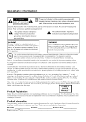
...8226; Turn off the TV/DVD and/or device(s) before you plug any power cords into the designated jack. • If you place devices above the TV, route all antennas and cables are presentation only. Refer to see the parts list for the table stand Graphics contained within this publication...outlet or power strip. Check Supplied Parts Check that air can circulate freely. • Don't stack devices. • If you place devices in a stand, make sure you allow adequate ventilation. • If you connect an audio receiver or amplifier, place it won't flow around other devices. REMOTE CONTROL...
...8226; Turn off the TV/DVD and/or device(s) before you plug any power cords into the designated jack. • If you place devices above the TV, route all antennas and cables are presentation only. Refer to see the parts list for the table stand Graphics contained within this publication...outlet or power strip. Check Supplied Parts Check that air can circulate freely. • Don't stack devices. • If you place devices in a stand, make sure you allow adequate ventilation. • If you connect an audio receiver or amplifier, place it won't flow around other devices. REMOTE CONTROL...
User Guide & Warranty
Page 7
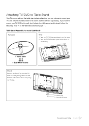
..., follow the Mounting Your TV to a wall (wall mount sold separately). Take the TV/DVD bag and place it face down on the TV bag. 1 Stand Table 3 Size M4 St-Screws Step 2 Remove the Stand Cap from the TV/ DVD cabinet by taking off the size M3 St-screw with a screwdriver and pulling out... the cap. Stand Cap Size M3 St-Screw Connections and Setup Chapter 1 7 Take the TV/DVD setand place it on page 11. Attaching TV/DVD to Table Stand Your TV comes without the table stand attached so that you want to mount your TV...
..., follow the Mounting Your TV to a wall (wall mount sold separately). Take the TV/DVD bag and place it face down on the TV bag. 1 Stand Table 3 Size M4 St-Screws Step 2 Remove the Stand Cap from the TV/ DVD cabinet by taking off the size M3 St-screw with a screwdriver and pulling out... the cap. Stand Cap Size M3 St-Screw Connections and Setup Chapter 1 7 Take the TV/DVD setand place it on page 11. Attaching TV/DVD to Table Stand Your TV comes without the table stand attached so that you want to mount your TV...

User Guide & Warranty
Page 8
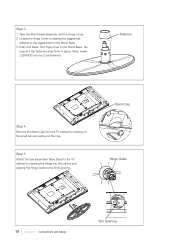
Step 3 Attach the table stand to the TV cabinet by inserting the stand into the stand connector support, and aligning the three screw holes, from the bottom, tightening three M4 St-screws with a screwdriver. Stand Connector Support 3 size M4 St-screws Swivel Table Stand Assembly for models L32HD33D and L40HD33D Parts List 1 Stand Table 1 Hinge for model L40HD33D 1 Hinge for model L32HD33D 1 Hinge Cover for model L40HD33D 1 Size M8 Screw 1 Hinge Cover for model L32HD33D 4 Size M5 Screws 8 Chapter 1 Connections and Setup
Step 3 Attach the table stand to the TV cabinet by inserting the stand into the stand connector support, and aligning the three screw holes, from the bottom, tightening three M4 St-screws with a screwdriver. Stand Connector Support 3 size M4 St-screws Swivel Table Stand Assembly for models L32HD33D and L40HD33D Parts List 1 Stand Table 1 Hinge for model L40HD33D 1 Hinge for model L32HD33D 1 Hinge Cover for model L40HD33D 1 Size M8 Screw 1 Hinge Cover for model L32HD33D 4 Size M5 Screws 8 Chapter 1 Connections and Setup

User Guide & Warranty
Page 9
Step 2 1. Position the Hinge by aligning the slot on the Hinge and the notch on the TV bag. Hinge Slot Notch x4 Connections and Setup Chapter 1 9 Attach the Hinge to the Stand Base with four Size M5 screws, from the bottom, with a Philips head #2 screwdriver. Take the TV set and place it on a flat table. 2. Step 1 1. Take the TV bag and place it face down on the Stand Base. 3. Take the Stand Base and the Hinge. 2.
Step 2 1. Position the Hinge by aligning the slot on the Hinge and the notch on the TV bag. Hinge Slot Notch x4 Connections and Setup Chapter 1 9 Attach the Hinge to the Stand Base with four Size M5 screws, from the bottom, with a Philips head #2 screwdriver. Take the TV set and place it on a flat table. 2. Step 1 1. Take the TV bag and place it face down on the Stand Base. 3. Take the Stand Base and the Hinge. 2.
User Guide & Warranty
Page 10
... Assembly and the Hinge Cover. 2. Step 5 Attach the fully assembled Table Stand to the TV cabinet by inserting the Hinge into the cabinet and aligning the Hinge Guide to the Stand Base. Stand Cap Hinge Guide 10 Chapter 1 Connections and Setup Slot Opening Push and fasten the Hinge Cover to the... Slot Opening. Locate the Hinge Cover by pushing on the Stand Base. 3. Be sure all 3 tab fasteners snap firmly in place. (Note: model L32HD33D only has 2 tab fasteners) Fastener Step 4 Remove the Stand Cap from the TV cabinet by aligning the biggest tab fastener to the biggest...
... Assembly and the Hinge Cover. 2. Step 5 Attach the fully assembled Table Stand to the TV cabinet by inserting the Hinge into the cabinet and aligning the Hinge Guide to the Stand Base. Stand Cap Hinge Guide 10 Chapter 1 Connections and Setup Slot Opening Push and fasten the Hinge Cover to the... Slot Opening. Locate the Hinge Cover by pushing on the Stand Base. 3. Be sure all 3 tab fasteners snap firmly in place. (Note: model L32HD33D only has 2 tab fasteners) Fastener Step 4 Remove the Stand Cap from the TV cabinet by aligning the biggest tab fastener to the biggest...
User Guide & Warranty
Page 11
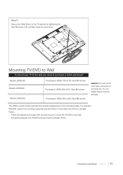
..., 600x400 means the mounting measurements are 600mm horizontally and 400mm vertically. Step 6 Secure the Table Stand to the TV cabinet by tightening the Size M8 screw with the wall mount to mount the TV/DVD to purchase a VESA wall mount Model L26HD33D Purchase a VESA 100 x100, Size M4 screw Model... L32HD33D Purchase a VESA 200 x100, Size M4 screw Model L40HD33D Purchase a VESA 600 x400, Size M6 screw Caution:Your wall mount ...
..., 600x400 means the mounting measurements are 600mm horizontally and 400mm vertically. Step 6 Secure the Table Stand to the TV cabinet by tightening the Size M8 screw with the wall mount to mount the TV/DVD to purchase a VESA wall mount Model L26HD33D Purchase a VESA 100 x100, Size M4 screw Model... L32HD33D Purchase a VESA 200 x100, Size M4 screw Model L40HD33D Purchase a VESA 600 x400, Size M6 screw Caution:Your wall mount ...

User Guide & Warranty
Page 18
how you move up or down arrow button to move through the on your choice and select it. Note: Highlighted means that the menu item stands out from the back of the remote by pushing the tab and lifting off the cover. • Insert two fresh batteries. Do not plug into ... selections for a menu choice or to view other end into the back of the TV or ON•OFF on the side of the TV/DVD. Use the right or left arrow button to display a sub-menu. 18 Chapter 1 Connections and Setup To highlight a menu item, press the arrow buttons on...
how you move up or down arrow button to move through the on your choice and select it. Note: Highlighted means that the menu item stands out from the back of the remote by pushing the tab and lifting off the cover. • Insert two fresh batteries. Do not plug into ... selections for a menu choice or to view other end into the back of the TV or ON•OFF on the side of the TV/DVD. Use the right or left arrow button to display a sub-menu. 18 Chapter 1 Connections and Setup To highlight a menu item, press the arrow buttons on...
Spec Sheet
Page 1
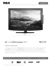
... room light to operate with stunning picture performance and sensible innovations. L40HD33D 40" LCD/DVD Combo HDTV Features and Benefits RCA introduces another High Definition LCD/DVD Combo television series, featuring the new RCA L40HD33D. Check with stand: 40.8 x 28.4 x 10.2 inches || w/o stand: 40.8 x 26 x 6 inches * Cable TV subscription required. The RCA L40HD33D features HDTV technology performance, a built-in your room's environment-night or day. Product...
... room light to operate with stunning picture performance and sensible innovations. L40HD33D 40" LCD/DVD Combo HDTV Features and Benefits RCA introduces another High Definition LCD/DVD Combo television series, featuring the new RCA L40HD33D. Check with stand: 40.8 x 28.4 x 10.2 inches || w/o stand: 40.8 x 26 x 6 inches * Cable TV subscription required. The RCA L40HD33D features HDTV technology performance, a built-in your room's environment-night or day. Product...
Spec Sheet
Page 2
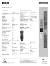
L40HD33D Specifications jack panels Side Panel Back Panel TECHNOLOGY Tuner Analog Video Formats (NTSC/480i) Video Formats (480p, 720p, 1080i) HDTV Capability Category ...with composite) INPUT LCD HDMI Inputs ** 2 V1.3 (1 DVI compatible) 40W 16:9 1366x768 450 3000:1 178/178 Audio input for Composite 1 HDMI Inputs ** USBY InpYut VIDEO 0 HDMI /DVI 2 1 - RCA and associated marks ...Warranty (E/F/S) Go to RCA.com/Television GENERAL TV Finish RS86A REAR AV OVERLAY Black RS86A REAR AV OVERLAY REW, Eject Stand Included (swivel) CD, CD-DA, CD-R/RW DVD, DVD-R/RW Video Format Only ...
L40HD33D Specifications jack panels Side Panel Back Panel TECHNOLOGY Tuner Analog Video Formats (NTSC/480i) Video Formats (480p, 720p, 1080i) HDTV Capability Category ...with composite) INPUT LCD HDMI Inputs ** 2 V1.3 (1 DVI compatible) 40W 16:9 1366x768 450 3000:1 178/178 Audio input for Composite 1 HDMI Inputs ** USBY InpYut VIDEO 0 HDMI /DVI 2 1 - RCA and associated marks ...Warranty (E/F/S) Go to RCA.com/Television GENERAL TV Finish RS86A REAR AV OVERLAY Black RS86A REAR AV OVERLAY REW, Eject Stand Included (swivel) CD, CD-DA, CD-R/RW DVD, DVD-R/RW Video Format Only ...

