
English Manual
Page 2
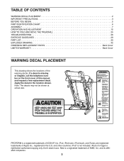
PROFORM is for legal or rightholder-authorized copying only. iPod, iPod nano, iPod touch, and iTunes are registered trademarks of Apple Inc., registered in the location ... not included. Don’'t steal music. TABLE OF CONTENTS WARNING DECAL PLACEMENT 2 IMPORTANT PRECAUTIONS 3 BEFORE YOU BEGIN 5 PART IDENTIFICATION CHART 6 ASSEMBLY 7 OPERATION AND ADJUSTMENT 15 HOW TO FOLD AND MOVE THE TREADMILL 25 TROUBLESHOOTING 26 EXERCISE GUIDELINES 29 PART LIST 30 EXPLODED DRAWING 32 ORDERING REPLACEMENT PARTS Back Cover LIMITED WARRANTY Back...
PROFORM is for legal or rightholder-authorized copying only. iPod, iPod nano, iPod touch, and iTunes are registered trademarks of Apple Inc., registered in the location ... not included. Don’'t steal music. TABLE OF CONTENTS WARNING DECAL PLACEMENT 2 IMPORTANT PRECAUTIONS 3 BEFORE YOU BEGIN 5 PART IDENTIFICATION CHART 6 ASSEMBLY 7 OPERATION AND ADJUSTMENT 15 HOW TO FOLD AND MOVE THE TREADMILL 25 TROUBLESHOOTING 26 EXERCISE GUIDELINES 29 PART LIST 30 EXPLODED DRAWING 32 ORDERING REPLACEMENT PARTS Back Cover LIMITED WARRANTY Back...
English Manual
Page 4
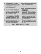
...page 5 for the location of heart rate readings. Over exercising may affect the accuracy of the power switch), and unplug the power cord when the treadmill is running. If you feel faint or if you experience pain while exercising, stop immediately and cool...ASSEMBLY on page 7 and HOW TO FOLD AND MOVE THE TREADMILL on page 25.) You must be performed by placing objects under the treadmill. 25. Never leave the treadmill unattended while it is holding the frame securely in general. 21. Do not change the incline of the treadmill regularly. Always remove the key, press the power...
...page 5 for the location of heart rate readings. Over exercising may affect the accuracy of the power switch), and unplug the power cord when the treadmill is running. If you feel faint or if you experience pain while exercising, stop immediately and cool...ASSEMBLY on page 7 and HOW TO FOLD AND MOVE THE TREADMILL on page 25.) You must be performed by placing objects under the treadmill. 25. Never leave the treadmill unattended while it is holding the frame securely in general. 21. Do not change the incline of the treadmill regularly. Always remove the key, press the power...

English Manual
Page 6
... the part, from the PART LIST near the end of this manual. The number in the hardware kit, check to identify small parts used for assembly. Extra parts may be included. 1/4" Star Washer (35)–-6 5/16" Flat Washer (68)–-4 5/16" Star Washer (11)–-4 3/8" ...;-2 3/8" x 1 1/4" Screw (8)–-4 3/8" x 1 3/4" Bolt (6)–-1 1/4" x 1/2" Screw (36)–-4 3/8" x 2" Bolt (3)–-1 3/8" x 2 3/4" Screw (7)–-4 6 The number following the key number is the quantity used for assembly. PART IDENTIFICATION CHART Use the drawings below each drawing is preattached.
... the part, from the PART LIST near the end of this manual. The number in the hardware kit, check to identify small parts used for assembly. Extra parts may be included. 1/4" Star Washer (35)–-6 5/16" Flat Washer (68)–-4 5/16" Star Washer (11)–-4 3/8" ...;-2 3/8" x 1 1/4" Screw (8)–-4 3/8" x 1 3/4" Bolt (6)–-1 1/4" x 1/2" Screw (36)–-4 3/8" x 2" Bolt (3)–-1 3/8" x 2 3/4" Screw (7)–-4 6 The number following the key number is the quantity used for assembly. PART IDENTIFICATION CHART Use the drawings below each drawing is preattached.
English Manual
Page 7
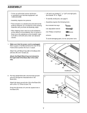
...x 3/4" Screws (2). ASSEMBLY •• To hire an authorized service technician to assemble your exercise equipment, call 1-800-445-2480. •• Assembly requires two persons. •• Place all assembly steps. •• After shipping, there may be an oily substance on the treadmill, wipe it off ...;• To identify small parts, see page 6. •• Assembly requires the following tools: the included hex keys one adjustable wrench one Phillips screwdriver scissors To avoid damaging parts, do not use power tools. 1. If there is unplugged. Attach the Left Wheel Cap ...
...x 3/4" Screws (2). ASSEMBLY •• To hire an authorized service technician to assemble your exercise equipment, call 1-800-445-2480. •• Assembly requires two persons. •• Place all assembly steps. •• After shipping, there may be an oily substance on the treadmill, wipe it off ...;• To identify small parts, see page 6. •• Assembly requires the following tools: the included hex keys one adjustable wrench one Phillips screwdriver scissors To avoid damaging parts, do not use power tools. 1. If there is unplugged. Attach the Left Wheel Cap ...
English Manual
Page 10
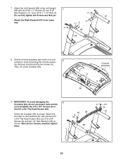
bly. Console Assembly A 93 9. Attach the Crossbar to the Handrails (87, 88) with two 5/16" x 1" Screws (5), two 5/16" Star Washers (11), and a 5/16" x 1 1/4" Bolt (4). IMPORTANT: To avoid damaging the 9 Crossbar (93), do not use power tools and do not overtighten the #10 x 3/4" Screws (9) or the #10 ... Remove and discard the two screws (A). Start all four Screws, and then tighten them. 63 93 9 35 88 9 63 35 87 10 Set the console assembly face down on a soft 8 surface to the Left Upright 7 (89) with two #10 x 3/4" Flat Head Screws (63), two #10 x 3/4"...
bly. Console Assembly A 93 9. Attach the Crossbar to the Handrails (87, 88) with two 5/16" x 1" Screws (5), two 5/16" Star Washers (11), and a 5/16" x 1 1/4" Bolt (4). IMPORTANT: To avoid damaging the 9 Crossbar (93), do not use power tools and do not overtighten the #10 x 3/4" Screws (9) or the #10 ... Remove and discard the two screws (A). Start all four Screws, and then tighten them. 63 93 9 35 88 9 63 35 87 10 Set the console assembly face down on a soft 8 surface to the Left Upright 7 (89) with two #10 x 3/4" Flat Head Screws (63), two #10 x 3/4"...
English Manual
Page 11
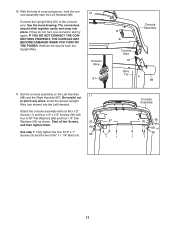
...the help of a second person, hold the console assembly near the Left Handrail (88). 10 Connect the Upright Wire (81) to pinch any wires. IF YOU DO NOT CONNECT THE CONNECTORS PROPERLY, THE CONSOLE MAY BECOME DAMAGED WHEN YOU TURN ON THE POWER. Be careful not 11 to the console wire.... Console Wire 81 Console Assembly Console Wire 81 Wire Tie 88 11. Set the console assembly on the Left Handrail (88) and the Right Handrail (87). Remove the wire...
...the help of a second person, hold the console assembly near the Left Handrail (88). 10 Connect the Upright Wire (81) to pinch any wires. IF YOU DO NOT CONNECT THE CONNECTORS PROPERLY, THE CONSOLE MAY BECOME DAMAGED WHEN YOU TURN ON THE POWER. Be careful not 11 to the console wire.... Console Wire 81 Console Assembly Console Wire 81 Wire Tie 88 11. Set the console assembly on the Left Handrail (88) and the Right Handrail (87). Remove the wire...

English Manual
Page 12
...) to the Right Upright (90) in the Left Upright (89). Slide the Right Handrail Cover 13 (86) onto the Right Handrail (87). Console 79 80 1 Assembly 1 1 90 89 12 Attach the Handrail Covers with three #8 x 1/2" Screws (1). Press the Left Base Cover (82) and the Right Base Cover (83) onto the Base... one 12 side is shown). Slide the Left Handrail Cover (85) onto the Left Handrail (88). Hold the Left Upright Cover (79) against the console assembly. Align the holes in the Left Upright 14 Cover with the holes in the same way.
...) to the Right Upright (90) in the Left Upright (89). Slide the Right Handrail Cover 13 (86) onto the Right Handrail (87). Console 79 80 1 Assembly 1 1 90 89 12 Attach the Handrail Covers with three #8 x 1/2" Screws (1). Press the Left Base Cover (82) and the Right Base Cover (83) onto the Base... one 12 side is shown). Slide the Left Handrail Cover (85) onto the Left Handrail (88). Hold the Left Upright Cover (79) against the console assembly. Align the holes in the Left Upright 14 Cover with the holes in the same way.

English Manual
Page 13
Attach the Left Tray (107) and the Right Tray (108) to follow all instructions in the power cord. Then, press the Incline increase button once. When the frame stops moving, remove the key from the console and unplug the power cord. IMPORTANT: See page 15 and plug in this step 13 IMPORTANT: Make sure to the console assembly with four #8 x 1/2" 15 Screws (1). 108 107 1 Console Assembly 1 1 16. Next, see page 17 and turn on 16 the power. 15.
Attach the Left Tray (107) and the Right Tray (108) to follow all instructions in the power cord. Then, press the Incline increase button once. When the frame stops moving, remove the key from the console and unplug the power cord. IMPORTANT: See page 15 and plug in this step 13 IMPORTANT: Make sure to the console assembly with four #8 x 1/2" 15 Screws (1). 108 107 1 Console Assembly 1 1 16. Next, see page 17 and turn on 16 the power. 15.


