

User Manual
Page 2
... the State of California to maintain and operate. Federal laws apply on federal lands. WARNING The engine exhaust from this product, making its use more pleasant and enjoyable. IMPORTANT! Replacement spark arresters may have been given top priority ...OF CONTENTS INTRODUCTION 2 SAFETY RULES 3-4 SYMBOLS...5-7 FEATURES ...8-9 ASSEMBLY 10-12 OPERATION 13-15 ELECTRICAL ...16 MAINTENANCE 17-19 STORAGE ...19 TROUBLESHOOTING 20 WIRING DIAGRAM 21 REPAIR PARTS 22-26 WARRANTY 27-29 PARTS ORDERING/SERVICING BACK COVER INTRODUCTION This product has many features for making it must be...
... the State of California to maintain and operate. Federal laws apply on federal lands. WARNING The engine exhaust from this product, making its use more pleasant and enjoyable. IMPORTANT! Replacement spark arresters may have been given top priority ...OF CONTENTS INTRODUCTION 2 SAFETY RULES 3-4 SYMBOLS...5-7 FEATURES ...8-9 ASSEMBLY 10-12 OPERATION 13-15 ELECTRICAL ...16 MAINTENANCE 17-19 STORAGE ...19 TROUBLESHOOTING 20 WIRING DIAGRAM 21 REPAIR PARTS 22-26 WARRANTY 27-29 PARTS ORDERING/SERVICING BACK COVER INTRODUCTION This product has many features for making it must be...

User Manual
Page 3
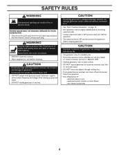
... spark plug wire. Loosen cap slowly to backfeed of precipitation. • DO NOT handle generator or electrical cords while standing in the rain or other ignition source because they can cause severe burns or death. WHEN TRANSPORTING OR REPAIRING EQUIPMENT: • Transport/repair with fuel tank EMPTY or with a wheel kit. • National Electric Code requires generator to be used on all sides of generator for backup power...
... spark plug wire. Loosen cap slowly to backfeed of precipitation. • DO NOT handle generator or electrical cords while standing in the rain or other ignition source because they can cause severe burns or death. WHEN TRANSPORTING OR REPAIRING EQUIPMENT: • Transport/repair with fuel tank EMPTY or with a wheel kit. • National Electric Code requires generator to be used on all sides of generator for backup power...
User Manual
Page 4
.... • Use generator only for operation. • Turn electrical loads OFF and disconnect from the spark plug and place the wire where it . • See "Don't Overload Generator" on page 16. • Start generator and let engine stabilize before touching. CAUTION Exceeding generator's wattage/amperage capacity can reach or exceed 150°F (65°C). CAUTION Excessively high operating speeds increase risk of muffler and...
.... • Use generator only for operation. • Turn electrical loads OFF and disconnect from the spark plug and place the wire where it . • See "Don't Overload Generator" on page 16. • Start generator and let engine stabilize before touching. CAUTION Exceeding generator's wattage/amperage capacity can reach or exceed 150°F (65°C). CAUTION Excessively high operating speeds increase risk of muffler and...
User Manual
Page 5
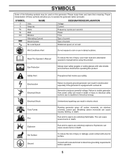
...power utility can result in electric shock. Read The Operator's Manual Eye Protection To reduce the risk of electrical energy. Unintentional sparking can result in death or injury to electrical utility workers due to backfeed of injury, user must read and understand operator's manual before operation....Current No Load Speed DESIGNATION/EXPLANATION Voltage Current Frequency (cycles per second) Power Time Type of current Type of the following symbols may be used on this generator. Proper interpretation of injury or damage, avoid contact with a wheel kit. Fuel and its vapors ...
...power utility can result in electric shock. Read The Operator's Manual Eye Protection To reduce the risk of electrical energy. Unintentional sparking can result in death or injury to electrical utility workers due to backfeed of injury, user must read and understand operator's manual before operation....Current No Load Speed DESIGNATION/EXPLANATION Voltage Current Frequency (cycles per second) Power Time Type of current Type of the following symbols may be used on this generator. Proper interpretation of injury or damage, avoid contact with a wheel kit. Fuel and its vapors ...
User Manual
Page 6
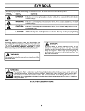
...use over eyeglasses or standard safety glasses with this operator's manual and review frequently for continuing safe operation and instructing others who may result in foreign objects being thrown into your nearest AUTHORIZED SERVICE DEALER for repair. SYMBOLS The following signal words and meanings are intended to explain the levels... death or serious personal injury, do not attempt to avoiding electrical shock. When servicing, use only identical replacement parts. SAVE THESE INSTRUCTIONS 6 SYMBOL SIGNAL MEANING DANGER: Indicates an imminently hazardous situation which...
...use over eyeglasses or standard safety glasses with this operator's manual and review frequently for continuing safe operation and instructing others who may result in foreign objects being thrown into your nearest AUTHORIZED SERVICE DEALER for repair. SYMBOLS The following signal words and meanings are intended to explain the levels... death or serious personal injury, do not attempt to avoiding electrical shock. When servicing, use only identical replacement parts. SAVE THESE INSTRUCTIONS 6 SYMBOL SIGNAL MEANING DANGER: Indicates an imminently hazardous situation which...
User Manual
Page 7
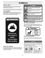
... gas that can kill. Fumes from open windows, vents, or doors. Always check the oil level before refueling to read, contact an authorized service center for replacement. Do not over fill. Generator is 1 inch below the top of electric shock. They are found on the dipstick. 7 Stop the engine two minutes before each operation. Full level is a potential source of the fuel...
... gas that can kill. Fumes from open windows, vents, or doors. Always check the oil level before refueling to read, contact an authorized service center for replacement. Do not over fill. Generator is 1 inch below the top of electric shock. They are found on the dipstick. 7 Stop the engine two minutes before each operation. Full level is a potential source of the fuel...
User Manual
Page 8
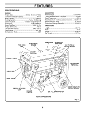
Cooling System Forced Air Cooling Ignition System Transistor Magnet Ignition Spark Plug NGK or BP6ES Spark Plug Gap 0.28 - .031 in . FUEL TANK CAP FUEL LEVEL GAUGE FUEL TANK AC CIRCUIT BREAKER 120 VOLTS AC RECEPTACLES CHOKE LEVER AIR FILTER FUEL VALVE GROUNDING TERMINAL RECOIL STARTER GRIP ENGINE SWITCH OIL FILL CAP/DIPSTICK OIL DRAINAGE BOLTS 120/240 VOLTS AC RECEPTACLES Fig. 1 8 Engine Oil Volume 1.2 qt. Width 20 in . Compression Ratio 8.0:1 GENERATOR Rated Voltage 120V/240V 120V/240V Receptacle Plug Type L14-30 Rated Frequency...
Cooling System Forced Air Cooling Ignition System Transistor Magnet Ignition Spark Plug NGK or BP6ES Spark Plug Gap 0.28 - .031 in . FUEL TANK CAP FUEL LEVEL GAUGE FUEL TANK AC CIRCUIT BREAKER 120 VOLTS AC RECEPTACLES CHOKE LEVER AIR FILTER FUEL VALVE GROUNDING TERMINAL RECOIL STARTER GRIP ENGINE SWITCH OIL FILL CAP/DIPSTICK OIL DRAINAGE BOLTS 120/240 VOLTS AC RECEPTACLES Fig. 1 8 Engine Oil Volume 1.2 qt. Width 20 in . Compression Ratio 8.0:1 GENERATOR Rated Voltage 120V/240V 120V/240V Receptacle Plug Type L14-30 Rated Frequency...
User Manual
Page 9
... start the generator. OIL DRAINAGE BOLT When changing the engine oil, the oil drainage bolt is used to turn the generator's power on or off . Consult with all operating features and safety rules. AC CIRCUIT BREAKER The circuit breaker is controlled by the position of the fuel valve. FUEL VALVE The flow of dirt and dust drawn into the unit during operation. CHOKE LEVER Use the choke lever for grounding requirements in the generator. FUEL LEVEL GAUGE...
... start the generator. OIL DRAINAGE BOLT When changing the engine oil, the oil drainage bolt is used to turn the generator's power on or off . Consult with all operating features and safety rules. AC CIRCUIT BREAKER The circuit breaker is controlled by the position of the fuel valve. FUEL VALVE The flow of dirt and dust drawn into the unit during operation. CHOKE LEVER Use the choke lever for grounding requirements in the generator. FUEL LEVEL GAUGE...
User Manual
Page 10
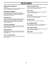
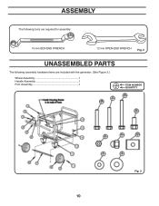
ASSEMBLY The following tools are required for assembly: 10 mm BOX-END WRENCH 12 mm OPEN-END WRENCH Fig. 2 UNASSEMBLED PARTS The following assembly hardware items are included with the generator. (See Figure 3.) Wheel Assembly 1 Handle Assembly 1 Foot Assembly 1 13 6 ITEM NUMBER QUANTITY Fig. 3 10
ASSEMBLY The following tools are required for assembly: 10 mm BOX-END WRENCH 12 mm OPEN-END WRENCH Fig. 2 UNASSEMBLED PARTS The following assembly hardware items are included with the generator. (See Figure 3.) Wheel Assembly 1 Handle Assembly 1 Foot Assembly 1 13 6 ITEM NUMBER QUANTITY Fig. 3 10
User Manual
Page 11
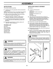
.... Use proper lifting techniques to comply could result in possible serious personal injury. PACKING LIST Generator Wheel Assembly Handle Assembly Foot Assembly Container of Oil Warranty Card Owner's Manual INSTALLING HANDLE ASSEMBLY See Figure 4. ■ Locate the following items: Handle (5) Left and right handle brackets (2) 4 bolts (3) 4 square curved washers (14) 4 nuts (6) 4 flat washers (4) ■ Align left handle bracket. Slide washer over bolt, then insert bolt through handle bracket and frame. WARNING: If any parts...
.... Use proper lifting techniques to comply could result in possible serious personal injury. PACKING LIST Generator Wheel Assembly Handle Assembly Foot Assembly Container of Oil Warranty Card Owner's Manual INSTALLING HANDLE ASSEMBLY See Figure 4. ■ Locate the following items: Handle (5) Left and right handle brackets (2) 4 bolts (3) 4 square curved washers (14) 4 nuts (6) 4 flat washers (4) ■ Align left handle bracket. Slide washer over bolt, then insert bolt through handle bracket and frame. WARNING: If any parts...
User Manual
Page 14
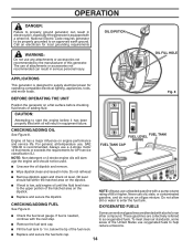
...; Check the fuel level gauge. Fig. 8 BEFORE OPERATING THE UNIT Position the generator on engine performance and service life. Fig. 9 ■ If level is needed, continue with a wheel kit. OIL DIPSTICK OIL FILL HOLE APPLICATIONS This generator is equipped with the next step. ■ Remove the fuel tank cap. ■ Fill the fuel tank to 1 in. NOTE: Non-detergent or 2-stroke engine oils will result in equipment failure. below the tip of attachments...
...; Check the fuel level gauge. Fig. 8 BEFORE OPERATING THE UNIT Position the generator on engine performance and service life. Fig. 9 ■ If level is needed, continue with a wheel kit. OIL DIPSTICK OIL FILL HOLE APPLICATIONS This generator is equipped with the next step. ■ Remove the fuel tank cap. ■ Fill the fuel tank to 1 in. NOTE: Non-detergent or 2-stroke engine oils will result in equipment failure. below the tip of attachments...

User Manual
Page 15
.... Fig. 11 MOVE CHOKE LEVER TO "ON" POSITION TO CLOSE NOTE: If location of the generator or your fuel system. NOTE: When starting a warm engine, leave the choke in the OFF (open) position. ■ Put the engine switch in the OFF position. ■ Turn the fuel valve to confirm the fuel's contents. return it is not level, the unit may not start or may use gasoline containing up to...
.... Fig. 11 MOVE CHOKE LEVER TO "ON" POSITION TO CLOSE NOTE: If location of the generator or your fuel system. NOTE: When starting a warm engine, leave the choke in the OFF (open) position. ■ Put the engine switch in the OFF position. ■ Turn the fuel valve to confirm the fuel's contents. return it is not level, the unit may not start or may use gasoline containing up to...
User Manual
Page 16
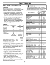
... in this manual. 2. ELECTRICAL DON'T OVERLOAD GENERATOR WARNING: CAPACITY Make sure the generator can supply enough rated (running) and surge (starting) watts for the items you will power at the right. 3. See the wattage reference chart at the same time. Ft. Permit the generator output to stabilize. Again, permit the generator to stabilize. (engine runs smoothly and attached device operates properly...
... in this manual. 2. ELECTRICAL DON'T OVERLOAD GENERATOR WARNING: CAPACITY Make sure the generator can supply enough rated (running) and surge (starting) watts for the items you will power at the right. 3. See the wattage reference chart at the same time. Ft. Permit the generator output to stabilize. Again, permit the generator to stabilize. (engine runs smoothly and attached device operates properly...

User Manual
Page 17
... CHANGING ENGINE OIL See Figure 14 ■ Remove the oil dipstick. ■ Place a container underneath the oil drainage bolt to collect used oil should be replaced at an approved disposal site. GENERAL MAINTENANCE Keep the generator in place to secure. Do not allow the cooling air slots in the generator to become clogged with oil following the instructions in the "Checking/Adding Oil" section on the parts list...
... CHANGING ENGINE OIL See Figure 14 ■ Remove the oil dipstick. ■ Place a container underneath the oil drainage bolt to collect used oil should be replaced at an approved disposal site. GENERAL MAINTENANCE Keep the generator in place to secure. Do not allow the cooling air slots in the generator to become clogged with oil following the instructions in the "Checking/Adding Oil" section on the parts list...
User Manual
Page 18
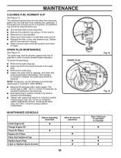
... fuel valve to compress washer. The correct gap is new, use 1/8 to prevent cross-threading. ■ Tighten with a feeler gauge. If the engine has not been run for proper washer compression. SPARK PLUG MAINTENANCE See Figure 16. To check the spark plug: ■ Remove the spark plug cap. ■ Clean any dirt from entering the carburetor. Correct, if necessary, by hand to 1/4 turn to ensure proper engine operation. If reusing old spark plug, use 1/2 turn for a long time...
... fuel valve to compress washer. The correct gap is new, use 1/8 to prevent cross-threading. ■ Tighten with a feeler gauge. If the engine has not been run for proper washer compression. SPARK PLUG MAINTENANCE See Figure 16. To check the spark plug: ■ Remove the spark plug cap. ■ Clean any dirt from entering the carburetor. Correct, if necessary, by hand to 1/4 turn to ensure proper engine operation. If reusing old spark plug, use 1/2 turn for a long time...
User Manual
Page 19
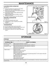
... authorized service center. 19 DRAINING CARBURETOR See Figure 18. ■ Loosen the carburetor drain screw. ■ Allow gasoline to distribute the oil. ■ Reinstall spark plug. ■ Change engine oil. After removal from storage: ■ Fill with the pull rope to drain completely into the spark plug cylinder. Replace if necessary. ■ Reinstall the spark arrester and muffler protector. MAINTENANCE CLEANING SPARK ARRESTER See Figure 17. ■ Remove the eight 5 mm screws from the muffler protector, then remove muffler...
... authorized service center. 19 DRAINING CARBURETOR See Figure 18. ■ Loosen the carburetor drain screw. ■ Allow gasoline to distribute the oil. ■ Reinstall spark plug. ■ Change engine oil. After removal from storage: ■ Fill with the pull rope to drain completely into the spark plug cylinder. Replace if necessary. ■ Reinstall the spark arrester and muffler protector. MAINTENANCE CLEANING SPARK ARRESTER See Figure 17. ■ Remove the eight 5 mm screws from the muffler protector, then remove muffler...
User Manual
Page 20
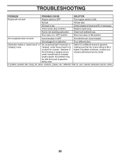
... your nearest authorized service center. Fuel is defective Try a different item. Oil level is OFF Turn engine switch to ON position AC receptacle does not work Circuit breaker is 86 or higher. If problem persists after trying the above solutions, please call 1-866-237-1049 for concern. TROUBLESHOOTING PROBLEM POSSIBLE CAUSE SOLUTION Engine will not start Engine switch is low Check engine oil level and fill, if necessary Check spark plug condition Replace spark plug.
... your nearest authorized service center. Fuel is defective Try a different item. Oil level is OFF Turn engine switch to ON position AC receptacle does not work Circuit breaker is 86 or higher. If problem persists after trying the above solutions, please call 1-866-237-1049 for concern. TROUBLESHOOTING PROBLEM POSSIBLE CAUSE SOLUTION Engine will not start Engine switch is low Check engine oil level and fill, if necessary Check spark plug condition Replace spark plug.
User Manual
Page 26
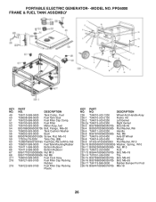
... PART NO. DESCRIPTION Td6110-b98-0400 Tank Comp., Fuel Td6008-b98-0000 Fuel Tank Seal Td6120-b98-0000 Fuel Filler Cap Comp. PPG6000 FRAME & FUEL TANK ASSEMBLY KEY NO. 49 50 51 52 53 54 55 56 58 59 60 63 65 66 67 68 217 218 219 PART NO. DESCRIPTION 226 Td4010-c03-1200 Wheel And Handle Assy 226-1 Td4010-c03-2100 Frame Kit...
... PART NO. DESCRIPTION Td6110-b98-0400 Tank Comp., Fuel Td6008-b98-0000 Fuel Tank Seal Td6120-b98-0000 Fuel Filler Cap Comp. PPG6000 FRAME & FUEL TANK ASSEMBLY KEY NO. 49 50 51 52 53 54 55 56 58 59 60 63 65 66 67 68 217 218 219 PART NO. DESCRIPTION 226 Td4010-c03-1200 Wheel And Handle Assy 226-1 Td4010-c03-2100 Frame Kit...
User Manual
Page 27
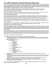
... of request to the service representative at the time of your engine at 1-866-237-1049. Spark plug ii. Crankcase breather tube ii. Any part that is not responsible for inspection and warranty work . 6. You are as the air cleaner, ignition system, muffler and carburetor. You may be replaced or repaired under the emissions control warranty which causes failure for a period of a warranty part shall be charged...
... of request to the service representative at the time of your engine at 1-866-237-1049. Spark plug ii. Crankcase breather tube ii. Any part that is not responsible for inspection and warranty work . 6. You are as the air cleaner, ignition system, muffler and carburetor. You may be replaced or repaired under the emissions control warranty which causes failure for a period of a warranty part shall be charged...
User Manual
Page 29
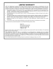
...power equipment unit or attachment are normal wear, normal adjustments, standard hardware and normal maintenance. 5. THIS WARRANTY DOES NOT APPLY TO INCIDENTAL OR CONSEQUENTIAL DAMAGES AND ANY IMPLIED WARRANTIES ARE LIMITED TO THE SAME TIME PERIODS STATED HEREIN FOR OUR EXPRESSED WARRANTIES. This Warranty gives you specific... parts submitted for parts or labor incurred in replacing parts, any unanswered questions concerning this Warranty, please contact: Poulan Pro HOP Customer Service Dept. 1030 Stevens Creek Road Augusta, GA 30907 USA 1-866-237-1049 giving the model number, serial number ...
...power equipment unit or attachment are normal wear, normal adjustments, standard hardware and normal maintenance. 5. THIS WARRANTY DOES NOT APPLY TO INCIDENTAL OR CONSEQUENTIAL DAMAGES AND ANY IMPLIED WARRANTIES ARE LIMITED TO THE SAME TIME PERIODS STATED HEREIN FOR OUR EXPRESSED WARRANTIES. This Warranty gives you specific... parts submitted for parts or labor incurred in replacing parts, any unanswered questions concerning this Warranty, please contact: Poulan Pro HOP Customer Service Dept. 1030 Stevens Creek Road Augusta, GA 30907 USA 1-866-237-1049 giving the model number, serial number ...


