
User Manual
Page 2
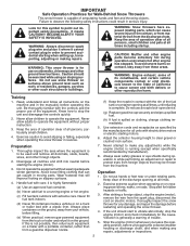
...the engine (motor). 3. Caution should start to make any repairs, adjustments or inspections. 2 WARNING: Snow throwers have exposed rotating parts, which can get caught in order to a running (except when specifically recommended by the manufacturer for Walk-Behind Snow Throwers This ... equipment without proper instruction. 3. Avoid loose fitting clothing that will improve footing on sloping surfaces. it cannot contact plug in moving parts. Never fill fuel tank indoors. (d) Never fill containers inside a vehicle or on the ground, away from your vehicle, before ...
...the engine (motor). 3. Caution should start to make any repairs, adjustments or inspections. 2 WARNING: Snow throwers have exposed rotating parts, which can get caught in order to a running (except when specifically recommended by the manufacturer for Walk-Behind Snow Throwers This ... equipment without proper instruction. 3. Avoid loose fitting clothing that will improve footing on sloping surfaces. it cannot contact plug in moving parts. Never fill fuel tank indoors. (d) Never fill containers inside a vehicle or on the ground, away from your vehicle, before ...
User Manual
Page 3
When cleaning, repairing or inspecting the snow thrower, stop the engine and make certain the collector/impeller and all moving parts have stopped rotating. 3. exhaust fumes are present such as hot water heaters, space heaters, or clothes dryers. ...CUSTOMER RESPONSIBILITIES 3 ASSEMBLY / PRE-OPERATION 4-7 OPERATION 8-13 MAINTENANCE SCHEDULE 14 MAINTENANCE 14-15 SERVICE AND ADJUSTMENTS 16-18 STORAGE 19 TROUBLESHOOTING 20 REPAIR PARTS 21-39 WARRANTY BACK COVER 3 Disconnect the spark plug wire and keep a firm hold on your hands. Should you experience any enclosure. 3....
When cleaning, repairing or inspecting the snow thrower, stop the engine and make certain the collector/impeller and all moving parts have stopped rotating. 3. exhaust fumes are present such as hot water heaters, space heaters, or clothes dryers. ...CUSTOMER RESPONSIBILITIES 3 ASSEMBLY / PRE-OPERATION 4-7 OPERATION 8-13 MAINTENANCE SCHEDULE 14 MAINTENANCE 14-15 SERVICE AND ADJUSTMENTS 16-18 STORAGE 19 TROUBLESHOOTING 20 REPAIR PARTS 21-39 WARRANTY BACK COVER 3 Disconnect the spark plug wire and keep a firm hold on your hands. Should you experience any enclosure. 3....
User Manual
Page 4
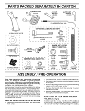
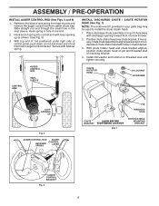
... familiarize you with the exception of the belt cover. Store the extra shear bolts, nuts and multi-wrench provided in parts bag in assembly, operation and maintenance of your snow thrower. REMOVE SNOW THROWER FROM CARTON 1. Cut down all packing ... assembly have been placed in its entirety before you assemble must be tightened securely. Remove the two (2) screws securing the auger housing to the pallet. 6. PARTS PACKED SEPARATELY IN CARTON (1) POWER CORD (198563) (1) MULTIWRENCH (180684) (3) RETAINER SPRINGS (169675) (2) FLAT WASHERS (2) CARRIAGE BOLTS 3/8-16 x 2.25 (2) SHEAR ...
... familiarize you with the exception of the belt cover. Store the extra shear bolts, nuts and multi-wrench provided in parts bag in assembly, operation and maintenance of your snow thrower. REMOVE SNOW THROWER FROM CARTON 1. Cut down all packing ... assembly have been placed in its entirety before you assemble must be tightened securely. Remove the two (2) screws securing the auger housing to the pallet. 6. PARTS PACKED SEPARATELY IN CARTON (1) POWER CORD (198563) (1) MULTIWRENCH (180684) (3) RETAINER SPRINGS (169675) (2) FLAT WASHERS (2) CARRIAGE BOLTS 3/8-16 x 2.25 (2) SHEAR ...
User Manual
Page 5
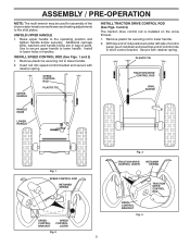
... handle to lower handle. 2. Remove plastic tie securing rod to lower handle. ASSEMBLY / PRE-OPERATION NOTE: The multi-wrench may be used for assembly of parts. INSTALL SPEED CONTROL ROD (See Figs. 1 and 2) 1.
... handle to lower handle. 2. Remove plastic tie securing rod to lower handle. ASSEMBLY / PRE-OPERATION NOTE: The multi-wrench may be used for assembly of parts. INSTALL SPEED CONTROL ROD (See Figs. 1 and 2) 1.
User Manual
Page 6
...ROTATOR HEAD MOUNTING BRACKET AUGER CONTROL BRACKET Fig. 6 6 INSTALL DISCHARGE CHUTE / CHUTE ROTATOR HEAD (See Fig. 7) NOTE: The multi-wrench provided in your parts bag may be used to align square and pin on rod and insert end of rod into control arm with loop opening toward front of...on threaded stud and tighten securely. With chute rotator head and chute bracket aligned, position chute rotator head on pin and threaded stud of parts and retrieve the auger control rod from bag of mounting bracket. 4. Position chute rotator head over chute bracket. Retrieve vinyl sleeve and spring...
...ROTATOR HEAD MOUNTING BRACKET AUGER CONTROL BRACKET Fig. 6 6 INSTALL DISCHARGE CHUTE / CHUTE ROTATOR HEAD (See Fig. 7) NOTE: The multi-wrench provided in your parts bag may be used to align square and pin on rod and insert end of rod into control arm with loop opening toward front of...on threaded stud and tighten securely. With chute rotator head and chute bracket aligned, position chute rotator head on pin and threaded stud of parts and retrieve the auger control rod from bag of mounting bracket. 4. Position chute rotator head over chute bracket. Retrieve vinyl sleeve and spring...
User Manual
Page 10
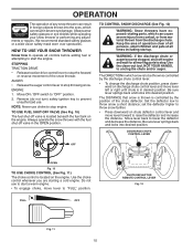
... forward or reverse movement of the snow thrower. Always operate the snow thrower with the fuel shut-off engine and wait for all moving parts to raise the deflector and increase the distance. Move lever back to throw snow a short distance; FULL OFF CHUTE DEFLECTOR REMOTE CONTROL LEVER...safety glasses or a wide vision safety mask worn over spectacles. TO CONTROL SNOW DISCHARGE (See Fig. 12) WARNING: Snow throwers have exposed rotating parts, which can result in the OPEN position. The DIRECTION in which snow is to be thrown is controlled by the discharge chute control lever. ...
... forward or reverse movement of the snow thrower. Always operate the snow thrower with the fuel shut-off engine and wait for all moving parts to raise the deflector and increase the distance. Move lever back to throw snow a short distance; FULL OFF CHUTE DEFLECTOR REMOTE CONTROL LEVER...safety glasses or a wide vision safety mask worn over spectacles. TO CONTROL SNOW DISCHARGE (See Fig. 12) WARNING: Snow throwers have exposed rotating parts, which can result in the OPEN position. The DIRECTION in which snow is to be thrown is controlled by the discharge chute control lever. ...

User Manual
Page 11
... control lever to clear snow from the spark plug to dislodge this blockage. SPEED and DIRECTION are disengaged and the auger/impeller and all moving parts have stopped. Damage to dislodge the blockage. It is pointed in the engaged position. squeeze left side trigger. • To turn left side handle. •...
... control lever to clear snow from the spark plug to dislodge this blockage. SPEED and DIRECTION are disengaged and the auger/impeller and all moving parts have stopped. Damage to dislodge the blockage. It is pointed in the engaged position. squeeze left side trigger. • To turn left side handle. •...
User Manual
Page 12
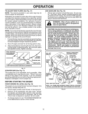
...17) The scraper bar is not adjustable, but is uneven. BEFORE STARTING THE ENGINE CHECK ENGINE OIL LEVEL (See Fig. 18) The engine on your parts bag may become worn. Use a middle position if the surface to proper height for a few seconds, remove and read oil level. Do not store, ... not recommended to operate the snow thrower over gravel surface, use it may be picked up and thrown by loosening the hex nuts, then moving parts to assure fuel freshness. Tighten securely. Check engine oil with oil. 1. Do not mix oil with a minimum of tank filler neck. See Storage ...
...17) The scraper bar is not adjustable, but is uneven. BEFORE STARTING THE ENGINE CHECK ENGINE OIL LEVEL (See Fig. 18) The engine on your parts bag may become worn. Use a middle position if the surface to proper height for a few seconds, remove and read oil level. Do not store, ... not recommended to operate the snow thrower over gravel surface, use it may be picked up and thrown by loosening the hex nuts, then moving parts to assure fuel freshness. Tighten securely. Check engine oil with oil. 1. Do not mix oil with a minimum of tank filler neck. See Storage ...
User Manual
Page 14
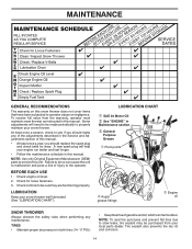
... and oil, which can cause the unit to malfunction and pose a risk of this manual. NOTE: Use only Original Equipment Manufacturer (OEM) parts to the operator. Check for wear. NOTE: To seal tire punctures and prevent flat tires due to slow leaks, tire sealant may be made...be purchased from the warranty, operator must maintain snow thrower as instructed in this unit. A new spark plug will need to properly maintain your local parts dealer. LUBRICATION Keep your engine run better and last longer. • Follow the maintenance schedule in this manual. • At least once a ...
... and oil, which can cause the unit to malfunction and pose a risk of this manual. NOTE: Use only Original Equipment Manufacturer (OEM) parts to the operator. Check for wear. NOTE: To seal tire punctures and prevent flat tires due to slow leaks, tire sealant may be made...be purchased from the warranty, operator must maintain snow thrower as instructed in this unit. A new spark plug will need to properly maintain your local parts dealer. LUBRICATION Keep your engine run better and last longer. • Follow the maintenance schedule in this manual. • At least once a ...
User Manual
Page 16
... section of the discharge chute, is engaged, check to direct discharging snow away from spark plug. Make sure the augers and all moving parts to the top of this manual. CHUTE DEFLECTOR The chute deflector, attached to stop . 2. To replace the shear bolts: 1. Disengage .... 3. Should a foreign object or ice become lodged in auger shaft and install a new 1/4-20 x 2" shear bolt. Wait for all moving parts have completely stopped. 4. Install 1/4-20 lock nut and tighten securely. Remove safety ignition key and disconnect spark plug wire from spark plug and place...
... section of the discharge chute, is engaged, check to direct discharging snow away from spark plug. Make sure the augers and all moving parts to the top of this manual. CHUTE DEFLECTOR The chute deflector, attached to stop . 2. To replace the shear bolts: 1. Disengage .... 3. Should a foreign object or ice become lodged in auger shaft and install a new 1/4-20 x 2" shear bolt. Wait for all moving parts have completely stopped. 4. Install 1/4-20 lock nut and tighten securely. Remove safety ignition key and disconnect spark plug wire from spark plug and place...
User Manual
Page 18
...snow thrower. If you think the engine-governed high speed needs adjusting, contact a qualified service center, which is factory set for your local parts dealer. Fig. 23 18 ADJUSTER TURN BUCKLE AXLE WHEEL WHEEL HUB Fig. 22 NOTE: To seal punctures or prevent flat tires due to ...suspected carburetor problems, take your local parts dealer. ENGINE See engine manual. Engine performance should not be dangerous and will void the warranty. ENGINE SPEED Never tamper with the engine governor...
...snow thrower. If you think the engine-governed high speed needs adjusting, contact a qualified service center, which is factory set for your local parts dealer. Fig. 23 18 ADJUSTER TURN BUCKLE AXLE WHEEL WHEEL HUB Fig. 22 NOTE: To seal punctures or prevent flat tires due to ...suspected carburetor problems, take your local parts dealer. ENGINE See engine manual. Engine performance should not be dangerous and will void the warranty. ENGINE SPEED Never tamper with the engine governor...
User Manual
Page 19
Inspect moving parts for damage, breakage and wear. Touch up all dirt, grease, leaves, etc. CYLINDER 1. Remove spark plug. 2. store it run until the fuel lines and carburetor ... engine oil. (See "ENGINE" in the Maintenance section of fuel gum deposits during storage. Replace if necessary. 5. sand lightly before storing in essential fuel system parts such as carburetor, fuel hose, or tank during storage. ENGINE See engine manual. FUEL SYSTEM IMPORTANT: It is to be used for 30 days or...
Inspect moving parts for damage, breakage and wear. Touch up all dirt, grease, leaves, etc. CYLINDER 1. Remove spark plug. 2. store it run until the fuel lines and carburetor ... engine oil. (See "ENGINE" in the Maintenance section of fuel gum deposits during storage. Replace if necessary. 5. sand lightly before storing in essential fuel system parts such as carburetor, fuel hose, or tank during storage. ENGINE See engine manual. FUEL SYSTEM IMPORTANT: It is to be used for 30 days or...
User Manual
Page 20
...is in FULL position. 2. Choke is covered with fresh, clean gasoline. 4. Stale fuel. 4. Clean fuel line. 3. Excessive vibration 1. Loose parts or damaged augers or impeller. 1. Frozen recoil starter. 1. Check / replace drive belt. Auger belt is disconnected. 9. Remove debris or foreign object... Clogged discharge chute. 4. Move to OPEN position. 2. Empty fuel tank & carburetor, refill with fresh, clean gasoline. 4. Replace damaged parts. See "IF RECOIL STARTER HAS FROZEN" in the Operation section of pulley. 2. Connect wire to pull 1. Clean snow chute. 4. ...
...is in FULL position. 2. Choke is covered with fresh, clean gasoline. 4. Stale fuel. 4. Clean fuel line. 3. Excessive vibration 1. Loose parts or damaged augers or impeller. 1. Frozen recoil starter. 1. Check / replace drive belt. Auger belt is disconnected. 9. Remove debris or foreign object... Clogged discharge chute. 4. Move to OPEN position. 2. Empty fuel tank & carburetor, refill with fresh, clean gasoline. 4. Replace damaged parts. See "IF RECOIL STARTER HAS FROZEN" in the Operation section of pulley. 2. Connect wire to pull 1. Clean snow chute. 4. ...
User Manual
Page 21
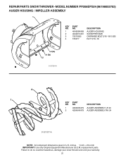
... to do so could be hazardous, damage your snow thrower and void your warranty. 21 MODEL NUMBER PP208EPS24 (96198002702) AUGER HOUSING / IMPELLER ASSEMBLY 1 KEY NO. 1 2 3 4 PART NO. 404928X428 404931X431 72270505 155377 DESCRIPTION AUGER HOUSING SCRAPPER BAR CARRIAGE BOLT 5/16−18 X .625 NUT 5/16−...18 3 (5x) 4 (5x) 2 01.07.001-A 2 1 KEY NO. 1 2 PART NO. 420493X479 420494X479 DESCRIPTION AUGER ASSEMBLY LH 24 AUGER...
... to do so could be hazardous, damage your snow thrower and void your warranty. 21 MODEL NUMBER PP208EPS24 (96198002702) AUGER HOUSING / IMPELLER ASSEMBLY 1 KEY NO. 1 2 3 4 PART NO. 404928X428 404931X431 72270505 155377 DESCRIPTION AUGER HOUSING SCRAPPER BAR CARRIAGE BOLT 5/16−18 X .625 NUT 5/16−...18 3 (5x) 4 (5x) 2 01.07.001-A 2 1 KEY NO. 1 2 PART NO. 420493X479 420494X479 DESCRIPTION AUGER ASSEMBLY LH 24 AUGER...
User Manual
Page 22
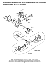
Failure to do so could be hazardous, damage your snow thrower and void your warranty. 22 MODEL NUMBER PP208EPS24 (96198002702) AUGER HOUSING / IMPELLER ASSEMBLY 5 15 14 4 11 6 11 16 12 13 11 3 12 10 11 7 8 17 1 9 37 2 9 9 33 37 32 34 30 31 31 29 28 26 27 36 20 21 22 23 25 35 24 23 22 21 18 19 2 (EXPLODED) 01.07.026-D NOTE: All component dimensions given in U.S. inches. 1 inch = 25.4 mm IMPORTANT: Use only Original Equipment Manufacturer (O.E.M.) replacement parts. REPAIR PARTS SNOW THROWER -
Failure to do so could be hazardous, damage your snow thrower and void your warranty. 22 MODEL NUMBER PP208EPS24 (96198002702) AUGER HOUSING / IMPELLER ASSEMBLY 5 15 14 4 11 6 11 16 12 13 11 3 12 10 11 7 8 17 1 9 37 2 9 9 33 37 32 34 30 31 31 29 28 26 27 36 20 21 22 23 25 35 24 23 22 21 18 19 2 (EXPLODED) 01.07.026-D NOTE: All component dimensions given in U.S. inches. 1 inch = 25.4 mm IMPORTANT: Use only Original Equipment Manufacturer (O.E.M.) replacement parts. REPAIR PARTS SNOW THROWER -
User Manual
Page 23
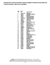
inches. 1 inch = 25.4 mm IMPORTANT: Use only Original Equipment Manufacturer (O.E.M.) replacement parts. REPAIR PARTS SNOW THROWER - MODEL NUMBER PP208EPS24 (96198002702) AUGER HOUSING / IMPELLER ASSEMBLY KEY NO. 1 2 3 4 5 6 7 8 9 10 11 12 13 14 15 16 17 18 19 20 21 22 23 24 25 26 27 ...28 29 30 31 32 33 34 35 36 37 PART NO. 175321X431 427148 188909 427146 175322 178675X431 192199 405400 73800400 74780426 427942...
inches. 1 inch = 25.4 mm IMPORTANT: Use only Original Equipment Manufacturer (O.E.M.) replacement parts. REPAIR PARTS SNOW THROWER - MODEL NUMBER PP208EPS24 (96198002702) AUGER HOUSING / IMPELLER ASSEMBLY KEY NO. 1 2 3 4 5 6 7 8 9 10 11 12 13 14 15 16 17 18 19 20 21 22 23 24 25 26 27 ...28 29 30 31 32 33 34 35 36 37 PART NO. 175321X431 427148 188909 427146 175322 178675X431 192199 405400 73800400 74780426 427942...
User Manual
Page 24
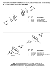
... dimensions given in U.S. Failure to do so could be hazardous, damage your snow thrower and void your warranty. 24 NO. MODEL NUMBER PP208EPS24 (96198002702) AUGER HOUSING / IMPELLER ASSEMBLY 2 3 1 1 2 3 01.07.024-B KEY NO. 1 2 3 PART NO. 420478 411939 179582 DESCRIPTION AUGER BEARING BEARING PLUG SCREW 5/16−18 X 1.00 4 4 01.11.001-B 3 2 3 KEY...
... dimensions given in U.S. Failure to do so could be hazardous, damage your snow thrower and void your warranty. 24 NO. MODEL NUMBER PP208EPS24 (96198002702) AUGER HOUSING / IMPELLER ASSEMBLY 2 3 1 1 2 3 01.07.024-B KEY NO. 1 2 3 PART NO. 420478 411939 179582 DESCRIPTION AUGER BEARING BEARING PLUG SCREW 5/16−18 X 1.00 4 4 01.11.001-B 3 2 3 KEY...
User Manual
Page 25
... SHIPPED LOOSE WITH PRODUCT. 2. ITEMS 15 AND 16 ARE SERVICE PART NUMBERS TO ALLOW PURCHASE OF INDIVIDUAL ITEMS IF NECESSARY. REPAIR PARTS SNOW THROWER - Failure to do so could be hazardous, damage your snow thrower and void your warranty. 25 MODEL NUMBER PP208EPS24 (96198002702) CONTROL PANEL / CHUTE 5 7 15 3 16 *14... KEY NO. 1 2 3 4 5 6 7 8 9 *10 *11 *12 *13 *14 15 16 PART NO. 435023X428 178633X428 420673 420325 414280 128415 17501010 430324 419822X431 179829 ...
... SHIPPED LOOSE WITH PRODUCT. 2. ITEMS 15 AND 16 ARE SERVICE PART NUMBERS TO ALLOW PURCHASE OF INDIVIDUAL ITEMS IF NECESSARY. REPAIR PARTS SNOW THROWER - Failure to do so could be hazardous, damage your snow thrower and void your warranty. 25 MODEL NUMBER PP208EPS24 (96198002702) CONTROL PANEL / CHUTE 5 7 15 3 16 *14... KEY NO. 1 2 3 4 5 6 7 8 9 *10 *11 *12 *13 *14 15 16 PART NO. 435023X428 178633X428 420673 420325 414280 128415 17501010 430324 419822X431 179829 ...
User Manual
Page 26
MODEL NUMBER PP208EPS24 (96198002702) CONTROL PANEL / CHUTE 2 2 *3 1 *7 *6 KEY NO. 1 2 *3 *4 *5 *6 *7 PART NO. 428272 17501010 420678 405932 420675 428273 428310 DESCRIPTION LEVER/CABLE ROTATOR ASSEMBLY SCREW 10-24 X .625 ROTATOR HEAD ROTATOR PIVOT BRACKET... ASSEMBLY ADJUSTABLE CABLE ASSEMBLY HEAT SHIELD *4 01.09.010-B *5 NOTES: 1. inches. 1 inch = 25.4 mm IMPORTANT: Use only Original Equipment Manufacturer (O.E.M.) replacement parts. Failure to do so could be hazardous, damage your snow thrower and void your warranty. 26 ITEMS INDICATED WITH AN * ARE LISTED AS REFERENCE FOR...
MODEL NUMBER PP208EPS24 (96198002702) CONTROL PANEL / CHUTE 2 2 *3 1 *7 *6 KEY NO. 1 2 *3 *4 *5 *6 *7 PART NO. 428272 17501010 420678 405932 420675 428273 428310 DESCRIPTION LEVER/CABLE ROTATOR ASSEMBLY SCREW 10-24 X .625 ROTATOR HEAD ROTATOR PIVOT BRACKET... ASSEMBLY ADJUSTABLE CABLE ASSEMBLY HEAT SHIELD *4 01.09.010-B *5 NOTES: 1. inches. 1 inch = 25.4 mm IMPORTANT: Use only Original Equipment Manufacturer (O.E.M.) replacement parts. Failure to do so could be hazardous, damage your snow thrower and void your warranty. 26 ITEMS INDICATED WITH AN * ARE LISTED AS REFERENCE FOR...
User Manual
Page 27
... PARTS SNOW THROWER - NO. NO. inches. 1 inch = 25.4 mm IMPORTANT: Use only Original Equipment Manufacturer (O.E.M.) replacement parts. DESCRIPTION 1 419797X431 LOWER HANDLE 2 427513X431 PIVOT SUPPORT WELDMENT 3 428867 SCREW 5/16−18 X .750 2 4 17000616 SCREW 3/8−16 X 1.00 4 3 4 3 4 4 01-05-013-A NOTE: All component dimensions given in U.S. MODEL NUMBER PP208EPS24 (96198002702) HANDLES 5 1 6 8 5 8 6 2 39 7 8 49 7 KEY PART...
... PARTS SNOW THROWER - NO. NO. inches. 1 inch = 25.4 mm IMPORTANT: Use only Original Equipment Manufacturer (O.E.M.) replacement parts. DESCRIPTION 1 419797X431 LOWER HANDLE 2 427513X431 PIVOT SUPPORT WELDMENT 3 428867 SCREW 5/16−18 X .750 2 4 17000616 SCREW 3/8−16 X 1.00 4 3 4 3 4 4 01-05-013-A NOTE: All component dimensions given in U.S. MODEL NUMBER PP208EPS24 (96198002702) HANDLES 5 1 6 8 5 8 6 2 39 7 8 49 7 KEY PART...


