
User Manual
Page 1
MODEL NO. PO15538A 15.5 HP 38 Inch Lawn Tractor For Parts and Service, contact our authorized distributor: call 1-800-849-1297 For Technical Assistance: call 1-800-829-5886 188695 11.13.03 TR PRINTED IN U.S.A.
MODEL NO. PO15538A 15.5 HP 38 Inch Lawn Tractor For Parts and Service, contact our authorized distributor: call 1-800-849-1297 For Technical Assistance: call 1-800-829-5886 188695 11.13.03 TR PRINTED IN U.S.A.
User Manual
Page 2
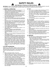
... up to the machine and the mowing activity. Tall grass can hide obstacles. • Grass catcher components are sharp and can cut. mended parts, when necessary. • Use extra care with safe machine operation. • Watch for wheel components and replace with the engine running . Adjust... riding mower safely enough to cool before storage. • Use extra care in speed or direction. • Check brake operation frequently. parts or allow the mower deck to cool before operating or storing the machine. or wear gloves, and use grass catcher on wet grass....
... up to the machine and the mowing activity. Tall grass can hide obstacles. • Grass catcher components are sharp and can cut. mended parts, when necessary. • Use extra care with safe machine operation. • Watch for wheel components and replace with the engine running . Adjust... riding mower safely enough to cool before storage. • Use extra care in speed or direction. • Check brake operation frequently. parts or allow the mower deck to cool before operating or storing the machine. or wear gloves, and use grass catcher on wet grass....

User Manual
Page 4
... 4 ASSEMBLY 6-8 OPERATION 9-13 MAINTENANCE SCHEDULE 14 MAINTENANCE 14-17 SERVICE AND ADJUSTMENTS 18-23 STORAGE 24 TROUBLESHOOTING 25-26 REPAIR PARTS 28-41 WARRANTY 42 4 The instructions will enable you cannot easily remedy, please contact your nearest authorized service center/ department. We...manual. Always observe the "SAFETY RULES". A spark arrester for and using your nearest authorized service center/department (See REPAIR PARTS section of this owner's manual. It has been designed, engineered and manufactured to assemble and maintain your purchase of this ...
... 4 ASSEMBLY 6-8 OPERATION 9-13 MAINTENANCE SCHEDULE 14 MAINTENANCE 14-17 SERVICE AND ADJUSTMENTS 18-23 STORAGE 24 TROUBLESHOOTING 25-26 REPAIR PARTS 28-41 WARRANTY 42 4 The instructions will enable you cannot easily remedy, please contact your nearest authorized service center/ department. We...manual. Always observe the "SAFETY RULES". A spark arrester for and using your nearest authorized service center/department (See REPAIR PARTS section of this owner's manual. It has been designed, engineered and manufactured to assemble and maintain your purchase of this ...
User Manual
Page 5
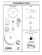
UNASSEMBLED PARTS Steering Wheel Seat Steering Wheel Insert Steering Wheel Adapter Steering Extension Shaft Steering Boot (1) Large Flat Washer (1) Locknut 1/2-20 (1) Hex Bolt 1/4-28 x 1-1/4 (1) Locknut 1/4-28 5 (1) Washer 17/32 x 1-3/16 x 12 Gauge (1) Lock Washer 1/2 (1) Bolt (1) Oil Drain Tube For Future Use Keys (2) Keys Slope Sheet
UNASSEMBLED PARTS Steering Wheel Seat Steering Wheel Insert Steering Wheel Adapter Steering Extension Shaft Steering Boot (1) Large Flat Washer (1) Locknut 1/2-20 (1) Hex Bolt 1/4-28 x 1-1/4 (1) Locknut 1/4-28 5 (1) Washer 17/32 x 1-3/16 x 12 Gauge (1) Lock Washer 1/2 (1) Bolt (1) Oil Drain Tube For Future Use Keys (2) Keys Slope Sheet

User Manual
Page 6
...mentioned in the operating position (seated behind the steering wheel). TO REMOVE TRACTOR FROM CARTON UNPACK CARTON • Remove all accessible loose parts and parts cartons from steering wheel and slide adapter onto steering shaft extension. • Position steering wheel so cross bars are in this manual...extension and lower shafts and install 1/4 hex bolt and locknut. ASSEMBLY Your new tractor has been assembled at the factory with exception of those parts left to right) and slide inside boot and onto adapter. • Assemble large flat washer, 1/2 hex nut and tighten securely....
...mentioned in the operating position (seated behind the steering wheel). TO REMOVE TRACTOR FROM CARTON UNPACK CARTON • Remove all accessible loose parts and parts cartons from steering wheel and slide adapter onto steering shaft extension. • Position steering wheel so cross bars are in this manual...extension and lower shafts and install 1/4 hex bolt and locknut. ASSEMBLY Your new tractor has been assembled at the factory with exception of those parts left to right) and slide inside boot and onto adapter. • Assemble large flat washer, 1/2 hex nut and tighten securely....
User Manual
Page 8
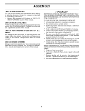
... shown for leveling). ✓ Check mower and drive belts. PLEASE REVIEW THE FOLLOWING CHECKLIST: ✓ All assembly instructions have been completed. ✓ No remaining loose parts in carton. ✓ Battery is properly prepared and charged. (Minimum 1 hour at 6 amps). ✓ Seat is adjusted comfortably and tightened securely. ✓ All tires are...
... shown for leveling). ✓ Check mower and drive belts. PLEASE REVIEW THE FOLLOWING CHECKLIST: ✓ All assembly instructions have been completed. ✓ No remaining loose parts in carton. ✓ Battery is properly prepared and charged. (Minimum 1 hour at 6 amps). ✓ Seat is adjusted comfortably and tightened securely. ✓ All tires are...
User Manual
Page 15
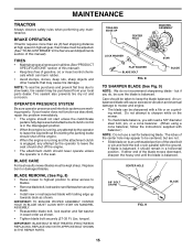
If your local parts dealer. TRAILING EDGE UP CENTER HOLE MANDREL ASSEMBLY LOCK WASHER STAR FLAT WASHER BLADE BOLT FIG. 8 BLADE TO SHARPEN BLADE (See Fig. 9) NOTE: We do , ... the engine is running and the attachment clutch is engaged, any maintenance. IF BOLT NEEDS REPLACING, REPLACE ONLY WITH APPROVE BOLT SHOWN IN THE REPAIR PARTS. OPERATOR PRESENCE SYSTEM Be sure operator presence and interlock systems are not. • Slide blade on a grinding wheel. An unbalanced blade will need a 5/8" diameter steel...
If your local parts dealer. TRAILING EDGE UP CENTER HOLE MANDREL ASSEMBLY LOCK WASHER STAR FLAT WASHER BLADE BOLT FIG. 8 BLADE TO SHARPEN BLADE (See Fig. 9) NOTE: We do , ... the engine is running and the attachment clutch is engaged, any maintenance. IF BOLT NEEDS REPLACING, REPLACE ONLY WITH APPROVE BOLT SHOWN IN THE REPAIR PARTS. OPERATOR PRESENCE SYSTEM Be sure operator presence and interlock systems are not. • Slide blade on a grinding wheel. An unbalanced blade will need a 5/8" diameter steel...
User Manual
Page 18
... (N) position. • Place attachment clutch in "DISENGAGED" position. • Turn ignition key to "STOP" and remove key. • Make sure the blades and all moving parts have completely stopped. • Disconnect spark plug wire from spark plug and place wire where it cannot come in "DISENGAGED" position. • Move attachment lift...
... (N) position. • Place attachment clutch in "DISENGAGED" position. • Turn ignition key to "STOP" and remove key. • Make sure the blades and all moving parts have completely stopped. • Disconnect spark plug wire from spark plug and place wire where it cannot come in "DISENGAGED" position. • Move attachment lift...

User Manual
Page 21
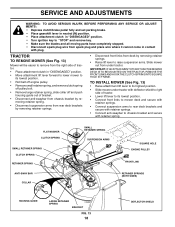
... TO START OTHER VEHICLES. ENGINE PULLEY CLUTCHING IDLER STATIONARY IDLER FRONT WHEEL TOE-IN/CAMBER The front wheel toe-in or camber, contact your local parts dealer. Do not lose). • Repair tire and reassemble. • On rear wheels only: align grooves in axle groove. • Replace axle cover. Insert square...
... TO START OTHER VEHICLES. ENGINE PULLEY CLUTCHING IDLER STATIONARY IDLER FRONT WHEEL TOE-IN/CAMBER The front wheel toe-in or camber, contact your local parts dealer. Do not lose). • Repair tire and reassemble. • On rear wheels only: align grooves in axle groove. • Replace axle cover. Insert square...

User Manual
Page 22
...; Disconnect BLACK battery cable first then RED battery cable and carefully remove battery from tractor. • Install new battery with terminals in the Repair Parts section. SEAT PAN 02602 FIG. 23 22 SERVICE AND ADJUSTMENTS TO REMOVE CABLES, REVERSE ORDER • BLACK cable first from chassis and then from...
...; Disconnect BLACK battery cable first then RED battery cable and carefully remove battery from tractor. • Install new battery with terminals in the Repair Parts section. SEAT PAN 02602 FIG. 23 22 SERVICE AND ADJUSTMENTS TO REMOVE CABLES, REVERSE ORDER • BLACK cable first from chassis and then from...

User Manual
Page 24
...surfaces. CYLINDER(S) • Remove spark plug(s). • Pour one season to another. • Replace your gasoline can if your can starts to rust. Inspect moving parts for winter storage. ENGINE FUEL SYSTEM IMPORTANT: IT IS IMPORTANT TO PREVENT GUM DEPOSITS FROM FORMING IN ESSENTIAL FUEL SYSTEM... PARTS SUCH AS CARBURETOR, FUEL FILTER, FUEL HOSE, OR TANK DURING STORAGE. IMPORTANT: NEVER COVERTRACTORWHILE ENGINE AND EXHAUST AREAS ARE STILL WARM. 24 Do not ...
...surfaces. CYLINDER(S) • Remove spark plug(s). • Pour one season to another. • Replace your gasoline can if your can starts to rust. Inspect moving parts for winter storage. ENGINE FUEL SYSTEM IMPORTANT: IT IS IMPORTANT TO PREVENT GUM DEPOSITS FROM FORMING IN ESSENTIAL FUEL SYSTEM... PARTS SUCH AS CARBURETOR, FUEL FILTER, FUEL HOSE, OR TANK DURING STORAGE. IMPORTANT: NEVER COVERTRACTORWHILE ENGINE AND EXHAUST AREAS ARE STILL WARM. 24 Do not ...

User Manual
Page 25
... or damaged wiring. 4. Low oil level/dirty oil. 6. Engine valves out of adjustment. 10. Worn, bent or loose blade. 2. Loose/damaged part(s). 1. Engine not "CHOKED" properly. 3. Carburetor out of adjustment. 1. Stale or dirty fuel. 6. Disengage attachment clutch. 3. Clean battery terminals. ... 3. Replace blade mandrel. 3. Dirty air filter. 6. Blown fuse. 5. Contact an authorized service center/department. Replace damaged parts. 25 Empty fuel tank and carburetor, refill tank with fresh, clean gasoline. 6. See "To Adjust Carburetor" in fuel....
... or damaged wiring. 4. Low oil level/dirty oil. 6. Engine valves out of adjustment. 10. Worn, bent or loose blade. 2. Loose/damaged part(s). 1. Engine not "CHOKED" properly. 3. Carburetor out of adjustment. 1. Stale or dirty fuel. 6. Disengage attachment clutch. 3. Clean battery terminals. ... 3. Replace blade mandrel. 3. Dirty air filter. 6. Blown fuse. 5. Contact an authorized service center/department. Replace damaged parts. 25 Empty fuel tank and carburetor, refill tank with fresh, clean gasoline. 6. See "To Adjust Carburetor" in fuel....
User Manual
Page 29
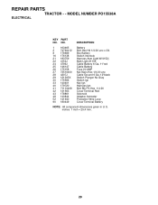
... Red 43 178861 Solenoid 48 140844 Adapter Ammeter 52 141940 Protection Wire Loop 90 180449 Cover Terminal Battery NOTE: All component dimensions given in U. REPAIR PARTS TRACTOR - - S. inches 1 inch = 25.4 mm. 29 MODEL NUMBER PO15538A ELECTRICAL KEY PART NO.
... Red 43 178861 Solenoid 48 140844 Adapter Ammeter 52 141940 Protection Wire Loop 90 180449 Cover Terminal Battery NOTE: All component dimensions given in U. REPAIR PARTS TRACTOR - - S. inches 1 inch = 25.4 mm. 29 MODEL NUMBER PO15538A ELECTRICAL KEY PART NO.
User Manual
Page 31
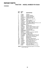
... 34 179717X428 Footrest Pnt RH 35 72110606 Bolt Rdhd Sht Sqnk 3/8-16 x 3/4 37 17490508 Screw Thdrol 5/16-18 x 1/2 TYT 38 175710 Bracket Asm. MODEL NUMBER PO15538A CHASSIS KEY PART NO. REPAIR PARTS TRACTOR - - inches 1 inch = 25.4 mm. 31
... 34 179717X428 Footrest Pnt RH 35 72110606 Bolt Rdhd Sht Sqnk 3/8-16 x 3/4 37 17490508 Screw Thdrol 5/16-18 x 1/2 TYT 38 175710 Bracket Asm. MODEL NUMBER PO15538A CHASSIS KEY PART NO. REPAIR PARTS TRACTOR - - inches 1 inch = 25.4 mm. 31
User Manual
Page 33
... Gr. 5 Washer Lock Hvy Hlcl Spr 7/16 Keeper Belt Engine Guide Belt Mower Drive RH Spacer Axle Washer 25/32 x 1 1/4 x 16 Ga. REPAIR PARTS TRACTOR - - Keeper, Belt Transaxle Bolt Carr Sh 3/8-16 x 1-3/4 Gr. 5 Nut Hex Flg Lock Screw 3/8-16 x 3/4 NOTE: All component dimensions given ... 2 x 10 Ga. Pin Roll 3/16 x 1" Pulley Composite Flat Bolt 3/8-16 x 2-3/4 Keeper Belt Idler Pulley Idler V Groove Plastic KEY PART NO. MODEL NUMBER PO15538A DRIVE KEY PART NO. NO. 1 ------- 2 146682 3 123666X 4 12000028 5 121520X 6 17000512 7 162240 8 131679 10 76020416 11 105701X 12 19151216 13 74550412 ...
... Gr. 5 Washer Lock Hvy Hlcl Spr 7/16 Keeper Belt Engine Guide Belt Mower Drive RH Spacer Axle Washer 25/32 x 1 1/4 x 16 Ga. REPAIR PARTS TRACTOR - - Keeper, Belt Transaxle Bolt Carr Sh 3/8-16 x 1-3/4 Gr. 5 Nut Hex Flg Lock Screw 3/8-16 x 3/4 NOTE: All component dimensions given ... 2 x 10 Ga. Pin Roll 3/16 x 1" Pulley Composite Flat Bolt 3/8-16 x 2-3/4 Keeper Belt Idler Pulley Idler V Groove Plastic KEY PART NO. MODEL NUMBER PO15538A DRIVE KEY PART NO. NO. 1 ------- 2 146682 3 123666X 4 12000028 5 121520X 6 17000512 7 162240 8 131679 10 76020416 11 105701X 12 19151216 13 74550412 ...
User Manual
Page 35
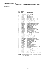
NO. REPAIR PARTS TRACTOR - - inches 1 inch = 25.4 mm. 35 DESCRIPTION 1 140044X428 Wheel Steering 2 175131 Axle Asm 3 169840 Spindle Asm LH 4 169839 Spindle Asm RH 5 6266H Bearing Race Thrust ... 88 175118 Bolt Shoulder 7/16-20 91 175553 Clip Steering 95 188967 Washer Harden .793 x 1.637 x 060 NOTE: All component dimensions given in U.S. MODEL NUMBER PO15538A STEERING KEY PART NO.
NO. REPAIR PARTS TRACTOR - - inches 1 inch = 25.4 mm. 35 DESCRIPTION 1 140044X428 Wheel Steering 2 175131 Axle Asm 3 169840 Spindle Asm LH 4 169839 Spindle Asm RH 5 6266H Bearing Race Thrust ... 88 175118 Bolt Shoulder 7/16-20 91 175553 Clip Steering 95 188967 Washer Harden .793 x 1.637 x 060 NOTE: All component dimensions given in U.S. MODEL NUMBER PO15538A STEERING KEY PART NO.
User Manual
Page 36
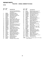
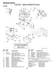
... 1-800-544-2444 1-800-558-5402 1-800-426-7701 1-949-460-5688 36 REPAIR PARTS TRACTOR - - MODEL NUMBER PO15538A ENGINE 2 3 72 1 81 13 4 78 32 44 38 14 78 46 45 33 31 37 23... 33 29 40 KEY PART NO. NO. 1 170551 2 17720408 3 -------- 4 137352 13 165291 14 ...engine-bs.1cyl_49 DESCRIPTION Control Th/ch Flag Screw Hex Thd Cut 1/4-20 x 1/2 Engine, B&S 282H07 (Order parts from engine manufacturer) Muffler Exhaust B&S Gasket Eng 1 313 Id Tin Plated Tube Drain Oil Easy Shield...
... 1-800-544-2444 1-800-558-5402 1-800-426-7701 1-949-460-5688 36 REPAIR PARTS TRACTOR - - MODEL NUMBER PO15538A ENGINE 2 3 72 1 81 13 4 78 32 44 38 14 78 46 45 33 31 37 23... 33 29 40 KEY PART NO. NO. 1 170551 2 17720408 3 -------- 4 137352 13 165291 14 ...engine-bs.1cyl_49 DESCRIPTION Control Th/ch Flag Screw Hex Thd Cut 1/4-20 x 1/2 Engine, B&S 282H07 (Order parts from engine manufacturer) Muffler Exhaust B&S Gasket Eng 1 313 Id Tin Plated Tube Drain Oil Easy Shield...
User Manual
Page 37
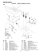
... Washer Lock Hvy Hlcl Spr 1/2 NOTE: All component dimensions given in U.S. MODEL NUMBER PO15538A SEAT 1 8 9 14 7 10 24 26 16 15 5 25 23 8 9 7 2 5 6 22 21 13 17 12 seat_lt.bolt_1 KEY NO. 1 2 3 4 5 6 7 8 9 10 12 13 PART NO. 175389 140551 71110616 19131610 145006 73800600 124181X 17000616 19131614 182493 121246X 121248X DESCRIPTION Seat... 1 x10 Ga. Clip Push-In Hinged Nut Lock Hex w/Ins 3/8 - 16 Spring Seat Cprsn 2 250 Blk Zi Screw 3/8-16 x 1.5 Washer 13/32 x 1 x 14 Ga. REPAIR PARTS TRACTOR - - Pan Pnt Seat (Blk) Bracket Pnt Mounting Switch Bushing Snap Blk Nyl 4 3 KEY...
... Washer Lock Hvy Hlcl Spr 1/2 NOTE: All component dimensions given in U.S. MODEL NUMBER PO15538A SEAT 1 8 9 14 7 10 24 26 16 15 5 25 23 8 9 7 2 5 6 22 21 13 17 12 seat_lt.bolt_1 KEY NO. 1 2 3 4 5 6 7 8 9 10 12 13 PART NO. 175389 140551 71110616 19131610 145006 73800600 124181X 17000616 19131614 182493 121246X 121248X DESCRIPTION Seat... 1 x10 Ga. Clip Push-In Hinged Nut Lock Hex w/Ins 3/8 - 16 Spring Seat Cprsn 2 250 Blk Zi Screw 3/8-16 x 1.5 Washer 13/32 x 1 x 14 Ga. REPAIR PARTS TRACTOR - - Pan Pnt Seat (Blk) Bracket Pnt Mounting Switch Bushing Snap Blk Nyl 4 3 KEY...
User Manual
Page 38
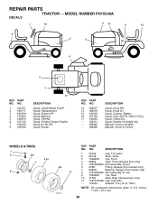
... & TIRES 1 2 5,8 7 6 KEY PART NO. Tube) wheel_1 NOTE: All component dimensions given in U.S. NO. 12 188977 14 188978 15 145005 16 157163 17 136832 - - 138311 - - 188695 - - 188696 DESCRIPTION Decal, Hood RH Decal, Hood LH Decal, Caution, Battery Decal, Oper Sdl P/L Gear Dr Eng Decal, V-Belt Sch. MODEL NUMBER PO15538A DECALS 7 12 2 14... 6 15 9 5 5 16 4 3 KEY PART NO.
... & TIRES 1 2 5,8 7 6 KEY PART NO. Tube) wheel_1 NOTE: All component dimensions given in U.S. NO. 12 188977 14 188978 15 145005 16 157163 17 136832 - - 138311 - - 188695 - - 188696 DESCRIPTION Decal, Hood RH Decal, Hood LH Decal, Caution, Battery Decal, Oper Sdl P/L Gear Dr Eng Decal, V-Belt Sch. MODEL NUMBER PO15538A DECALS 7 12 2 14... 6 15 9 5 5 16 4 3 KEY PART NO.
User Manual
Page 39
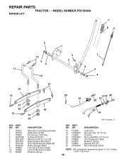
MODEL NUMBER PO15538A MOWER LIFT 7 8 5 13 4 6 11 12 3 2 1 6 5 4 13 19 13 31 32 19 13 31 32 KEY PART NO. inches 1 inch = 25.4 mm. 39 NO. 15 173288 16 73350800 17 175689 18 73800800 19 139868 20 163552 31 169865 32 73540600 ... unc Trunnion Nut Lockw/Wsh 1/2-13 unc Arm Suspension Rear Retainer, Spring Bearing Pvt Lift Nut Crownlock 3/8-24 NOTE: All component dimensions given in U.S. REPAIR PARTS TRACTOR - - NO. 1 159461 2 159476 3 178981 4 12000002 5 19211621 6 120183X 7 109413X 8 124526X 11 139865 12 139866 13 4939M DESCRIPTION Wire Asm Inner/Sprg w/plunger Shaft...
MODEL NUMBER PO15538A MOWER LIFT 7 8 5 13 4 6 11 12 3 2 1 6 5 4 13 19 13 31 32 19 13 31 32 KEY PART NO. inches 1 inch = 25.4 mm. 39 NO. 15 173288 16 73350800 17 175689 18 73800800 19 139868 20 163552 31 169865 32 73540600 ... unc Trunnion Nut Lockw/Wsh 1/2-13 unc Arm Suspension Rear Retainer, Spring Bearing Pvt Lift Nut Crownlock 3/8-24 NOTE: All component dimensions given in U.S. REPAIR PARTS TRACTOR - - NO. 1 159461 2 159476 3 178981 4 12000002 5 19211621 6 120183X 7 109413X 8 124526X 11 139865 12 139866 13 4939M DESCRIPTION Wire Asm Inner/Sprg w/plunger Shaft...


