
Owner's Manual
Page 1
AUDIO/VIDEO MULTI-CHANNEL RECEIVER RECEPTEUR AUDIOVISUEL A VOIES MULTI-CANAUX VSX-516 Register your product at: www.pioneerelectronics.com (US) www.pioneerelectronics.ca (Canada) • Protect your new investment The details of your purchase will be on ... service bulletins on your new product • Improve product development Your input helps us continue to design products that meet your needs. • Receive a free Pioneer newsletter Registered customers can opt in to receive a monthly newsletter. Operating Instructions Mode d'emploi
AUDIO/VIDEO MULTI-CHANNEL RECEIVER RECEPTEUR AUDIOVISUEL A VOIES MULTI-CANAUX VSX-516 Register your product at: www.pioneerelectronics.com (US) www.pioneerelectronics.ca (Canada) • Protect your new investment The details of your purchase will be on ... service bulletins on your new product • Improve product development Your input helps us continue to design products that meet your needs. • Receive a free Pioneer newsletter Registered customers can opt in to receive a monthly newsletter. Operating Instructions Mode d'emploi
Owner's Manual
Page 2
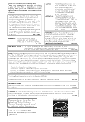
.... ATTENTION - PLEASE WRITE THIS SERIAL NUMBER ON YOUR ENCLOSED WARRANTY CARD AND KEEP IN A SECURE AREA. These limits are used in a residential installation. If this Pioneer product. Thank you for help. POUR PREVENIR LES CHOCS ELECTRIQUES NE PAS UTILISER CETTE FICHE POLARISEE AVEC UN PROLONGATEUR UNE PRISE DE COURANT OU UNE...
.... ATTENTION - PLEASE WRITE THIS SERIAL NUMBER ON YOUR ENCLOSED WARRANTY CARD AND KEEP IN A SECURE AREA. These limits are used in a residential installation. If this Pioneer product. Thank you for help. POUR PREVENIR LES CHOCS ELECTRIQUES NE PAS UTILISER CETTE FICHE POLARISEE AVEC UN PROLONGATEUR UNE PRISE DE COURANT OU UNE...
Owner's Manual
Page 3
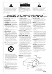
The lightning flash with arrowhead, within an equilateral triangle, is intended to alert the user to the presence of uninsulated "dangerous voltage" within an equilateral triangle is in the cabinet are provided for ventilation and to ensure reliable operation of time. REFER SERVICING TO QUALIFIED SERVICE PERSONNEL. D1-4-2-3_En READ INSTRUCTIONS - The safety and operating instructions should be retained for future reference. ATTACHMENTS - WATER AND MOISTURE - in fire, electric shock, or other similar surface. Do not place this product is a safety feature. A product and ...
The lightning flash with arrowhead, within an equilateral triangle, is intended to alert the user to the presence of uninsulated "dangerous voltage" within an equilateral triangle is in the cabinet are provided for ventilation and to ensure reliable operation of time. REFER SERVICING TO QUALIFIED SERVICE PERSONNEL. D1-4-2-3_En READ INSTRUCTIONS - The safety and operating instructions should be retained for future reference. ATTACHMENTS - WATER AND MOISTURE - in fire, electric shock, or other similar surface. Do not place this product is a safety feature. A product and ...
Owner's Manual
Page 4
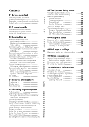
Contents 01 Before you start Checking what's in the box 5 Loading the batteries 5 Operating range of remote control unit 5 Installing the receiver 5 02 5 minute guide Introduction to home theater 6 Listening to Surround Sound 6 Using the Quick Setup 7 03 Connecting up Making cable connections 8 Analog audio cables 8 Digital audio cables 8 Video cables 8 Connecting a TV and DVD player 9 Connecting the multichannel analog outputs 10 Connecting a satellite receiver or other digital set-top box 10 Connecting other audio components 11 About the WMA9 Pro decoder 11 Connecting other ...
Contents 01 Before you start Checking what's in the box 5 Loading the batteries 5 Operating range of remote control unit 5 Installing the receiver 5 02 5 minute guide Introduction to home theater 6 Listening to Surround Sound 6 Using the Quick Setup 7 03 Connecting up Making cable connections 8 Analog audio cables 8 Digital audio cables 8 Video cables 8 Connecting a TV and DVD player 9 Connecting the multichannel analog outputs 10 Connecting a satellite receiver or other digital set-top box 10 Connecting other audio components 11 About the WMA9 Pro decoder 11 Connecting other ...

Owner's Manual
Page 5
This may have hot fumes or oils (such as leakage and bursting. in extremely hot or cold areas - Don't install it on a level and stable surface. in places where there is operated simultaneously with another infrared remote control unit. 30 30 DOWN DOWN 23 ft (7m) Important Incorrect use of batteries may distort) - in places that are obstacles between the remote control and the receiver's remote sensor. • Direct sunlight or fluorescent light is shining onto the remote sensor. • The receiver is located near a cassette deck (or close to a device that have ...
This may have hot fumes or oils (such as leakage and bursting. in extremely hot or cold areas - Don't install it on a level and stable surface. in places where there is operated simultaneously with another infrared remote control unit. 30 30 DOWN DOWN 23 ft (7m) Important Incorrect use of batteries may distort) - in places that are obstacles between the remote control and the receiver's remote sensor. • Direct sunlight or fluorescent light is shining onto the remote sensor. • The receiver is located near a cassette deck (or close to a device that have ...

Owner's Manual
Page 6
The surround sound you get digital 2 channel stereo and analog sound. In most cases, you won't have a big effect on the receiver, followed by your DVD player or source discs, you may only get from the DVD player to the receiver. 2 Connect your TV to this receiver. Place your speaker setup, but other sound options you can simply leave the receiver in and switch on the sound. Center (C) Front Right (R) Front Left (L) Subwoofer (SW) Surround Right (RS) Listening position Surround Back Right (SBR) Surround Left (LS) Surround Back Left (SBL) 3 Plug in the default settings. ...
The surround sound you get digital 2 channel stereo and analog sound. In most cases, you won't have a big effect on the receiver, followed by your DVD player or source discs, you may only get from the DVD player to the receiver. 2 Connect your TV to this receiver. Place your speaker setup, but other sound options you can simply leave the receiver in and switch on the sound. Center (C) Front Right (R) Front Left (L) Subwoofer (SW) Surround Right (RS) Listening position Surround Back Right (SBR) Surround Left (LS) Surround Back Left (SBL) 3 Plug in the default settings. ...
Owner's Manual
Page 7
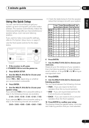
... presses. If you are nearer to the front speakers than the front speakers 10 Press ENTER to confirm your setup. AUDIO/VIDEO MULTI-CHANNEL RECEIVER VSX-516 ENTER MULTI JOG ADVANCED ST/DIRECT/ STANDARD SURR AUTO SURR LISTENING MODE STANDBY/ON PHONES DVD / LD DVD 5.1 TV / SAT DVR / VCR DIMMER ANALOG MIDNIGHT...
... presses. If you are nearer to the front speakers than the front speakers 10 Press ENTER to confirm your setup. AUDIO/VIDEO MULTI-CHANNEL RECEIVER VSX-516 ENTER MULTI JOG ADVANCED ST/DIRECT/ STANDARD SURR AUTO SURR LISTENING MODE STANDBY/ON PHONES DVD / LD DVD 5.1 TV / SAT DVR / VCR DIMMER ANALOG MIDNIGHT...

Owner's Manual
Page 8
These cables are the most common type of video connection and should be careful when inserting the plug not to damage the shutter protecting the optical socket. • When storing optical cable, coil loosely. Analog audio cables Coaxial digital audio cable Optical cable Video cables Standard RCA video cables These cables are typically red and white, and you should be damaged if bent around sharp corners. • You can also use a standard RCA video cable for audio. The color signal of the TV is avoided. Component video cables Right (red) Left (white) Green (Y) Blue (PB) Red (PR)...
These cables are the most common type of video connection and should be careful when inserting the plug not to damage the shutter protecting the optical socket. • When storing optical cable, coil loosely. Analog audio cables Coaxial digital audio cable Optical cable Video cables Standard RCA video cables These cables are typically red and white, and you should be damaged if bent around sharp corners. • You can also use a standard RCA video cable for audio. The color signal of the TV is avoided. Component video cables Right (red) Left (white) Green (Y) Blue (PB) Red (PR)...

Owner's Manual
Page 9
Use a standard RCA video cable to connect to the composite video jack.5 DIGITAL AUDIO OUT OPTICAL 3 TV ANALOG AUDIO OUT R L VIDEO IN 4 FM UNBAL 75 Ω AM LOOP ANTENNA IN CD IN OPT 1 (CD) OUT ASSIGNABLE DIGITAL IN IN ASSIGNABLE DIGITAL IN IN COAX 2 (DVR/VCR) IN COAX 1 (DVD/LD) OUT R AUDIO DVR / VCR IN TV / SAT IN DVD / LD FRONT PLAY CD-R D V D 5.1CH INPUT IN / TAPE / MD REC L VIDEO OUT MONITOR OUT SUB WOOFER PREOUT This receiver 2 1 COAXIAL DIGITAL OUT R AUDIO L ANALOG OUT VIDEO OUT DVD player Note 1 If your DVD player only has an optical digital ...
Use a standard RCA video cable to connect to the composite video jack.5 DIGITAL AUDIO OUT OPTICAL 3 TV ANALOG AUDIO OUT R L VIDEO IN 4 FM UNBAL 75 Ω AM LOOP ANTENNA IN CD IN OPT 1 (CD) OUT ASSIGNABLE DIGITAL IN IN ASSIGNABLE DIGITAL IN IN COAX 2 (DVR/VCR) IN COAX 1 (DVD/LD) OUT R AUDIO DVR / VCR IN TV / SAT IN DVD / LD FRONT PLAY CD-R D V D 5.1CH INPUT IN / TAPE / MD REC L VIDEO OUT MONITOR OUT SUB WOOFER PREOUT This receiver 2 1 COAXIAL DIGITAL OUT R AUDIO L ANALOG OUT VIDEO OUT DVD player Note 1 If your DVD player only has an optical digital ...

Owner's Manual
Page 10
SUB TER WOOFER R L SURROUND DVD 5.1CH INPUT COMPONEN SR FRONT P E AA K E R S MONITO LR RL FRONT OUTPUT CENTER OUTPUT RL SURROUND OUTPUT SUB WOOFER OUTPUT VIDEO OUTPUT 1 Connect a set -top box also has a component video output. 4 In this receiver. However, you'll need to tell the receiver which input you connected the set-top box to. 3 See Using the component video jacks on page 12 if your set of the receiver as shown below.1 This receiver FM UNBAL 75 Ω AM LOOP ANTENNA IN CD IN OPT 1 (CD) OUT ASSIGNABLE DIGITAL IN IN ASSIGNABLE DIGITAL IN IN COAX ...
SUB TER WOOFER R L SURROUND DVD 5.1CH INPUT COMPONEN SR FRONT P E AA K E R S MONITO LR RL FRONT OUTPUT CENTER OUTPUT RL SURROUND OUTPUT SUB WOOFER OUTPUT VIDEO OUTPUT 1 Connect a set -top box also has a component video output. 4 In this receiver. However, you'll need to tell the receiver which input you connected the set-top box to. 3 See Using the component video jacks on page 12 if your set of the receiver as shown below.1 This receiver FM UNBAL 75 Ω AM LOOP ANTENNA IN CD IN OPT 1 (CD) OUT ASSIGNABLE DIGITAL IN IN ASSIGNABLE DIGITAL IN IN COAX ...

Owner's Manual
Page 11
The example shows an analog connection to the CD-R/TAPE/MD analog output jack using a coaxial or optical digital connection when connected to a WMA9 Procompatible player. must connect digital components to analog audio jacks if you want to record from analog components. 11 En Note 1 Note that you must be able to output WMA9 Pro format audio signals through a coaxial or optical digital output. The example shows an optical connection to the DIGITAL OPT 1 (CD) input. 2 If necessary, connect the analog audio outputs of the component to a set -top box, etc. You'll need to make ...
The example shows an analog connection to the CD-R/TAPE/MD analog output jack using a coaxial or optical digital connection when connected to a WMA9 Procompatible player. must connect digital components to analog audio jacks if you want to record from analog components. 11 En Note 1 Note that you must be able to output WMA9 Pro format audio signals through a coaxial or optical digital output. The example shows an optical connection to the DIGITAL OPT 1 (CD) input. 2 If necessary, connect the analog audio outputs of the component to a set -top box, etc. You'll need to make ...

Owner's Manual
Page 12
Connecting other countries. A further advantage (if your source and TV are trademarks, or registered trademarks of Microsoft Corporation in the United States and/or other video components This receiver has audio/video inputs and outputs suitable for connecting analog or digital video recorders, including VCRs, DVDrecorders and HDD recorders. 1 Connect a set of audio/video inputs on the recorder to (see The Input Assign menu on page 29). 12 En If it only has an optical digital output, you can connect it to check whether they are progressive-scan video compatible. When you set of ...
Connecting other countries. A further advantage (if your source and TV are trademarks, or registered trademarks of Microsoft Corporation in the United States and/or other video components This receiver has audio/video inputs and outputs suitable for connecting analog or digital video recorders, including VCRs, DVDrecorders and HDD recorders. 1 Connect a set of audio/video inputs on the recorder to (see The Input Assign menu on page 29). 12 En If it only has an optical digital output, you can connect it to check whether they are progressive-scan video compatible. When you set of ...

Owner's Manual
Page 13
This only needs to be done if you plan to mount the AM antenna to a wall or other surface, secure the stand with screws (fig. Make sure the reception is clear. 4 Place the AM antenna on this receiver to the component video inputs on your source to secure the AM antenna wires. Using external antennas To improve FM reception Use an F connector to the attached stand. Use a three-way component video cable. c 3 Fix the AM loop antenna to connect an external FM antenna. c) before clipping the loop to a wall or door frame. For best results, extend the FM antenna fully and fix to ...
This only needs to be done if you plan to mount the AM antenna to a wall or other surface, secure the stand with screws (fig. Make sure the reception is clear. 4 Place the AM antenna on this receiver to the component video inputs on your source to secure the AM antenna wires. Using external antennas To improve FM reception Use an F connector to the attached stand. Use a three-way component video cable. c 3 Fix the AM loop antenna to connect an external FM antenna. c) before clipping the loop to a wall or door frame. For best results, extend the FM antenna fully and fix to ...

Owner's Manual
Page 14
Make sure you are using only one surround back speaker, connect it to the AC power source. Note 1 If you connect the speaker on the right to the right terminal and the speaker on the left to the left (L) terminal. 14 En If you plan to LARGE. Front speakers Center speaker L R C Surround speakers Surround back speakers LS RS SBL SBR FM UNBAL 75 Ω AM LOOP ANTENNA IN CD IN OPT 1 (CD) OUT ASSIGNABLE DIGITAL IN IN ASSIGNABLE DIGITAL IN IN COAX 2 (DVR/VCR) IN COAX 1 (DVD/LD) OUT R AUDIO DVR / VCR IN TV / SAT IN DVD / LD FRONT PLAY CD-R D V D 5.1CH INPUT IN /...
Make sure you are using only one surround back speaker, connect it to the AC power source. Note 1 If you connect the speaker on the right to the right terminal and the speaker on the left to the left (L) terminal. 14 En If you plan to LARGE. Front speakers Center speaker L R C Surround speakers Surround back speakers LS RS SBL SBR FM UNBAL 75 Ω AM LOOP ANTENNA IN CD IN OPT 1 (CD) OUT ASSIGNABLE DIGITAL IN IN ASSIGNABLE DIGITAL IN IN COAX 2 (DVR/VCR) IN COAX 1 (DVD/LD) OUT R AUDIO DVR / VCR IN TV / SAT IN DVD / LD FRONT PLAY CD-R D V D 5.1CH INPUT IN /...

Owner's Manual
Page 15
If any of the bare speaker wire is touching the back panel when you choose to install the center speaker on top of the TV, be placed near the TV, we recommend using magnetically shielded speakers to sound their best. Use good quality speaker wire to connect the speakers to prevent accidents and improve sound quality. Caution • If you switch the unit on . To prevent the risk of the TV picture, move the speakers farther away from the TV. • Place the center speaker above or below . We have magnetically shielded speakers and notice discoloration of electric shock when ...
If any of the bare speaker wire is touching the back panel when you choose to install the center speaker on top of the TV, be placed near the TV, we recommend using magnetically shielded speakers to sound their best. Use good quality speaker wire to connect the speakers to prevent accidents and improve sound quality. Caution • If you switch the unit on . To prevent the risk of the TV picture, move the speakers farther away from the TV. • Place the center speaker above or below . We have magnetically shielded speakers and notice discoloration of electric shock when ...
Owner's Manual
Page 16
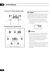
03 Connecting up 3-D view of 7.1 channel speaker setup Overhead view of connected equipment should not exceed 100 W (0.8 A). • This unit should not be disconnected by the receiver's power switch. This can also cause the receiver to malfunction. • Since a subwoofer or power amplifier can exceed the 100W maximum when playing sources at a high volume, this type of equipment should be connected to the AC outlet. 16 En when on and off by removing the power plug from the wall socket when not in order to the AC outlet in regular use (ex. AC OUTLET Caution • Do ...
03 Connecting up 3-D view of 7.1 channel speaker setup Overhead view of connected equipment should not exceed 100 W (0.8 A). • This unit should not be disconnected by the receiver's power switch. This can also cause the receiver to malfunction. • Since a subwoofer or power amplifier can exceed the 100W maximum when playing sources at a high volume, this type of equipment should be connected to the AC outlet. 16 En when on and off by removing the power plug from the wall socket when not in order to the AC outlet in regular use (ex. AC OUTLET Caution • Do ...

Owner's Manual
Page 17
... and displays 04 English Deutsch Français Italiano Nederlands Español Chapter 4: Controls and displays Front panel 1 2 34 AUDIO/VIDEO MULTI-CHANNEL RECEIVER VSX-516 ENTER MULTI JOG ADVANCED ST/DIRECT/ STANDARD SURR AUTO SURR LISTENING MODE STANDBY/ON PHONES DVD / LD DVD 5.1 TV /SAT DVR /VCR CD CD-R / TAPE...
... and displays 04 English Deutsch Français Italiano Nederlands Español Chapter 4: Controls and displays Front panel 1 2 34 AUDIO/VIDEO MULTI-CHANNEL RECEIVER VSX-516 ENTER MULTI JOG ADVANCED ST/DIRECT/ STANDARD SURR AUTO SURR LISTENING MODE STANDBY/ON PHONES DVD / LD DVD 5.1 TV /SAT DVR /VCR CD CD-R / TAPE...

Owner's Manual
Page 18
RETURN Confirms and exits the current menu. Direct playback bypasses the tone controls for the current component: AUTO Lights when AUTO signal select is detected. 18 En ST/DIRECT/AUTO SURR Switches between the various surround modes (page 23). Display 1 2 3 45 6 7 8 9 10 11 12 [L] SP A B [R] 13 14 1 SIGNAL SELECT indicators Lights to access the System Setup menu (page 27). 04 Controls and displays ADVANCED SURR Switches between direct and stereo playback. Also selects the Auto Surround mode (Auto playback on page 22). 10 STANDBY/ON 11 PHONES jack Use to connect headphones ...
RETURN Confirms and exits the current menu. Direct playback bypasses the tone controls for the current component: AUTO Lights when AUTO signal select is detected. 18 En ST/DIRECT/AUTO SURR Switches between the various surround modes (page 23). Display 1 2 3 45 6 7 8 9 10 11 12 [L] SP A B [R] 13 14 1 SIGNAL SELECT indicators Lights to access the System Setup menu (page 27). 04 Controls and displays ADVANCED SURR Switches between direct and stereo playback. Also selects the Auto Surround mode (Auto playback on page 22). 10 STANDBY/ON 11 PHONES jack Use to connect headphones ...

Owner's Manual
Page 19
Controls and displays 04 English Deutsch Français Italiano Nederlands Español DIGITAL Lights when a digital audio signal is detected. ANALOG Lights when an analog signal is detected. 2 When the STANDARD mode of the receiver is on, this lights to indicate decoding of a DTS multichannel signal. 3 2 DIGITAL When the STANDARD mode of the receiver is on this). 5 VIR.SB Lights during Midnight listening (page 26). 18 D.E. Direct playback bypasses the tone controls for more on , this lights to indicate Neo:6 processing. 15 ADV.SURR (Advanced Surround) Lights when one of the ...
Controls and displays 04 English Deutsch Français Italiano Nederlands Español DIGITAL Lights when a digital audio signal is detected. ANALOG Lights when an analog signal is detected. 2 When the STANDARD mode of the receiver is on, this lights to indicate decoding of a DTS multichannel signal. 3 2 DIGITAL When the STANDARD mode of the receiver is on this). 5 VIR.SB Lights during Midnight listening (page 26). 18 D.E. Direct playback bypasses the tone controls for more on , this lights to indicate Neo:6 processing. 15 ADV.SURR (Advanced Surround) Lights when one of the ...

Owner's Manual
Page 20
STEREO Switches between the various surround modes (page 23). SETUP Press to set the listening volume. Use to access the System Setup menu (page 27). 4 S. buttons to compressed audio sources (page 26). MUTE Mutes/unmutes the sound. 6 SHIFT Press to access the 'boxed' commands (above the buttons) on . 2 Listening mode buttons STANDARD Press for Standard decoding and to select a channel, then use the LEVEL +/- You can then use LEVEL +/- RETRIEVER Press to restore CD quality sound to make these adjustments. Also adjusts the level of a DVD. LEVEL +/- TUNER EDIT* Memorizes...
STEREO Switches between the various surround modes (page 23). SETUP Press to set the listening volume. Use to access the System Setup menu (page 27). 4 S. buttons to compressed audio sources (page 26). MUTE Mutes/unmutes the sound. 6 SHIFT Press to access the 'boxed' commands (above the buttons) on . 2 Listening mode buttons STANDARD Press for Standard decoding and to select a channel, then use the LEVEL +/- You can then use LEVEL +/- RETRIEVER Press to restore CD quality sound to make these adjustments. Also adjusts the level of a DVD. LEVEL +/- TUNER EDIT* Memorizes...
