Service Manual
Page 1
... LIST 3 3. PCB PARTS LIST 80 6. Type Model VSX-D906S VSX-07TX VSX-09TX Power Requirement The voltage can be converted by the following method. SAFETY INFORMATION 2 2. PCB CONNECTION DIAGRAM 49 5. Haven 1087, Keetberglaan 1, 9120 Melsele, Belgium PIONEER ELECTRONICS ASIACENTRE PTE. OD PIONEER® The Art of Entertainment Service Manual AUDIONIDEO STEREO RECEIVER VSX-D906S VSX-07TX VSX-09TX ORDER NO.
... LIST 3 3. PCB PARTS LIST 80 6. Type Model VSX-D906S VSX-07TX VSX-09TX Power Requirement The voltage can be converted by the following method. SAFETY INFORMATION 2 2. PCB CONNECTION DIAGRAM 49 5. Haven 1087, Keetberglaan 1, 9120 Melsele, Belgium PIONEER ELECTRONICS ASIACENTRE PTE. OD PIONEER® The Art of Entertainment Service Manual AUDIONIDEO STEREO RECEIVER VSX-D906S VSX-07TX VSX-09TX ORDER NO.
Service Manual
Page 2
... exceed 0.5 mA. Plug the AC line cord of identical designation. on the schematics and on the parts list in the appliance have these special safety characteristics are not... qualified to time. For the latest information, always consult the current PIONEER Service Manual. When servicing or handling circuit boards and other components which have special...above 0.5 mA Test all exposed metal parts of the customer and service technician. VSX-D906S, VSX-07TX, VSX-09TX 1. Device under review and new instructions are identified by the California Health and...
... exceed 0.5 mA. Plug the AC line cord of identical designation. on the schematics and on the parts list in the appliance have these special safety characteristics are not... qualified to time. For the latest information, always consult the current PIONEER Service Manual. When servicing or handling circuit boards and other components which have special...above 0.5 mA Test all exposed metal parts of the customer and service technician. VSX-D906S, VSX-07TX, VSX-09TX 1. Device under review and new instructions are identified by the California Health and...
Service Manual
Page 12
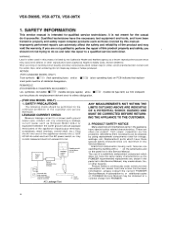
VSX-D906S, VSX-07TX, VSX-09TX 3. ASSY 1` 601, y' .1 D5I ( J13 0156151 JI E VR ASSY o I mw I wJ J10 'N' Dt A"5 EI 150 0_ O EI CURR _9051 I _ DRIVE H1053-1505 ASSY E1 Nrtfy ... DOLBY DIGITAL ASSY 12 FAN 0167012 J11 ," J35 -' 21 4141 { 215009 , ( 015410),, ,„ .52 i 7, 150 i , 909 , iip I 6-1007 (/) CONNECTION ASSY C,657 0T 4 19 1,42 2 OTA 9 t t (' J 0 ..', ,,-. SCHEMATIC DIAGRAM Note : When ordering service parts, be sure to refer to "EXPLODED VIEWS and PARTS LIST" or "PCB PARTS LIST" 3.1 OVERALL CONNECTION DIAGRAM JI7 )15009...
VSX-D906S, VSX-07TX, VSX-09TX 3. ASSY 1` 601, y' .1 D5I ( J13 0156151 JI E VR ASSY o I mw I wJ J10 'N' Dt A"5 EI 150 0_ O EI CURR _9051 I _ DRIVE H1053-1505 ASSY E1 Nrtfy ... DOLBY DIGITAL ASSY 12 FAN 0167012 J11 ," J35 -' 21 4141 { 215009 , ( 015410),, ,„ .52 i 7, 150 i , 909 , iip I 6-1007 (/) CONNECTION ASSY C,657 0T 4 19 1,42 2 OTA 9 t t (' J 0 ..', ,,-. SCHEMATIC DIAGRAM Note : When ordering service parts, be sure to refer to "EXPLODED VIEWS and PARTS LIST" or "PCB PARTS LIST" 3.1 OVERALL CONNECTION DIAGRAM JI7 )15009...
Service Manual
Page 49
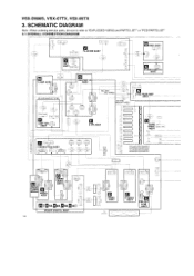
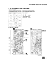
...410 O ----SaeS?t3 ", sass O iu ANP7167-B C 49 Symbol in PCB Diagrams S. 0 0 B C E Symbol in the schematic diagrams. 2. O556 O555 Q558 O554 O557 O559 Q560 O551 O552 O553 044C4J4I 4 LtEle LI uszits tn pot oF. PCB CONNECTION DIAGRAM NOTE...B ; CE 0 (-_, -3,, part Name Transistor 4. VSX-D906S, VSX-07TX, VSX-09TX 4. A companson between the main parts of PCB diagrams Connector / Capacitor SIDE A st' p-t' BC E D G S B C E8 C E Y._ I ( ,-1. ) 143) ''--7-DG SO G S L. Viewpoint of PCB and schematic diagrams is shown below. Part numbers in PCB diagrams ...
...410 O ----SaeS?t3 ", sass O iu ANP7167-B C 49 Symbol in PCB Diagrams S. 0 0 B C E Symbol in the schematic diagrams. 2. O556 O555 Q558 O554 O557 O559 Q560 O551 O552 O553 044C4J4I 4 LtEle LI uszits tn pot oF. PCB CONNECTION DIAGRAM NOTE...B ; CE 0 (-_, -3,, part Name Transistor 4. VSX-D906S, VSX-07TX, VSX-09TX 4. A companson between the main parts of PCB diagrams Connector / Capacitor SIDE A st' p-t' BC E D G S B C E8 C E Y._ I ( ,-1. ) 143) ''--7-DG SO G S L. Viewpoint of PCB and schematic diagrams is shown below. Part numbers in PCB diagrams ...
Service Manual
Page 67
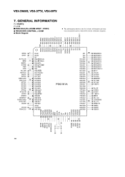
... ►SYSDT ► T.MUTE ► MRCK PCE 164 P LOUDNESS ► CE_210 MRMUTE ►OSDIC ► OSDDT POSDCK STEREO/JOG1 96 rn •=c t2- VSX-D906S, VSX-07TX, VSX-09TX 7. in the schematic diagrams. • Block Diagram >w7- (7) O 0) co h cO u1-1- PE4/RMC PH3/A28 HPIN PE5 PH2/A29 FE_LED 1 1O EEPVCC -41 PE6/PWM PE7...
... ►SYSDT ► T.MUTE ► MRCK PCE 164 P LOUDNESS ► CE_210 MRMUTE ►OSDIC ► OSDDT POSDCK STEREO/JOG1 96 rn •=c t2- VSX-D906S, VSX-07TX, VSX-09TX 7. in the schematic diagrams. • Block Diagram >w7- (7) O 0) co h cO u1-1- PE4/RMC PH3/A28 HPIN PE5 PH2/A29 FE_LED 1 1O EEPVCC -41 PE6/PWM PE7...
