Service Manual
Page 1
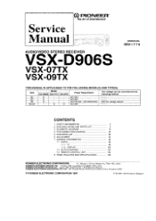
... PARTS LIST 80 6. EXPLODED VIEWS AND PARTS LIST 3 3. SCHEMATIC DIAGRAM 12 4. Haven 1087, Keetberglaan 1, 9120 Melsele, Belgium PIONEER ELECTRONICS ASIACENTRE PTE. RRV 1 7 7 0 THIS MANUAL IS APPLICABLE TO THE FOLLOWING MODEL(S) AND TYPE(S). OD PIONEER® The Art of Entertainment Service Manual AUDIONIDEO STEREO RECEIVER VSX-D906S VSX-07TX VSX-09TX ORDER NO. ADJUSTMENT 93 7. PCB CONNECTION DIAGRAM...
... PARTS LIST 80 6. EXPLODED VIEWS AND PARTS LIST 3 3. SCHEMATIC DIAGRAM 12 4. Haven 1087, Keetberglaan 1, 9120 Melsele, Belgium PIONEER ELECTRONICS ASIACENTRE PTE. RRV 1 7 7 0 THIS MANUAL IS APPLICABLE TO THE FOLLOWING MODEL(S) AND TYPE(S). OD PIONEER® The Art of Entertainment Service Manual AUDIONIDEO STEREO RECEIVER VSX-D906S VSX-07TX VSX-09TX ORDER NO. ADJUSTMENT 93 7. PCB CONNECTION DIAGRAM...
Service Manual
Page 2
...Many electrical and mechanical parts in the appliance have these special safety characteristics are often not evident from PIONEER. 2 on the schematics and on the parts list in this Service Manual. Product Safety is intended for voltage, wattage,...to a known earth ground (water pipe, conduit, etc.) by connecting a leakage current tester such as the PIONEER recommended replacement one, shown in the parts list in this Service Manual, may cause birth defects or other hazards... (input/output terminals, screwheads, metal overlays, control shaft, etc.). VSX-D906S, VSX-07TX, VSX-09TX 1.
...Many electrical and mechanical parts in the appliance have these special safety characteristics are often not evident from PIONEER. 2 on the schematics and on the parts list in this Service Manual. Product Safety is intended for voltage, wattage,...to a known earth ground (water pipe, conduit, etc.) by connecting a leakage current tester such as the PIONEER recommended replacement one, shown in the parts list in this Service Manual, may cause birth defects or other hazards... (input/output terminals, screwheads, metal overlays, control shaft, etc.). VSX-D906S, VSX-07TX, VSX-09TX 1.
Service Manual
Page 12
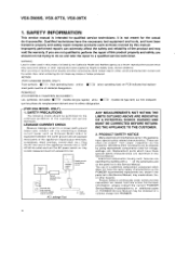
... P LIMITTER Ir/r; J11 ," J35 -' 21 4141 { 215009 , ( 015410),, ,„ .52 i 7, 150 i , 909 , iip I D15A09 750 ) li!2)RMC ASSY ,-4405 ( 215A11 , 221 2'5404 200 9,18. VSX-D906S, VSX-07TX, VSX-09TX 3. SCHEMATIC DIAGRAM Note : When ordering service parts, be sure to refer to "EXPLODED VIEWS and PARTS LIST" or "PCB PARTS LIST" 3.1 OVERALL CONNECTION DIAGRAM JI7...
... P LIMITTER Ir/r; J11 ," J35 -' 21 4141 { 215009 , ( 015410),, ,„ .52 i 7, 150 i , 909 , iip I D15A09 750 ) li!2)RMC ASSY ,-4405 ( 215A11 , 221 2'5404 200 9,18. VSX-D906S, VSX-07TX, VSX-09TX 3. SCHEMATIC DIAGRAM Note : When ordering service parts, be sure to refer to "EXPLODED VIEWS and PARTS LIST" or "PCB PARTS LIST" 3.1 OVERALL CONNECTION DIAGRAM JI7...
Service Manual
Page 49
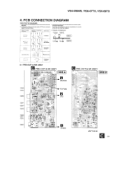
... PRE-OUT & SR ASSY O SIDE B ; Symbol in PCB Diagrams S. 0 0 B C E Symbol in the schematic diagrams. 2. CE 0 (-_, -3,, part Name Transistor 4. a The parts mounted on this PCB include all necessary parts for respecitve destinations. Viewpoint ... ----SaeS?t3 ", sass O iu ANP7167-B C 49 L Transistor with the schematic diagram. Part numbers in PCB diagrams match those in Schematic Diagrams B C EB Ct 0 C, ii ,,-- -1. For further information for several destination. VSX-D906S, VSX-07TX, VSX-09TX 4. A companson between the main parts of PCB diagrams Connector / Capacitor SIDE...
... PRE-OUT & SR ASSY O SIDE B ; Symbol in PCB Diagrams S. 0 0 B C E Symbol in the schematic diagrams. 2. CE 0 (-_, -3,, part Name Transistor 4. a The parts mounted on this PCB include all necessary parts for respecitve destinations. Viewpoint ... ----SaeS?t3 ", sass O iu ANP7167-B C 49 L Transistor with the schematic diagram. Part numbers in PCB diagrams match those in Schematic Diagrams B C EB Ct 0 C, ii ,,-- -1. For further information for several destination. VSX-D906S, VSX-07TX, VSX-09TX 4. A companson between the main parts of PCB diagrams Connector / Capacitor SIDE...
Service Manual
Page 67
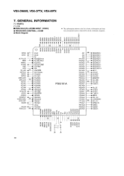
... in the list is basic information and may • RECEIVER CONTROL µ-COM not correspond exactly to that shown in the schematic diagrams. • Block Diagram >w7- (7) O 0) co h cO u1-1- VSX-D906S, VSX-07TX, VSX-09TX 7. CO 0) 0 cD000000O6 ,- -6-i Z.;5' ;,'1- -.-6 GRID2 4 G1/A1 .c.; 5 5 (0 (5 5 A21 GRID1 GO/A0 A22 NC A23 AC PULSE ► PE0/EC0/INTO PI...
... in the list is basic information and may • RECEIVER CONTROL µ-COM not correspond exactly to that shown in the schematic diagrams. • Block Diagram >w7- (7) O 0) co h cO u1-1- VSX-D906S, VSX-07TX, VSX-09TX 7. CO 0) 0 cD000000O6 ,- -6-i Z.;5' ;,'1- -.-6 GRID2 4 G1/A1 .c.; 5 5 (0 (5 5 A21 GRID1 GO/A0 A22 NC A23 AC PULSE ► PE0/EC0/INTO PI...
