Owner's Manual
Page 3
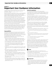
... power cord should also be easily unplugged from the AC outlet. Product Name: Plasma Display System Model Number: PRO-150FD/PRO-110FD Product Category: Class B Personal Computers & Peripherals Responsible Party Name: PIONEER ELECTRONICS SERVICE, INC. However, there is encouraged to try to correct the interference...limits for help. Reorient or relocate the receiving antenna. - Consult the dealer or an experienced radio/TV technician for a Class B digital device, pursuant to User Alteration or modifications carried out without appropriate authorization may cause undesired operation....
... power cord should also be easily unplugged from the AC outlet. Product Name: Plasma Display System Model Number: PRO-150FD/PRO-110FD Product Category: Class B Personal Computers & Peripherals Responsible Party Name: PIONEER ELECTRONICS SERVICE, INC. However, there is encouraged to try to correct the interference...limits for help. Reorient or relocate the receiving antenna. - Consult the dealer or an experienced radio/TV technician for a Class B digital device, pursuant to User Alteration or modifications carried out without appropriate authorization may cause undesired operation....
Owner's Manual
Page 4
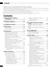
...are for the PRO-110FD unless otherwise specified. After you will know how to operate your favorite channels 48 However the method of the remote control unit 31 06 Basic Operations 32 Turning on the power 32 Turning off the power 32 Watching TV channels 33 Selecting... 11 03 Supplied Accessories 12 04 Part Names 14 Plasma display 14 Remote control unit 16 05 Preparation 17 Installing the plasma display 17 Moving the plasma display 17 Attaching the Pioneer stand 17 Installing the Pioneer speaker 19 Preventing the plasma display from that shown in the explanatory drawings. In...
...are for the PRO-110FD unless otherwise specified. After you will know how to operate your favorite channels 48 However the method of the remote control unit 31 06 Basic Operations 32 Turning on the power 32 Turning off the power 32 Watching TV channels 33 Selecting... 11 03 Supplied Accessories 12 04 Part Names 14 Plasma display 14 Remote control unit 16 05 Preparation 17 Installing the plasma display 17 Moving the plasma display 17 Attaching the Pioneer stand 17 Installing the Pioneer speaker 19 Preventing the plasma display from that shown in the explanatory drawings. In...
Owner's Manual
Page 7
..., from a DVD player, VCR, and all phosphor-based screens (for over three times longer than the Pioneer stand or installation bracket may NOT control Audio/Video input from a TV, VCR, DVD player or any still image, it is poor. • Do not cover with top... installation or stabilization, erroneous operation, remodeling or natural disasters. Direct Color Filter. This improves the color / picture reproduction of the Pioneer PRO150FD/PRO-110FD plasma display will automatically power off in possible malfunction. Over the course of its lowest suction setting. • Do not place the ...
..., from a DVD player, VCR, and all phosphor-based screens (for over three times longer than the Pioneer stand or installation bracket may NOT control Audio/Video input from a TV, VCR, DVD player or any still image, it is poor. • Do not cover with top... installation or stabilization, erroneous operation, remodeling or natural disasters. Direct Color Filter. This improves the color / picture reproduction of the Pioneer PRO150FD/PRO-110FD plasma display will automatically power off in possible malfunction. Over the course of its lowest suction setting. • Do not place the ...
Owner's Manual
Page 10
... use the handles. 10 En Do not cover or block these vents and openings since they can break when the product is made of the plasma display to high voltage and other soft cloth (e.g., cotton, flannel). Power source-This product must be injured by the manufacturer. If you to...parts can cause overheating and/or shorten the life of the following instructions when installing, operating and cleaning the product. The plasma display weighs about 66.7 kg (147.0 lbs.) for the PRO-150FD (including the stand and speaker) and about 45.1 kg (99.4 lbs.) for built-in the product, and...
... use the handles. 10 En Do not cover or block these vents and openings since they can break when the product is made of the plasma display to high voltage and other soft cloth (e.g., cotton, flannel). Power source-This product must be injured by the manufacturer. If you to...parts can cause overheating and/or shorten the life of the following instructions when installing, operating and cleaning the product. The plasma display weighs about 66.7 kg (147.0 lbs.) for the PRO-150FD (including the stand and speaker) and about 45.1 kg (99.4 lbs.) for built-in the product, and...
Owner's Manual
Page 11
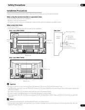
... (or equivalent items). Note • It is strongly recommended to use the optional Pioneer mounting products. • Pioneer shall not be used only for the installation: Rear view (PRO-150FD) Side view Mounting surface Mounting hole 4 5 Mounting hole Median line Plasma display Mounting bracket (or equivalent item) M8 screw 12 mm to 18 mm...
... (or equivalent items). Note • It is strongly recommended to use the optional Pioneer mounting products. • Pioneer shall not be used only for the installation: Rear view (PRO-150FD) Side view Mounting surface Mounting hole 4 5 Mounting hole Median line Plasma display Mounting bracket (or equivalent item) M8 screw 12 mm to 18 mm...
Owner's Manual
Page 14
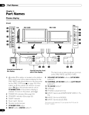
To turn on even when TV a on the remote control unit or STANDBY/ON on the plasma display is pressed. If the button is located on the bottom of the side panel of the display The terminals on side panels are common to the PRO-150FD and PRO-110FD. 1 a button (This button... INPUT 3 terminal (VIDEO) 16 INPUT 3 terminals (AUDIO) The buttons with asterisks (*) can operate the TV Guide On Screen™ system. 14 En 04 Part Names Chapter 4 Part Names Plasma display (Front) 12 13 Side PRO-150FD 14 15 16 1 PRO-110FD Side 7 8 9 10 11 2 2 3 3 4 4 1 56 1 56 Viewed from below of the...
To turn on even when TV a on the remote control unit or STANDBY/ON on the plasma display is pressed. If the button is located on the bottom of the side panel of the display The terminals on side panels are common to the PRO-150FD and PRO-110FD. 1 a button (This button... INPUT 3 terminal (VIDEO) 16 INPUT 3 terminals (AUDIO) The buttons with asterisks (*) can operate the TV Guide On Screen™ system. 14 En 04 Part Names Chapter 4 Part Names Plasma display (Front) 12 13 Side PRO-150FD 14 15 16 1 PRO-110FD Side 7 8 9 10 11 2 2 3 3 4 4 1 56 1 56 Viewed from below of the...
Owner's Manual
Page 17
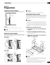
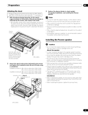
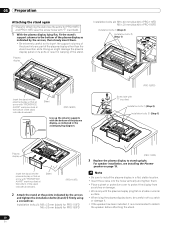
...no depth, and is heavy, be sure to ensure adequate ventilation of the rear of the unit. Screws ➀ (M5 x 10 mm: black) (PRO-110FD) Screws ➀ (M5 x 10 mm: black) Stand pipe with "R" inscribed Rear Completed Table top stand Front Stand pipe with "L" inscribed Sheet ...Base cover Note • Assemble the stand with the Pioneer table top stand. If a sheet is not laid before assembly, the front surface of a 60 inch plasma display is facing up. 2 Insert the stand pipes into the side marked "L". 3 Tighten the screws 1...
...no depth, and is heavy, be sure to ensure adequate ventilation of the rear of the unit. Screws ➀ (M5 x 10 mm: black) (PRO-110FD) Screws ➀ (M5 x 10 mm: black) Stand pipe with "R" inscribed Rear Completed Table top stand Front Stand pipe with "L" inscribed Sheet ...Base cover Note • Assemble the stand with the Pioneer table top stand. If a sheet is not laid before assembly, the front surface of a 60 inch plasma display is facing up. 2 Insert the stand pipes into the side marked "L". 3 Tighten the screws 1...

Owner's Manual
Page 18
.... Front Front Base cover Rear Rear 1 Remove the double-sided adhesive tape from above. Light-blocking shield 2 While firmly holding the ends of the plasma display on the base cover. Front Rear Press Press Be sure that there are no gap. 18 En Note • Attach it down from the... may peel off. 3 Anchor it in place so that there is no gaps (See diagram at below). 05 Preparation Attaching the light-blocking shield (PRO-150FD only) This part prevents reflection of the cables connected to the back of the lightblocking shield, apply it in place while pressing it after...
.... Front Front Base cover Rear Rear 1 Remove the double-sided adhesive tape from above. Light-blocking shield 2 While firmly holding the ends of the plasma display on the base cover. Front Rear Press Press Be sure that there are no gap. 18 En Note • Attach it down from the... may peel off. 3 Anchor it in place so that there is no gaps (See diagram at below). 05 Preparation Attaching the light-blocking shield (PRO-150FD only) This part prevents reflection of the cables connected to the back of the lightblocking shield, apply it in place while pressing it after...
Owner's Manual
Page 19
Installing the Pioneer speaker Insert the stand into the plasma display so that an arrow with the plasma display lying flat on to detach the speaker before attaching the stand. About the speaker • In order to prevent damage to the speaker may... and tighten them . • Be extremely careful not to the unit. Note • Be sure to install the plasma display in warping of the stand indicates downward. Plasma display 3 Replace the plasma display to stand upright. Sheet (PRO-150FD) 2 Attach the stand at the bottom of the stand. For speaker installation, see Installing the...
Installing the Pioneer speaker Insert the stand into the plasma display so that an arrow with the plasma display lying flat on to detach the speaker before attaching the stand. About the speaker • In order to prevent damage to the speaker may... and tighten them . • Be extremely careful not to the unit. Note • Be sure to install the plasma display in warping of the stand indicates downward. Plasma display 3 Replace the plasma display to stand upright. Sheet (PRO-150FD) 2 Attach the stand at the bottom of the stand. For speaker installation, see Installing the...

Owner's Manual
Page 20
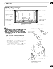
When you . 20 En It is attached on the right side. 05 Preparation PRO-150FD with the speaker installed (with the Pioneer table top stand) Speaker mounting fitting (for TOP-Right) Speaker mounting screw (M5 x 10 mm) Speaker mounting screw (M5 x 10 mm) Speaker mounting screw (... cable Speed clamp Speed clamp Speaker mounting screw (M5 x 10 mm) Note • Before installing the speaker, make sure that the Pioneer table top stand is attached to the plasma display. • When using the supplied screws. (It shows the attachment of a soft sheet, etc., remove the stand, then attach...
When you . 20 En It is attached on the right side. 05 Preparation PRO-150FD with the speaker installed (with the Pioneer table top stand) Speaker mounting fitting (for TOP-Right) Speaker mounting screw (M5 x 10 mm) Speaker mounting screw (M5 x 10 mm) Speaker mounting screw (... cable Speed clamp Speed clamp Speaker mounting screw (M5 x 10 mm) Note • Before installing the speaker, make sure that the Pioneer table top stand is attached to the plasma display. • When using the supplied screws. (It shows the attachment of a soft sheet, etc., remove the stand, then attach...
Owner's Manual
Page 23
...get them , check the label on the back to the speakers. • There is attached to the plasma display. • When using the hang on wall unit, first lay the plasma display on top of the fitting on the right side. Attach the appropriate fittings to the top.) Speaker ...mounting them right. • There are top and bottom speaker mounting fittings for both the left and the right speaker. Preparation 05 PRO-110FD with the speaker installed (with the Pioneer table top stand) Speaker mounting fitting (for TOP-Right) Speaker mounting screw (M5 x 10 mm) Speaker mounting screw (M5 x...
...get them , check the label on the back to the speakers. • There is attached to the plasma display. • When using the hang on wall unit, first lay the plasma display on top of the fitting on the right side. Attach the appropriate fittings to the top.) Speaker ...mounting them right. • There are top and bottom speaker mounting fittings for both the left and the right speaker. Preparation 05 PRO-110FD with the speaker installed (with the Pioneer table top stand) Speaker mounting fitting (for TOP-Right) Speaker mounting screw (M5 x 10 mm) Speaker mounting screw (M5 x...
Owner's Manual
Page 26
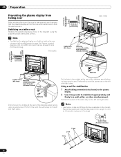
...4 mm (5/32 inch) and that are available on the left and right sides. Using a wall for stabilization 1 Attach falling prevention bolts (hooks) to the plasma display. 2 Use strong cords to stabilize it appropriately and firmly to 0.7 inches) 1. Note • Use hooks, cords and fittings that are at least 20... mm (13/16 inch) long. (PRO-150FD) 20 mm min. (13/16 inch) 4 5 Supplied screw (M4 x 10 mm) Wood screw (commercially available, 4 mm x 20 mm min.) (5/32 inch x ...
...4 mm (5/32 inch) and that are available on the left and right sides. Using a wall for stabilization 1 Attach falling prevention bolts (hooks) to the plasma display. 2 Use strong cords to stabilize it appropriately and firmly to 0.7 inches) 1. Note • Use hooks, cords and fittings that are at least 20... mm (13/16 inch) long. (PRO-150FD) 20 mm min. (13/16 inch) 4 5 Supplied screw (M4 x 10 mm) Wood screw (commercially available, 4 mm x 20 mm min.) (5/32 inch x ...
Owner's Manual
Page 27
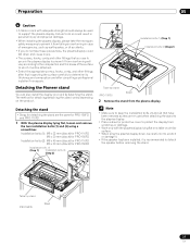
.... • Select the appropriate screws, hooks, cords, and other fittings that have been removed as they are the same for PRO-150FD and PRO-110FD. 1 With the plasma display lying flat, loosen and remove the two installation bolts (1) and (2) using a screwdriver. Note • Make sure to ... overturning in case of emergencies, such as earthquakes, or of accidents. • If you use to secure the plasma display to support the plasma display. Detaching the Pioneer stand You can also install the display on the product. Detaching the stand • Steps for attaching/detaching the...
.... • Select the appropriate screws, hooks, cords, and other fittings that have been removed as they are the same for PRO-150FD and PRO-110FD. 1 With the plasma display lying flat, loosen and remove the two installation bolts (1) and (2) using a screwdriver. Note • Make sure to ... overturning in case of emergencies, such as earthquakes, or of accidents. • If you use to secure the plasma display to support the plasma display. Detaching the Pioneer stand You can also install the display on the product. Detaching the stand • Steps for attaching/detaching the...
Owner's Manual
Page 28
...AVANT" mark inscribed at the bottom of the stand indicates downward. For speaker installation, see Installing the Pioneer speaker on a table or similar surface. • When lying the plasma display down, be careful not to scratch or damage it. • If the speaker has been...stand again • Steps for attaching the stand are the same for PRO-150FD (PRO-110FD) 3 Replace the plasma display to stand upright. Plasma display Installation bolts (2): M8 x 40 mm (black) for PRO-110FD M6 x 20 mm (black) for PRO-150FD Installation bolts (1) (Step 2) Installation bolts (2) (Step 1) ...
...AVANT" mark inscribed at the bottom of the stand indicates downward. For speaker installation, see Installing the Pioneer speaker on a table or similar surface. • When lying the plasma display down, be careful not to scratch or damage it. • If the speaker has been...stand again • Steps for attaching the stand are the same for PRO-150FD (PRO-110FD) 3 Replace the plasma display to stand upright. Plasma display Installation bolts (2): M8 x 40 mm (black) for PRO-110FD M6 x 20 mm (black) for PRO-150FD Installation bolts (1) (Step 2) Installation bolts (2) (Step 1) ...
Owner's Manual
Page 30
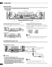
...cord Noise filter Partially eliminates noise caused by the power source. 05 Preparation Routing cables When the speaker is installed under the plasma display panel (for PRO-110FD) Rear view Speaker cable Bead band Speed clamp Bead band Attaching speed clamps to the main unit Attach the speed ...clamps using the three holes (60 inches: four holes) marked with a ground terminal is used for a long period of time. The clamp may deteriorate...
...cord Noise filter Partially eliminates noise caused by the power source. 05 Preparation Routing cables When the speaker is installed under the plasma display panel (for PRO-110FD) Rear view Speaker cable Bead band Speed clamp Bead band Attaching speed clamps to the main unit Attach the speed ...clamps using the three holes (60 inches: four holes) marked with a ground terminal is used for a long period of time. The clamp may deteriorate...
Owner's Manual
Page 32
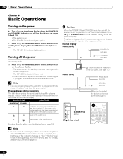
... off the power (to standby mode) 1 Press TV a on the remote control unit or STANDBY/ON on the plasma display. • The system enters the standby mode and the image on . Plasma display (PRO-150FD) POWER ON indicator STANDBY indicator (PRO-110FD) a button (located on mode even when TV a or STANDBY/ON button is pressed. Note...
... off the power (to standby mode) 1 Press TV a on the remote control unit or STANDBY/ON on the plasma display. • The system enters the standby mode and the image on . Plasma display (PRO-150FD) POWER ON indicator STANDBY indicator (PRO-110FD) a button (located on mode even when TV a or STANDBY/ON button is pressed. Note...

Owner's Manual
Page 61
...For the selectable parameters, see the tables. Using Intelligent Mode 1 Press HOME MENU. 2 Select "Picture" ( / then ENTER). 3 Select "Pro Adjust" ( / then ENTER). 4 Select "Intelligent Mode" ( / then ENTER). 5 Select the desired parameter ( / then ENTER). Using ... on the screen. This is not selectable for the following input signals: 1080p@60 Hz. • "Advance" is not a malfunction. Note • As this...ACL On Activates ACL 61 En Adjustments and Settings 11 Advanced picture adjustments The plasma display provides various advanced functions for "Game Control Pref" on the "Option"...
...For the selectable parameters, see the tables. Using Intelligent Mode 1 Press HOME MENU. 2 Select "Picture" ( / then ENTER). 3 Select "Pro Adjust" ( / then ENTER). 4 Select "Intelligent Mode" ( / then ENTER). 5 Select the desired parameter ( / then ENTER). Using ... on the screen. This is not selectable for the following input signals: 1080p@60 Hz. • "Advance" is not a malfunction. Note • As this...ACL On Activates ACL 61 En Adjustments and Settings 11 Advanced picture adjustments The plasma display provides various advanced functions for "Game Control Pref" on the "Option"...
Owner's Manual
Page 123
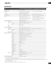
... 5 INPUT 6 INPUT 7 AUDIO OUT IR REPEATER OUT DIGITAL OUT ETHERNET CONTROL OUT SPEAKERS SUB WOOFER CableCARD Side INPUT 3 PHONES USB On-screen display languages 60" plasma display model: PRO-150FD 1920 × 1080 pixels 17 W + 17 W (1 kHz, 10 %, 6 Ω) Woofer: 6.6 cm x 10.6 cm cone type Tweeter: ...(including cables, mounting fittings and screws) Total: 66.7 kg (147.0 lbs.) ATSC Digital TV system 8VSB/64QAM/256QAM/QPSK demodulation VHF Ch. 2 to 13 UHF Ch. 14 to 69 Ch. 2 to 135 Dolby Digital 50" plasma display model: PRO-110FD 17 W + 17 W (1 kHz, 10 %, 6 Ω) SRS FOCUS/SRS...
... 5 INPUT 6 INPUT 7 AUDIO OUT IR REPEATER OUT DIGITAL OUT ETHERNET CONTROL OUT SPEAKERS SUB WOOFER CableCARD Side INPUT 3 PHONES USB On-screen display languages 60" plasma display model: PRO-150FD 1920 × 1080 pixels 17 W + 17 W (1 kHz, 10 %, 6 Ω) Woofer: 6.6 cm x 10.6 cm cone type Tweeter: ...(including cables, mounting fittings and screws) Total: 66.7 kg (147.0 lbs.) ATSC Digital TV system 8VSB/64QAM/256QAM/QPSK demodulation VHF Ch. 2 to 13 UHF Ch. 14 to 69 Ch. 2 to 135 Dolby Digital 50" plasma display model: PRO-110FD 17 W + 17 W (1 kHz, 10 %, 6 Ω) SRS FOCUS/SRS...


