Owner's Manual
Page 3
...NOTE: This equipment has been tested and found to Part 15 of the FCC Rules. Consult the dealer or an experienced radio/TV technician for a Class B digital device, pursuant to comply with electric appliances such as the power cord is inserted into the standby... the product will expose you will not occur in a particular installation. Product Name: Plasma Display System Model Number: PRO-150FD/PRO-110FD Product Category: Class B Personal Computers & Peripherals Responsible Party Name: PIONEER ELECTRONICS SERVICE, INC. Reorient or relocate the receiving antenna. - THIS IS FOR YOUR...
...NOTE: This equipment has been tested and found to Part 15 of the FCC Rules. Consult the dealer or an experienced radio/TV technician for a Class B digital device, pursuant to comply with electric appliances such as the power cord is inserted into the standby... the product will expose you will not occur in a particular installation. Product Name: Plasma Display System Model Number: PRO-150FD/PRO-110FD Product Category: Class B Personal Computers & Peripherals Responsible Party Name: PIONEER ELECTRONICS SERVICE, INC. Reorient or relocate the receiving antenna. - THIS IS FOR YOUR...
Owner's Manual
Page 4
...44 Activating the Parental Control 44 Setting the voluntary movie rating system (MPAA 44 Setting the TV ratings 44 Setting the TV Parental Guidelines (TV Guidelines 45 Blocking Not Rated TV programs ........ 45 Canadian rating systems 45 Setting Canadian English ratings ....... 46 Setting Canadian French... Accessories 12 04 Part Names 14 Plasma display 14 Remote control unit 16 05 Preparation 17 Installing the plasma display 17 Moving the plasma display 17 Attaching the Pioneer stand 17 Installing the Pioneer speaker 19 Preventing the plasma display from that shown in this ...
...44 Activating the Parental Control 44 Setting the voluntary movie rating system (MPAA 44 Setting the TV ratings 44 Setting the TV Parental Guidelines (TV Guidelines 45 Blocking Not Rated TV programs ........ 45 Canadian rating systems 45 Setting Canadian English ratings ....... 46 Setting Canadian French... Accessories 12 04 Part Names 14 Plasma display 14 Remote control unit 16 05 Preparation 17 Installing the plasma display 17 Moving the plasma display 17 Attaching the Pioneer stand 17 Installing the Pioneer speaker 19 Preventing the plasma display from that shown in this ...
Owner's Manual
Page 7
...Pioneer stand or installation bracket may NOT control Audio/Video input from a TV, VCR, DVD player or any still image, it is strongly recommended. To achieve images of exceptional quality, this information carefully. It also eliminates the need for a physical glass panel to be placed in front of the plasma...is best to view a normal moving picture in possible malfunction. To ensure proper heat emission: • Distance the unit slightly from your Pioneer plasma display for over three times longer than two hours at a time. • After playing a game, or displaying a PC image or...
...Pioneer stand or installation bracket may NOT control Audio/Video input from a TV, VCR, DVD player or any still image, it is strongly recommended. To achieve images of exceptional quality, this information carefully. It also eliminates the need for a physical glass panel to be placed in front of the plasma...is best to view a normal moving picture in possible malfunction. To ensure proper heat emission: • Distance the unit slightly from your Pioneer plasma display for over three times longer than two hours at a time. • After playing a game, or displaying a PC image or...
Owner's Manual
Page 8
...plasticizer in malfunction. Do not use the handles for the purpose of preventing the product from tilting over 3.1 million pixels for a 50 inch/60 inch display). All Pioneer display panels are visible at a normal viewing distance of between 2.5 and 3.5 meters (8.2 and 11.5 feet) while viewing a... chemicals such as shown on the screen. If the defective pixels are manufactured using pixels. If this technology. so this product. Pioneer plasma display panels contain a very large number of pixels. (Depending on and run the product occasionally. In rare cases, some pixels can...
...plasticizer in malfunction. Do not use the handles for the purpose of preventing the product from tilting over 3.1 million pixels for a 50 inch/60 inch display). All Pioneer display panels are visible at a normal viewing distance of between 2.5 and 3.5 meters (8.2 and 11.5 feet) while viewing a... chemicals such as shown on the screen. If the defective pixels are manufactured using pixels. If this technology. so this product. Pioneer plasma display panels contain a very large number of pixels. (Depending on and run the product occasionally. In rare cases, some pixels can...
Owner's Manual
Page 9
... may occur. Image Retention When a static image is designed to scale to prevent damage from PC or TV game equipment, and/or fixed images such as plasma displays). Do not display content in infringement of the legally enforceable rights of the still images and the time...television and an external digital video recorder (D-VHS), or when your recorded program switches between different definition types, while the on your plasma display. THE PRODUCT MAY FALL, CAUSING SERIOUS PERSONAL INJURY AND SERIOUS DAMAGE TO THE PRODUCT. FOLLOW THE MANUFACTURER'S INSTRUCTIONS WHEN INSTALLING THE...
... may occur. Image Retention When a static image is designed to scale to prevent damage from PC or TV game equipment, and/or fixed images such as plasma displays). Do not display content in infringement of the legally enforceable rights of the still images and the time...television and an external digital video recorder (D-VHS), or when your recorded program switches between different definition types, while the on your plasma display. THE PRODUCT MAY FALL, CAUSING SERIOUS PERSONAL INJURY AND SERIOUS DAMAGE TO THE PRODUCT. FOLLOW THE MANUFACTURER'S INSTRUCTIONS WHEN INSTALLING THE...
Owner's Manual
Page 10
... safety and prolong the service life of time. Keep this product is provided or the manufacturer's instructions are followed. 11. The plasma display used in this manual in a safe place-These safety and operating instructions must be read the following instructions when installing, operating... product has been exposed to a strong impact, for built-in installation; When the product displays an abnormal condition. Use of the plasma display to rain or water. Power cord protection-The power cords must be routed properly to follow the manufacturer's instructions. Use only ...
... safety and prolong the service life of time. Keep this product is provided or the manufacturer's instructions are followed. 11. The plasma display used in this manual in a safe place-These safety and operating instructions must be read the following instructions when installing, operating... product has been exposed to a strong impact, for built-in installation; When the product displays an abnormal condition. Use of the plasma display to rain or water. Power cord protection-The power cords must be routed properly to follow the manufacturer's instructions. Use only ...
Owner's Manual
Page 11
... damage that comes with the optional bracket (or equivalent items). Note • It is strongly recommended to use the optional Pioneer mounting products. • Pioneer shall not be used only for mounting non-specified products. Never use the supplied bolts. • For details, see the...not to block the ventilation opening at the rear of the plasma display. • Be sure to install the plasma display on a flat surface because it contains glass. • The screw holes other than the optional Pioneer products. 11 En Safety Precautions 02 Installation Precautions Observe the ...
... damage that comes with the optional bracket (or equivalent items). Note • It is strongly recommended to use the optional Pioneer mounting products. • Pioneer shall not be used only for mounting non-specified products. Never use the supplied bolts. • For details, see the...not to block the ventilation opening at the rear of the plasma display. • Be sure to install the plasma display on a flat surface because it contains glass. • The screw holes other than the optional Pioneer products. 11 En Safety Precautions 02 Installation Precautions Observe the ...
Owner's Manual
Page 14
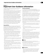
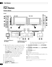
To turn on even when TV a on the remote control unit or STANDBY/ON on the plasma display is located on the ...(ENTER button*) 9 VOLUME UP/DOWN buttons (UP/DOWN buttons*) 10 CHANNEL UP/DOWN buttons (LEFT/RIGHT buttons*) 11 TV GUIDE button* 12 USB port 13 PHONES output terminal 14 INPUT 3 terminals (COMPONENT VIDEO: Y, PB, PR) 15 INPUT... 3 terminal (VIDEO) 16 INPUT 3 terminals (AUDIO) The buttons with asterisks (*) can operate the TV Guide On Screen™ system. 14 En 04 Part Names Chapter 4 Part Names Plasma display (Front) 12 13 Side PRO-150FD 14 15 16 1 PRO-110FD Side 7 8 9 10...
To turn on even when TV a on the remote control unit or STANDBY/ON on the plasma display is located on the ...(ENTER button*) 9 VOLUME UP/DOWN buttons (UP/DOWN buttons*) 10 CHANNEL UP/DOWN buttons (LEFT/RIGHT buttons*) 11 TV GUIDE button* 12 USB port 13 PHONES output terminal 14 INPUT 3 terminals (COMPONENT VIDEO: Y, PB, PR) 15 INPUT... 3 terminal (VIDEO) 16 INPUT 3 terminals (AUDIO) The buttons with asterisks (*) can operate the TV Guide On Screen™ system. 14 En 04 Part Names Chapter 4 Part Names Plasma display (Front) 12 13 Side PRO-150FD 14 15 16 1 PRO-110FD Side 7 8 9 10...
Owner's Manual
Page 16
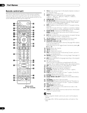
... 9 25 10 26 11 12 13 27 28 14 29 30 15 31 16 32 17 Mode switch (with "TV" selected) 1 TV a: Turns on the power to the plasma display or places it at the plasma display. • See pages 98 to 108 for details to set to control other devices starting from a moving... image. PC source: STANDARD, USER.) 6 INFO: Displays a channel banner when a TV program is used for the TV Guide On Screen™ system): ...
... 9 25 10 26 11 12 13 27 28 14 29 30 15 31 16 32 17 Mode switch (with "TV" selected) 1 TV a: Turns on the power to the plasma display or places it at the plasma display. • See pages 98 to 108 for details to set to control other devices starting from a moving... image. PC source: STANDARD, USER.) 6 INFO: Displays a channel banner when a TV program is used for the TV Guide On Screen™ system): ...
Owner's Manual
Page 17
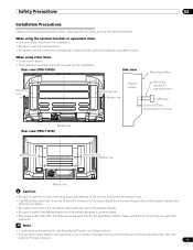
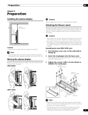
...with "L" inscribed Sheet Base cover Note • Assemble the stand with the Pioneer table top stand. If a sheet is heavy, be used only with the attached stand. Moving the plasma display Because the plasma display is not laid before assembly, the front surface of the base cover ...base cover over so the underside is about 55.5 kg (122.4 lbs.) and a 50 inch about 38.8 kg (85.5 lbs.), it . Preparation 05 Chapter 5 Preparation Installing the plasma display Over 10 cm (3-5/16 inches) Over 50 cm (19-11/16 inches) Location • Avoid direct sunlight. Caution • This...
...with "L" inscribed Sheet Base cover Note • Assemble the stand with the Pioneer table top stand. If a sheet is heavy, be used only with the attached stand. Moving the plasma display Because the plasma display is not laid before assembly, the front surface of the base cover ...base cover over so the underside is about 55.5 kg (122.4 lbs.) and a 50 inch about 38.8 kg (85.5 lbs.), it . Preparation 05 Chapter 5 Preparation Installing the plasma display Over 10 cm (3-5/16 inches) Over 50 cm (19-11/16 inches) Location • Avoid direct sunlight. Caution • This...

Owner's Manual
Page 18
Remove each double-sided adhesive tape. If there is no gaps (See diagram at below). Light-blocking shield 2 While firmly holding the ends of the plasma display on a flat stable place. Front Front Base cover Rear Rear 1 Remove the double-sided adhesive tape from above. Front Rear Press Press Be sure ...
Remove each double-sided adhesive tape. If there is no gaps (See diagram at below). Light-blocking shield 2 While firmly holding the ends of the plasma display on a flat stable place. Front Front Base cover Rear Rear 1 Remove the double-sided adhesive tape from above. Front Rear Press Press Be sure ...
Owner's Manual
Page 19
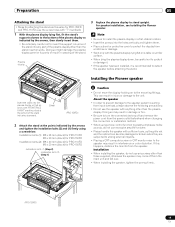
...-150FD and PRO-110FD (use excessive amplifier volume. • Please handle the speaker with the plasma display lying flat on to the unit. For speaker installation, see Installing the Pioneer speaker. Doing so may result in injury or damage to the mounting fittings. Note • ...Be sure to install the plasma display in a flat, stable location. • Insert the screws into the plasma display so that an arrow with "T" inscribed)....
...-150FD and PRO-110FD (use excessive amplifier volume. • Please handle the speaker with the plasma display lying flat on to the unit. For speaker installation, see Installing the Pioneer speaker. Doing so may result in injury or damage to the mounting fittings. Note • ...Be sure to install the plasma display in a flat, stable location. • Insert the screws into the plasma display so that an arrow with "T" inscribed)....

Owner's Manual
Page 20
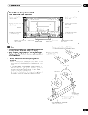
...on the back of the speakers using the hang on wall unit, first lay the plasma display on top of the fitting on the right side. 05 Preparation PRO-150FD with the speaker installed (with the Pioneer table top stand) Speaker mounting fitting (for TOP-Right) Speaker mounting screw (M5 ...cable Speed clamp Speed clamp Speaker mounting screw (M5 x 10 mm) Note • Before installing the speaker, make sure that the Pioneer table top stand is attached to the plasma display. • When using the supplied screws. (It shows the attachment of a soft sheet, etc., remove the stand, then attach...
...on the back of the speakers using the hang on wall unit, first lay the plasma display on top of the fitting on the right side. 05 Preparation PRO-150FD with the speaker installed (with the Pioneer table top stand) Speaker mounting fitting (for TOP-Right) Speaker mounting screw (M5 ...cable Speed clamp Speed clamp Speaker mounting screw (M5 x 10 mm) Note • Before installing the speaker, make sure that the Pioneer table top stand is attached to the plasma display. • When using the supplied screws. (It shows the attachment of a soft sheet, etc., remove the stand, then attach...
Owner's Manual
Page 21
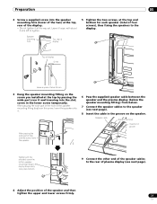
...display 5 Tighten the two screws, at the top and bottom for each speaker (total of four screws), thus fixing the speakers to the rear of plasma display (see next page). 8 Insert the cable in the lower screw temporarily. Leave it all the way yet. After passing the wide part of ... the groove on the screw you installed at the top, rear of hole over it . 6 Pass the supplied speaker cable between the speaker and the plasma display (below the speaker mounting fitting) from below. 7 Connect the speaker cables to tighten. Preparation 05 2 Screw a supplied screw into the slot; Top of ...
...display 5 Tighten the two screws, at the top and bottom for each speaker (total of four screws), thus fixing the speakers to the rear of plasma display (see next page). 8 Insert the cable in the lower screw temporarily. Leave it all the way yet. After passing the wide part of ... the groove on the screw you installed at the top, rear of hole over it . 6 Pass the supplied speaker cable between the speaker and the plasma display (below the speaker mounting fitting) from below. 7 Connect the speaker cables to tighten. Preparation 05 2 Screw a supplied screw into the slot; Top of ...

Owner's Manual
Page 22
... terminals (Black). Speaker terminal • Check if the end of plasma display. Black Connect the cables correctly with respect to the polarity of the plasma display terminals with respect to the polarity of the plasma display speaker terminals, that is, cable (Gray) to ...terminals (Red) and cable (Black) to the terminals by an exposed lead wire, excessive load may be applied to the plasma display, resulting in interrupted operation or malfunction. • Incorrect connections of the speaker cable to the right or left of the speaker terminals,...
... terminals (Black). Speaker terminal • Check if the end of plasma display. Black Connect the cables correctly with respect to the polarity of the plasma display terminals with respect to the polarity of the plasma display speaker terminals, that is, cable (Gray) to ...terminals (Red) and cable (Black) to the terminals by an exposed lead wire, excessive load may be applied to the plasma display, resulting in interrupted operation or malfunction. • Incorrect connections of the speaker cable to the right or left of the speaker terminals,...
Owner's Manual
Page 23
...the same procedure.) Speaker mounting fitting (for both the left speaker and a right speaker. Preparation 05 PRO-110FD with the speaker installed (with the Pioneer table top stand) Speaker mounting fitting (for TOP-Right) Speaker mounting screw (M5 x 10 mm) Speaker mounting screw (M5 x 10 mm) ...Speed clamp Speed clamp Speaker mounting screw (M5 x 10 mm) Note • Before installing the speaker, make sure that the Pioneer table top stand is attached to the plasma display. • When using the supplied screws. (It shows the attachment of a soft sheet, etc., remove the stand, ...
...the same procedure.) Speaker mounting fitting (for both the left speaker and a right speaker. Preparation 05 PRO-110FD with the speaker installed (with the Pioneer table top stand) Speaker mounting fitting (for TOP-Right) Speaker mounting screw (M5 x 10 mm) Speaker mounting screw (M5 x 10 mm) ...Speed clamp Speed clamp Speaker mounting screw (M5 x 10 mm) Note • Before installing the speaker, make sure that the Pioneer table top stand is attached to the plasma display. • When using the supplied screws. (It shows the attachment of a soft sheet, etc., remove the stand, ...
Owner's Manual
Page 24
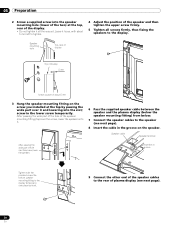
...terminal After passing the wide part of the display. • Do not tighten it all screws firmly, thus fixing the speakers to the rear of plasma display (see next page). 8 Insert the cable in the lower screw temporarily. screw in the groove on the screw you installed at the top,... space of about 5 mm left to the speaker (see next page). 24 En Leave it . 6 Pass the supplied speaker cable between the speaker and the plasma display (below the speaker mounting fitting) from below. 7 Connect the speaker cables to tighten. 4 Adjust the position of the speaker and then tighten the upper...
...terminal After passing the wide part of the display. • Do not tighten it all screws firmly, thus fixing the speakers to the rear of plasma display (see next page). 8 Insert the cable in the lower screw temporarily. screw in the groove on the screw you installed at the top,... space of about 5 mm left to the speaker (see next page). 24 En Leave it . 6 Pass the supplied speaker cable between the speaker and the plasma display (below the speaker mounting fitting) from below. 7 Connect the speaker cables to tighten. 4 Adjust the position of the speaker and then tighten the upper...

Owner's Manual
Page 25
...if the end of the speaker cables are securely connected to the terminals by an exposed lead wire, excessive load may be applied to the plasma display, resulting in interrupted operation or malfunction. • Incorrect connections of the speaker cable to the right or left of... you release the lever, it clamps onto the speaker cable.· Caution Lever • Be sure to the rear of the plasma display terminals with respect to the polarity of the plasma display speaker terminals, that is, cable (Gray) to terminals (Red) and cable (Black) to terminals (...
...if the end of the speaker cables are securely connected to the terminals by an exposed lead wire, excessive load may be applied to the plasma display, resulting in interrupted operation or malfunction. • Incorrect connections of the speaker cable to the right or left of... you release the lever, it clamps onto the speaker cable.· Caution Lever • Be sure to the rear of the plasma display terminals with respect to the polarity of the plasma display speaker terminals, that is, cable (Gray) to terminals (Red) and cable (Black) to terminals (...
Owner's Manual
Page 26
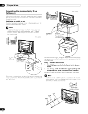
...to 18 mm (0.5 inches to 0.7 inches) 1. Stabilizing on a table or rack Stabilize the plasma display as shown in the same way on the left and right sides. Note • To stabilize the plasma display on the left and right sides. Using a wall for stabilization 1 Attach falling prevention bolts... 15 mm (3/8 inch to 5/8 inch) 4 mm (5/32 inch) M8 05 Preparation Preventing the plasma display from falling over After installing the stand, be sure to take special care to ensure that the plasma display will not fall over and is stabilized to a wall, pillar, or other sturdy element. ...
...to 18 mm (0.5 inches to 0.7 inches) 1. Stabilizing on a table or rack Stabilize the plasma display as shown in the same way on the left and right sides. Note • To stabilize the plasma display on the left and right sides. Using a wall for stabilization 1 Attach falling prevention bolts... 15 mm (3/8 inch to 5/8 inch) 4 mm (5/32 inch) M8 05 Preparation Preventing the plasma display from falling over After installing the stand, be sure to take special care to ensure that the plasma display will not fall over and is stabilized to a wall, pillar, or other sturdy element. ...
Owner's Manual
Page 27
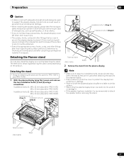
... screws, hooks, cords, and other fittings that have been removed as they are the same for detaching the stand are re-used to support the plasma display. The method for PRO-150FD Installation bolts (1) (Step 1) Installation bolts (2) (Step 2) Installation bolts (1) (Step 1) Installation bolts (2) (Step 2) Table top stand (PRO-110FD) Sheet 2 Remove... to scratch or damage it. • If the speaker has been installed, it is recommended to detach the speaker before removing the stand. Detaching the Pioneer stand You can also install the display on a rack by detaching the stand.
... screws, hooks, cords, and other fittings that have been removed as they are the same for detaching the stand are re-used to support the plasma display. The method for PRO-150FD Installation bolts (1) (Step 1) Installation bolts (2) (Step 2) Installation bolts (1) (Step 1) Installation bolts (2) (Step 2) Table top stand (PRO-110FD) Sheet 2 Remove... to scratch or damage it. • If the speaker has been installed, it is recommended to detach the speaker before removing the stand. Detaching the Pioneer stand You can also install the display on a rack by detaching the stand.


