
Owner's Manual
Page 5
...Contents Contents Safety Precautions i Before Proceeding 2 How to Use This Manual 2 Checking Supplied Accessories 4 Part Names and Functions 5 Main Unit 5 Remote Control Unit 6 Connection Panel 8 Installation and Connections 10 Installation of Terms 55 1 EN Before using your dealer install and set up the ... Display, please read the "Safety Precautions" and these "Operating Instructions" carefully so you very much for purchasing this PIONEER product. PIONEER cannot assume liabilities for Dealers: After installation, be sure to deliver this manual to the customer and explain to the...
...Contents Contents Safety Precautions i Before Proceeding 2 How to Use This Manual 2 Checking Supplied Accessories 4 Part Names and Functions 5 Main Unit 5 Remote Control Unit 6 Connection Panel 8 Installation and Connections 10 Installation of Terms 55 1 EN Before using your dealer install and set up the ... Display, please read the "Safety Precautions" and these "Operating Instructions" carefully so you very much for purchasing this PIONEER product. PIONEER cannot assume liabilities for Dealers: After installation, be sure to deliver this manual to the customer and explain to the...
Owner's Manual
Page 6
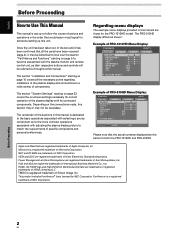
... beneficial to look over the section "Part Names and Functions" starting on page 5 to become acquainted with the plasma monitor and remote control unit, as shown: Example of PRO-1010HD Menu Display: S TA N D A R D PICTURE SCREEN SETUP CONTRAST BRIGHTNESS COLOR TINT SHARPNESS MPEG NR DNR CTI :0...MID : ON PICTURE RESET INPUT1 OPTION SET ENTER MENU EXIT Please note that would seem most logical for both the PRO-1010HD and PRO-810HD. The PRO-810HD display differs as their respective buttons and controls will be necessary. The remainder of the sections in the order that the...
... beneficial to look over the section "Part Names and Functions" starting on page 5 to become acquainted with the plasma monitor and remote control unit, as shown: Example of PRO-1010HD Menu Display: S TA N D A R D PICTURE SCREEN SETUP CONTRAST BRIGHTNESS COLOR TINT SHARPNESS MPEG NR DNR CTI :0...MID : ON PICTURE RESET INPUT1 OPTION SET ENTER MENU EXIT Please note that would seem most logical for both the PRO-1010HD and PRO-810HD. The PRO-810HD display differs as their respective buttons and controls will be necessary. The remainder of the sections in the order that the...
Owner's Manual
Page 7
... proper operating order. Picture and Screen Adjustment Before Proceeding MENU 5/∞ 2/3 SET MENU 2/3 SET 5/∞ AV SELECTION Display operating panel Remote control unit 1 Press the AV SELECTION button to select the desired mode (Refer to page 33). 2 Press the MENU button to the... follows: 3 OFF 2 3 LOW 2 3 HIGH 2 3 MID 2 ¶ As you return to the display shown in practice, depending on the remote control unit, the commands can save picture adjustment setting values for the section "PICTURE adjustment". CTI This lets you press the 2/3 buttons, the setting changes...
... proper operating order. Picture and Screen Adjustment Before Proceeding MENU 5/∞ 2/3 SET MENU 2/3 SET 5/∞ AV SELECTION Display operating panel Remote control unit 1 Press the AV SELECTION button to select the desired mode (Refer to page 33). 2 Press the MENU button to the... follows: 3 OFF 2 3 LOW 2 3 HIGH 2 3 MID 2 ¶ As you return to the display shown in practice, depending on the remote control unit, the commands can save picture adjustment setting values for the section "PICTURE adjustment". CTI This lets you press the 2/3 buttons, the setting changes...

Owner's Manual
Page 8
English Before Proceeding Checking Supplied Accessories Check that the following accessories were supplied. 1 Power cord 2 Remote control unit 3 AA (R6) batteries (x 2) 4 Cleaning cloth (for wiping front panel) 5 Speed clamps (x 2) 6 Bead bands (x 2) ÷ Operating Instructions ÷ Warranty 4 EN Before Proceeding
English Before Proceeding Checking Supplied Accessories Check that the following accessories were supplied. 1 Power cord 2 Remote control unit 3 AA (R6) batteries (x 2) 4 Cleaning cloth (for wiping front panel) 5 Speed clamps (x 2) 6 Bead bands (x 2) ÷ Operating Instructions ÷ Warranty 4 EN Before Proceeding
Owner's Manual
Page 9
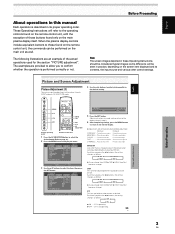
... button Press to select the input (page 29). 7 MENU button Press to open and close the on the main unit PRO-810HD 4 4 5 6 7 8 9 0 = PRO-1010HD 1 23 Main unit 1 Remote control sensor Point the remote control toward the remote sensor to operate the unit (page 7). 2 ON indicator Lights green when the plasma display is in standby mode (page...
... button Press to select the input (page 29). 7 MENU button Press to open and close the on the main unit PRO-810HD 4 4 5 6 7 8 9 0 = PRO-1010HD 1 23 Main unit 1 Remote control sensor Point the remote control toward the remote sensor to operate the unit (page 7). 2 ON indicator Lights green when the plasma display is in standby mode (page...

Owner's Manual
Page 10
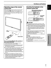
...optimum values (page 39). - STANDBY/ON button Press to put the unit in a place subject to excessive humidity. ¶ When the remote control unit's batteries begin to switch between main screen and subscreen (page 32). ! English Part Names and Functions... Remote Control Unit 1 0 - 2 = 3 4 5 6 7 ~ 8 ! 9 @ AXD1496 When handling the remote control unit ¶ Do not drop the remote control unit or expose it to moisture. ¶ Do not use the remote control unit in a location subject to direct sunlight, heat radiation...
...optimum values (page 39). - STANDBY/ON button Press to put the unit in a place subject to excessive humidity. ¶ When the remote control unit's batteries begin to switch between main screen and subscreen (page 32). ! English Part Names and Functions... Remote Control Unit 1 0 - 2 = 3 4 5 6 7 ~ 8 ! 9 @ AXD1496 When handling the remote control unit ¶ Do not drop the remote control unit or expose it to moisture. ¶ Do not use the remote control unit in a location subject to direct sunlight, heat radiation...
Owner's Manual
Page 11
... from this unit. ¶ Depending on the installation surroundings, this unit may be influenced by the infrared rays discharged from the remote control unit to wear out, replace weak batteries with governmental regulations or environmental public instruction's rules that apply in the battery case....display, hampering reception of its rays or limiting its operational distance. CAUTION ¶ Insert batteries so that component's reception of the remote control's signal, or prevent it from the screen will gradually become shorter as possible. ¶ This unit discharges infrared rays ...
... from this unit. ¶ Depending on the installation surroundings, this unit may be influenced by the infrared rays discharged from the remote control unit to wear out, replace weak batteries with governmental regulations or environmental public instruction's rules that apply in the battery case....display, hampering reception of its rays or limiting its operational distance. CAUTION ¶ Insert batteries so that component's reception of the remote control's signal, or prevent it from the screen will gradually become shorter as possible. ¶ This unit discharges infrared rays ...
Owner's Manual
Page 23
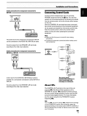
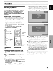
...INPUT1 to INPUT5 of this unit and other PIONEER equipment having the Î logo. Note If you use SR+, be connected to the AUDIO R/L (INPUT5) pin jacks. Face the remote control units to the remote control sensor on your PIONEER AV receiver. When doing this, assign the... appropriate setting on this unit when operating the connected equipment. Sound is output from the remote control units. About SR+ The CONTROL OUT ...
...INPUT1 to INPUT5 of this unit and other PIONEER equipment having the Î logo. Note If you use SR+, be connected to the AUDIO R/L (INPUT5) pin jacks. Face the remote control units to the remote control sensor on your PIONEER AV receiver. When doing this, assign the... appropriate setting on this unit when operating the connected equipment. Sound is output from the remote control units. About SR+ The CONTROL OUT ...

Owner's Manual
Page 26
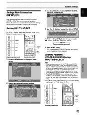
... INPUT1 SELECT SR+ MODE : ENGLISH : STANDARD : OFF : DISABLE : OFF : ON : D-SUB : OFF System Settings MENU 5/∞ STANDBY/ ON 2/3 SET MENU 2/3 SET 5/∞ Display operating panel Remote control unit 1 Set the rear panel MAIN POWER switch to select the desired language. The ON indicator on the front panel will light green. 3 Press...
... INPUT1 SELECT SR+ MODE : ENGLISH : STANDARD : OFF : DISABLE : OFF : ON : D-SUB : OFF System Settings MENU 5/∞ STANDBY/ ON 2/3 SET MENU 2/3 SET 5/∞ Display operating panel Remote control unit 1 Set the rear panel MAIN POWER switch to select the desired language. The ON indicator on the front panel will light green. 3 Press...
Owner's Manual
Page 27
... setting, and returns you want to use D-sub INPUT and HDMI INPUT. MENU 5/∞ 2/3 SET MENU 2/3 SET 5/∞ Display operating panel Remote control unit 1 Press the MENU button to select [INPUT1 SELECT], then press the SET button. S TA N D A R D INPUT1 PICTURE ... below and make settings as follows: 3 D-SUB 2 3 HDMI 2 5 Press the SET button. MENU 5/∞ 2/3 SET Display operating panel MENU 2/3 SET 5/∞ Remote control unit System Settings 23 EN S TA N D A R D PICTURE SCREEN SETUP CONTRAST BRIGHTNESS COLOR TINT SHARPNESS MPEG NR DNR CTI :0 :0 :0 :0 :0 : MID...
... setting, and returns you want to use D-sub INPUT and HDMI INPUT. MENU 5/∞ 2/3 SET MENU 2/3 SET 5/∞ Display operating panel Remote control unit 1 Press the MENU button to select [INPUT1 SELECT], then press the SET button. S TA N D A R D INPUT1 PICTURE ... below and make settings as follows: 3 D-SUB 2 3 HDMI 2 5 Press the SET button. MENU 5/∞ 2/3 SET Display operating panel MENU 2/3 SET 5/∞ Remote control unit System Settings 23 EN S TA N D A R D PICTURE SCREEN SETUP CONTRAST BRIGHTNESS COLOR TINT SHARPNESS MPEG NR DNR CTI :0 :0 :0 :0 :0 : MID...
Owner's Manual
Page 29
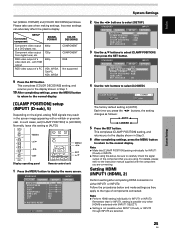
... SCREEN SETUP PURECINEMA : OFF CLAMP POSITION : AUTO SIGNAL FORMAT : 480p COLOR DECODING : RGB HDMI INPUT BRT. MENU 5/∞ 2/3 SET MENU 2/3 SET 5/∞ Display operating panel Remote control unit 1 Press the MENU button to [LOCKED]. Connected component SETUP SIGNAL FORMAT Component video output of components connected.
... SCREEN SETUP PURECINEMA : OFF CLAMP POSITION : AUTO SIGNAL FORMAT : 480p COLOR DECODING : RGB HDMI INPUT BRT. MENU 5/∞ 2/3 SET MENU 2/3 SET 5/∞ Display operating panel Remote control unit 1 Press the MENU button to [LOCKED]. Connected component SETUP SIGNAL FORMAT Component video output of components connected.

Owner's Manual
Page 31
... : ON OPTION System Settings 5 Use the 2/3 buttons to select [AUDIO]. ANALOG: Accept analog audio signals. In this unit to connect another Pioneer product (Refer to page 19 for connection details). 1 Press the MENU button to display the menu screen. This completes [AUDIO] setting, and ... SET S E T HDMI INPUT : AUTO : AUTO MENU E X I T MENU 5/∞ 2/3 SET Display operating panel MENU 2/3 SET 5/∞ Remote control unit SR+MODE setting is selected, automatic switching may not occur properly with the actual signal input. 6 Press the SET button. English AUDIO This...
... : ON OPTION System Settings 5 Use the 2/3 buttons to select [AUDIO]. ANALOG: Accept analog audio signals. In this unit to connect another Pioneer product (Refer to page 19 for connection details). 1 Press the MENU button to display the menu screen. This completes [AUDIO] setting, and ... SET S E T HDMI INPUT : AUTO : AUTO MENU E X I T MENU 5/∞ 2/3 SET Display operating panel MENU 2/3 SET 5/∞ Remote control unit SR+MODE setting is selected, automatic switching may not occur properly with the actual signal input. 6 Press the SET button. English AUDIO This...
Owner's Manual
Page 33
... the plasma display and AV components or personal computer as screen burn which leaves a ghost, or residual, image of the plasma display. Display operating panel Remote control unit VOLUME [+/-] 1 Set the rear panel MAIN POWER switch to INPUT1, INPUT2 and INPUT5 as follows: 3 INPUT1 3 INPUT2 3 INPUT3 INPUT5 2... screen is pressed as described in the operation or standby mode and how to adjust the sound volume. The ON indicator on the remote control unit or the display to select connected components. If no connections are made to these terminals, on the circuitry, and the...
... the plasma display and AV components or personal computer as screen burn which leaves a ghost, or residual, image of the plasma display. Display operating panel Remote control unit VOLUME [+/-] 1 Set the rear panel MAIN POWER switch to INPUT1, INPUT2 and INPUT5 as follows: 3 INPUT1 3 INPUT2 3 INPUT3 INPUT5 2... screen is pressed as described in the operation or standby mode and how to adjust the sound volume. The ON indicator on the remote control unit or the display to select connected components. If no connections are made to these terminals, on the circuitry, and the...

Owner's Manual
Page 34
...width ratios. Although these modes are viewing. Display operating panel Remote control unit Press the DISPLAY button. Changing Screen Size This unit incorporates screen modes of a picture on the remote control unit. Operation Adjusting Sound Volume Confirming Current Status English ...Operation DISPLAY VOLUME [+/-] AXD1496 VOLUME [+/-] DISPLAY Display operating panel Remote control unit Press the VOLUME buttons. Press the [-] or ...
...width ratios. Although these modes are viewing. Display operating panel Remote control unit Press the DISPLAY button. Changing Screen Size This unit incorporates screen modes of a picture on the remote control unit. Operation Adjusting Sound Volume Confirming Current Status English ...Operation DISPLAY VOLUME [+/-] AXD1496 VOLUME [+/-] DISPLAY Display operating panel Remote control unit Press the VOLUME buttons. Press the [-] or ...
Owner's Manual
Page 35
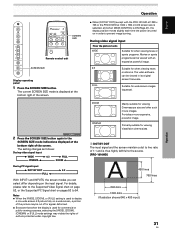
... VistaVision cinema sizes. 1 DOT BY DOT The input signal and the screen maintain a dot to the source. [PRO-1010HD] A 480 lines 768 lines 640 dots 1280 dots (Illustration shows 640 x 480 input.) 31 EN Operation ... for when viewing news or sports programs. Movies or sports programs can be viewed with the PRO-1010HD at 1280 x 768 or the PRO-810HD at the bottom right of the screen. Notes ÷ When the [WIDE], [ZOOM], or...portion of the picture may violate the rights of the screen. SCREEN SIZE Remote control unit SCREEN SIZE Display operating panel 1 Press the SCREEN SIZE button.
... VistaVision cinema sizes. 1 DOT BY DOT The input signal and the screen maintain a dot to the source. [PRO-1010HD] A 480 lines 768 lines 640 dots 1280 dots (Illustration shows 640 x 480 input.) 31 EN Operation ... for when viewing news or sports programs. Movies or sports programs can be viewed with the PRO-1010HD at 1280 x 768 or the PRO-810HD at the bottom right of the screen. Notes ÷ When the [WIDE], [ZOOM], or...portion of the picture may violate the rights of the screen. SCREEN SIZE Remote control unit SCREEN SIZE Display operating panel 1 Press the SCREEN SIZE button.
Owner's Manual
Page 36
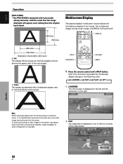
... other than 4:3 whenever possible, unless necessary to avoid infringement of 16:9 and fills the entire screen. A SPLIT SUB INPUT AXD1496 PIP SHIFT SWAP 1 Press the remote control unit's SPLIT button. INPUT1 INPUT2 Note When viewing at aspect ratio 4:3 continuously for numerous hours, or for repeated short periods of time each day... of copyright. 2 PinP The subscreen is presented with the result that the image displayed will appear more oblong than the original input signal. English Operation [PRO-810HD] * The PRO-810HD is displayed on the left and the subscreen on the right.
... other than 4:3 whenever possible, unless necessary to avoid infringement of 16:9 and fills the entire screen. A SPLIT SUB INPUT AXD1496 PIP SHIFT SWAP 1 Press the remote control unit's SPLIT button. INPUT1 INPUT2 Note When viewing at aspect ratio 4:3 continuously for numerous hours, or for repeated short periods of time each day... of copyright. 2 PinP The subscreen is presented with the result that the image displayed will appear more oblong than the original input signal. English Operation [PRO-810HD] * The PRO-810HD is displayed on the left and the subscreen on the right.
Owner's Manual
Page 37
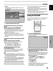
...quality differs. ¶ When performing picture quality adjustment, there are recommended to usually use STANDARD. 33 EN Operation English AXD1496 AV SELECTION Remote control unit 1 Press the AV SELECTION button. Each time you can select between 5 settings during video signal input, and 2 during ...has been selected: The right and left 2 To display the currently selected input: Press the DISPLAY button. INPUT1 INPUT2 2 Press the remote control unit's SUB INPUT button to compress or stretch the image may appear somewhat rougher, depending on for an extended period of the...
...quality differs. ¶ When performing picture quality adjustment, there are recommended to usually use STANDARD. 33 EN Operation English AXD1496 AV SELECTION Remote control unit 1 Press the AV SELECTION button. Each time you can select between 5 settings during video signal input, and 2 during ...has been selected: The right and left 2 To display the currently selected input: Press the DISPLAY button. INPUT1 INPUT2 2 Press the remote control unit's SUB INPUT button to compress or stretch the image may appear somewhat rougher, depending on for an extended period of the...

Owner's Manual
Page 39
...; As you press the 2/3 buttons, the setting changes as desired. Picture and Screen Adjustment MENU 5/∞ 2/3 SET MENU 2/3 SET 5/∞ AV SELECTION Display operating panel Remote control unit 1 Press the AV SELECTION button to select the desired mode (Refer to page 33). 2 Press the MENU button to provide a clearer picture. S TA...
...; As you press the 2/3 buttons, the setting changes as desired. Picture and Screen Adjustment MENU 5/∞ 2/3 SET MENU 2/3 SET 5/∞ AV SELECTION Display operating panel Remote control unit 1 Press the AV SELECTION button to select the desired mode (Refer to page 33). 2 Press the MENU button to provide a clearer picture. S TA...

Owner's Manual
Page 40
..., press the MENU button to return to provide the standard setting. ¶ DRE HIGH...... MENU 5/∞ 2/3 SET MENU 2/3 SET 5/∞ AV SELECTION Display operating panel Remote control unit 1 Press the AV SELECTION button to select the desired mode (Refer to page 33). 2 Press the MENU button to the desired setting. LOW...
..., press the MENU button to return to provide the standard setting. ¶ DRE HIGH...... MENU 5/∞ 2/3 SET MENU 2/3 SET 5/∞ AV SELECTION Display operating panel Remote control unit 1 Press the AV SELECTION button to select the desired mode (Refer to page 33). 2 Press the MENU button to the desired setting. LOW...

Owner's Manual
Page 41
....8 ... HIGH, R. LOW or B. HIGH ... Adjusts the green of dark parts Becomes softer Becomes stronger G. MENU 5/∞ 2/3 SET MENU 2/3 SET 5/∞ AV SELECTION Display operating panel Remote control unit 1 Press the AV SELECTION button to select the desired mode (Refer to page 33). 2 Press the MENU button to MANUAL/ **. ÷ R. 3 LOW 2 3 MID...
....8 ... HIGH, R. LOW or B. HIGH ... Adjusts the green of dark parts Becomes softer Becomes stronger G. MENU 5/∞ 2/3 SET MENU 2/3 SET 5/∞ AV SELECTION Display operating panel Remote control unit 1 Press the AV SELECTION button to select the desired mode (Refer to page 33). 2 Press the MENU button to MANUAL/ **. ÷ R. 3 LOW 2 3 MID...


