
Owner's Manual
Page 2
..., and the point where they exit from tip-over. 13) Unplug this apparatus near any way, such as video-ondemand, a cable operator's enhanced program guide and data-enhanced television services may require the use caution when moving the cart/apparatus combination to view encrypted ...other apparatus (including amplifiers) that produce heat. 9) Do not defeat the safety purpose of receiving analog basic, digital basic and digital premium cable television programming by the manufacturer, or sold with the cart, stand, tripod, bracket, or table specified by direct connection to rain or...
..., and the point where they exit from tip-over. 13) Unplug this apparatus near any way, such as video-ondemand, a cable operator's enhanced program guide and data-enhanced television services may require the use caution when moving the cart/apparatus combination to view encrypted ...other apparatus (including amplifiers) that produce heat. 9) Do not defeat the safety purpose of receiving analog basic, digital basic and digital premium cable television programming by the manufacturer, or sold with the cart, stand, tripod, bracket, or table specified by direct connection to rain or...
Owner's Manual
Page 3
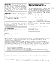
...1_En FEDERAL COMMUNICATIONS COMMISSION DECLARATION OF CONFORMITY This device complies with electric appliances such as radios and televisions, use shielded cables and connectors for connections. Operation is connected. - NOTE: This equipment has been tested and found to operate the ...Name: Plasma Display System (Plasma Display) (Media Receiver) Model Number: PDP-5060HD PDP-4360HD (PDP-506PU) (PDP-436PU) (PDP-R06U) (PDP-R06U) Product Category: Class B Personal Computers & Peripherals Responsible Party Name: PIONEER ELECTRONICS SERVICE, INC. Phone: 310-952-2915 For Business Customer URL ...
...1_En FEDERAL COMMUNICATIONS COMMISSION DECLARATION OF CONFORMITY This device complies with electric appliances such as radios and televisions, use shielded cables and connectors for connections. Operation is connected. - NOTE: This equipment has been tested and found to operate the ...Name: Plasma Display System (Plasma Display) (Media Receiver) Model Number: PDP-5060HD PDP-4360HD (PDP-506PU) (PDP-436PU) (PDP-R06U) (PDP-R06U) Product Category: Class B Personal Computers & Peripherals Responsible Party Name: PIONEER ELECTRONICS SERVICE, INC. Phone: 310-952-2915 For Business Customer URL ...
Owner's Manual
Page 4
... .......21 Preparing the remote control unit 22 Inserting batteries 22 Cautions regarding the remote control unit 22 Connecting the power cord 23 Routing cables 24 09 Tuner Setup Setting up TV channels 38 Using Auto Channel Preset 38 Setting up TV channels manually ....... 38 Checking signal strength...Allowed operation range of the power plug and power outlet may sometimes differ from that shown in a safe place for buying this Pioneer product. Please read through these operating instructions so you will know how to operate your favorite channels 43 Setting up closed captions 43...
... .......21 Preparing the remote control unit 22 Inserting batteries 22 Cautions regarding the remote control unit 22 Connecting the power cord 23 Routing cables 24 09 Tuner Setup Setting up TV channels 38 Using Auto Channel Preset 38 Setting up TV channels manually ....... 38 Checking signal strength...Allowed operation range of the power plug and power outlet may sometimes differ from that shown in a safe place for buying this Pioneer product. Please read through these operating instructions so you will know how to operate your favorite channels 43 Setting up closed captions 43...

Owner's Manual
Page 6
... the learning function 78 Presetting manufacturer codes ...........78 Manufacture codes 79 Using the remote control unit to control other devices 80 Receiver control buttons 80 Cable control buttons 81 SAT control buttons 82 VCR control buttons 83 DVD/DVR control buttons 84 14 Appendix Troubleshooting 85 Specifications 94 6 En
... the learning function 78 Presetting manufacturer codes ...........78 Manufacture codes 79 Using the remote control unit to control other devices 80 Receiver control buttons 80 Cable control buttons 81 SAT control buttons 82 VCR control buttons 83 DVD/DVR control buttons 84 14 Appendix Troubleshooting 85 Specifications 94 6 En
Owner's Manual
Page 11
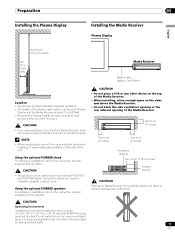
.... 11 En Never use of the Plasma Display. NOTE • It is strongly recommended to use the optional PIONEER mounting products. • PIONEER shall not be used for the installation: Rear view Side view Mounting surface Mounting hole Mounting hole Median line Plasma Display... Mounting bracket (or equivalent item) M8 screw 12 to 18 mm (0.5 to 0.7 inches) SYSTEM CABLE WHITE BLACK Median line CAUTION • Be sure ...
.... 11 En Never use of the Plasma Display. NOTE • It is strongly recommended to use the optional PIONEER mounting products. • PIONEER shall not be used for the installation: Rear view Side view Mounting surface Mounting hole Mounting hole Median line Plasma Display... Mounting bracket (or equivalent item) M8 screw 12 to 18 mm (0.5 to 0.7 inches) SYSTEM CABLE WHITE BLACK Median line CAUTION • Be sure ...
Owner's Manual
Page 12
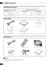
... size battery × 2 (Alkaline battery) G-LINK cable (3 m/9.8 feet) NOTE • Always use the power cord supplied with the Plasma Display and the one supplied with the Media Receiver for each respective unit. 12 En Operating instructions Model Name of the Entire Plasma Display System PDP-5060HD PDP-4360HD The speakers are available as options...
... size battery × 2 (Alkaline battery) G-LINK cable (3 m/9.8 feet) NOTE • Always use the power cord supplied with the Plasma Display and the one supplied with the Media Receiver for each respective unit. 12 En Operating instructions Model Name of the Entire Plasma Display System PDP-5060HD PDP-4360HD The speakers are available as options...
Owner's Manual
Page 13
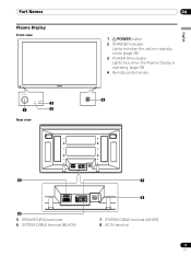
Part Names Part Names Plasma Display Front view 2 1 3 Rear view 04 1 a POWER button 2 STANDBY indicator Lights red when the unit is in standby mode. (page 25) 3 POWER ON indicator Lights blue when the Plasma Display is operating. (page 25) 4 Remote control sensor 4 English 5 SYSTEM CABLE WHITE BLACK SYSTEM CABLE WHITE BLACK 6 5 SPEAKER (R/L) terminals 6 SYSTEM CABLE terminal (BLACK) 7 8 7 SYSTEM CABLE terminal (WHITE) 8 AC IN terminal 13 En
Part Names Part Names Plasma Display Front view 2 1 3 Rear view 04 1 a POWER button 2 STANDBY indicator Lights red when the unit is in standby mode. (page 25) 3 POWER ON indicator Lights blue when the Plasma Display is operating. (page 25) 4 Remote control sensor 4 English 5 SYSTEM CABLE WHITE BLACK SYSTEM CABLE WHITE BLACK 6 5 SPEAKER (R/L) terminals 6 SYSTEM CABLE terminal (BLACK) 7 8 7 SYSTEM CABLE terminal (WHITE) 8 AC IN terminal 13 En

Owner's Manual
Page 15
... SERVICE ONLY R-AUDIO-L VIDEO S-VIDEO INPUT 1 Y CB / PB COMPONENT VIDEO CR / PR INPUT 1 INPUT 3 HDMI BLACK WHITE SYSTEM CABLE AC IN 17 9 10 11 12 13 14 1516 18 19 20 21 1 ANT/CABLE A IN terminal 2 MONITOR OUT terminals (AUDIO) 3 MONITOR OUT terminal (VIDEO) 4 G-LINK terminal 5 i.LINK terminals 6 SUB WOOFER terminal 7 DIGITAL...
... SERVICE ONLY R-AUDIO-L VIDEO S-VIDEO INPUT 1 Y CB / PB COMPONENT VIDEO CR / PR INPUT 1 INPUT 3 HDMI BLACK WHITE SYSTEM CABLE AC IN 17 9 10 11 12 13 14 1516 18 19 20 21 1 ANT/CABLE A IN terminal 2 MONITOR OUT terminals (AUDIO) 3 MONITOR OUT terminal (VIDEO) 4 G-LINK terminal 5 i.LINK terminals 6 SUB WOOFER terminal 7 DIGITAL...
Owner's Manual
Page 17
... %RH (cooling vents not blocked) Do not install this unit in a poorly ventilated area, or in instability, possibly causing injury. Using the optional PIONEER speakers For details on the top of the unit. STANDBY/ON REC ON STANDBY TIMER Over 5 cm (2 inches) PULL OPEN Over 5 cm (2 inches...) Over 5 cm (2 inches) Ventilation opening Over 10 cm (3 15/16 inches) Exhaust opening of the system cable used to the instruction manual supplied with the stand. CAUTION • If you when moving it will not receive enough ventilation and will not operate...
... %RH (cooling vents not blocked) Do not install this unit in a poorly ventilated area, or in instability, possibly causing injury. Using the optional PIONEER speakers For details on the top of the unit. STANDBY/ON REC ON STANDBY TIMER Over 5 cm (2 inches) PULL OPEN Over 5 cm (2 inches...) Over 5 cm (2 inches) Ventilation opening Over 10 cm (3 15/16 inches) Exhaust opening of the system cable used to the instruction manual supplied with the stand. CAUTION • If you when moving it will not receive enough ventilation and will not operate...
Owner's Manual
Page 19
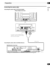
Preparation 05 English Connecting the system cable Connecting the system cable to the Plasma Display Plasma Display (rear view) SYSTEM CABLE WHITE BLACK SYSTEM CABLE WHITE BLACK (BLACK) For details on optional PIONEER speaker installation, refer to the instruction manual that came with the speaker. (WHITE) Connecting the system cable to the Media Receiver Media Receiver (rear...
Preparation 05 English Connecting the system cable Connecting the system cable to the Plasma Display Plasma Display (rear view) SYSTEM CABLE WHITE BLACK SYSTEM CABLE WHITE BLACK (BLACK) For details on optional PIONEER speaker installation, refer to the instruction manual that came with the speaker. (WHITE) Connecting the system cable to the Media Receiver Media Receiver (rear...

Owner's Manual
Page 20
... CONTROL ANT B IN SERVICE ONLY R-AUDIO-L VIDEO S-VIDEO INPUT 1 COM V Connecting VHF/UHF antennas and a Cable VHF antenna UHF antenna U/Vmixer AV cable (commercially available) Cable TV Coaxial ANT B IN ANT/ CABLE A IN Media Receiver (rear) Cable TV Coaxial Cable box NOTE • You can connect that supports digital TV channels and has an RF output...
... CONTROL ANT B IN SERVICE ONLY R-AUDIO-L VIDEO S-VIDEO INPUT 1 COM V Connecting VHF/UHF antennas and a Cable VHF antenna UHF antenna U/Vmixer AV cable (commercially available) Cable TV Coaxial ANT B IN ANT/ CABLE A IN Media Receiver (rear) Cable TV Coaxial Cable box NOTE • You can connect that supports digital TV channels and has an RF output...

Owner's Manual
Page 21
... not insert a PC card. • When you use a CableCARD™, you to view the image received from the Cable Converter. When you are watching digital and/or High Definition TV channels over cable, the card allows you need not execute Auto Channel Preset; the CableCARD™ automatically generates... the tab's latch. This service presents various types of useful information, using HTML text. 1 Confirm that the ANT/CABLE A IN terminal has been connected with the coaxial cable from the other antenna. • Pressing ANT while watching in the 2-screen mode (TV image and video image) ...
... not insert a PC card. • When you use a CableCARD™, you to view the image received from the Cable Converter. When you are watching digital and/or High Definition TV channels over cable, the card allows you need not execute Auto Channel Preset; the CableCARD™ automatically generates... the tab's latch. This service presents various types of useful information, using HTML text. 1 Confirm that the ANT/CABLE A IN terminal has been connected with the coaxial cable from the other antenna. • Pressing ANT while watching in the 2-screen mode (TV image and video image) ...
Owner's Manual
Page 23
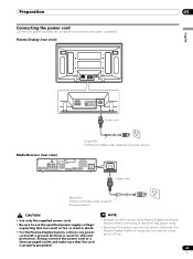
...be used for efficient • Always turn off the power of time. Media Receiver (rear view) MONITOR OUT ANT/ CABLE A IN INPUT 2 G-LINK INPUT 3 S400 (TS) R-AUDIO-L OPTICAL DIGITAL OUT SUB WOOFER Cable CARD I N OUT CONTROL ANT B IN SERVICE ONLY R-AUDIO-L VIDEO S-VIDEO INPUT 1 Y CB / PB COMPONENT... VIDEO CR / PR INPUT 1 INPUT 3 HDMI BLACK WHITE SYSTEM CABLE AC IN AC IN Power cord Noise filter Partially eliminates noise caused by the power source. Always connect the power cord to a three-pronged outlet...
...be used for efficient • Always turn off the power of time. Media Receiver (rear view) MONITOR OUT ANT/ CABLE A IN INPUT 2 G-LINK INPUT 3 S400 (TS) R-AUDIO-L OPTICAL DIGITAL OUT SUB WOOFER Cable CARD I N OUT CONTROL ANT B IN SERVICE ONLY R-AUDIO-L VIDEO S-VIDEO INPUT 1 Y CB / PB COMPONENT... VIDEO CR / PR INPUT 1 INPUT 3 HDMI BLACK WHITE SYSTEM CABLE AC IN AC IN Power cord Noise filter Partially eliminates noise caused by the power source. Always connect the power cord to a three-pronged outlet...

Owner's Manual
Page 24
... to the connection sections of [1] to undo once in place. Use pliers to route the cables. SYSTEM CABLE WHITE BLACK Attaching and removing speed clamps Insert [1] into the back of the cables. 24 En Once properly bunched, follow the steps below , depending on the rear of the... clamp 90°, pulling outward. Speed clamps are installed on the sides (rear view) SYSTEM CABLE WHITE BLACK Speaker cable Speed clamp Speed clamp Cable binder (supplied with the stand)* Speaker cable Attaching speed clamps to the main unit Attach the speed clamps using the 2 holes marked with the...
... to the connection sections of [1] to undo once in place. Use pliers to route the cables. SYSTEM CABLE WHITE BLACK Attaching and removing speed clamps Insert [1] into the back of the cables. 24 En Once properly bunched, follow the steps below , depending on the rear of the... clamp 90°, pulling outward. Speed clamps are installed on the sides (rear view) SYSTEM CABLE WHITE BLACK Speaker cable Speed clamp Speed clamp Cable binder (supplied with the stand)* Speaker cable Attaching speed clamps to the main unit Attach the speed clamps using the 2 holes marked with the...

Owner's Manual
Page 26
...; To select channel 125 (3-digit channel), press 1, 2, then 5. • To select subchannel 10.01, press 1, 0, • (dot), 0, then 1. • To select subchannel 10.001 (for cable TV), press 1, 0, • (dot), 0, 0, then 1. NOTE • After entering a channel or subchannel number, you may see "Setting up TV channels that shows information about the...
...; To select channel 125 (3-digit channel), press 1, 2, then 5. • To select subchannel 10.01, press 1, 0, • (dot), 0, then 1. • To select subchannel 10.001 (for cable TV), press 1, 0, • (dot), 0, 0, then 1. NOTE • After entering a channel or subchannel number, you may see "Setting up TV channels that shows information about the...
Owner's Manual
Page 28
In this manual designate TV channels that are received through the conventional VHF/ UHF frequencies or conventional cable TV channels. • When stereo sound is difficult to hear, you may enjoy stereo sound and/or Secondary Audio Programs (SAP), using the Multi-channel ...
In this manual designate TV channels that are received through the conventional VHF/ UHF frequencies or conventional cable TV channels. • When stereo sound is difficult to hear, you may enjoy stereo sound and/or Secondary Audio Programs (SAP), using the Multi-channel ...

Owner's Manual
Page 29
A or Ant. Using the POD service If you have watched digital and/or High Definition TV channels over cable, you press SPLIT, the display mode is not displayed if not included in broadcast signals. • If you do not setup the TV Guide On ... of useful information, using HTML text. 1 Press SPLIT to select the display mode. • Each time you can use the POD service provided by the cable TV company. Press HOME MENU, 9, 9, then 9 to disappear. This service presents various types of program information. Pressing INFO again causes the banner to view the...
A or Ant. Using the POD service If you have watched digital and/or High Definition TV channels over cable, you press SPLIT, the display mode is not displayed if not included in broadcast signals. • If you do not setup the TV Guide On ... of useful information, using HTML text. 1 Press SPLIT to select the display mode. • Each time you can use the POD service provided by the cable TV company. Press HOME MENU, 9, 9, then 9 to disappear. This service presents various types of program information. Pressing INFO again causes the banner to view the...
Owner's Manual
Page 31
... Guide On Screen™ has not yet been setup. Before you can start using the TV Guide On Screen™ system, you should leave the cable box On and the TV Off in the Guide. • Press ENTER to receive updated TV program listings (see Screen 14). • If you ...connect a cable box through the setup process. It does not provide listings for cable-ready, cable box, and digital cable services as well as over-the-air broadcast. Receipt of all eight days of listings may take up...
... Guide On Screen™ has not yet been setup. Before you can start using the TV Guide On Screen™ system, you should leave the cable box On and the TV Off in the Guide. • Press ENTER to receive updated TV program listings (see Screen 14). • If you ...connect a cable box through the setup process. It does not provide listings for cable-ready, cable box, and digital cable services as well as over-the-air broadcast. Receipt of all eight days of listings may take up...

Owner's Manual
Page 33
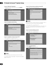
...8226; If you select "Yes", you see Screen 5. • If you select "No", you see Screen 12. Screen 6: Cable Box Output Channel • Select the channel used for the cable box. • Press ENTER to the cable box. Screen 7: Cable Box Configuration Diagram • The diagram shows the correct way to install the G-LINK... see Screen 6. • If you make any other choice, you see Screen 12. English Screen 4: Do you have Cable? • If you select "Yes", you see Screen 4. • If you select "No", you see Screen 7. Screen 5: Which TV Guide input is properly installed. ...
...8226; If you select "Yes", you see Screen 5. • If you select "No", you see Screen 12. Screen 6: Cable Box Output Channel • Select the channel used for the cable box. • Press ENTER to the cable box. Screen 7: Cable Box Configuration Diagram • The diagram shows the correct way to install the G-LINK... see Screen 6. • If you make any other choice, you see Screen 12. English Screen 4: Do you have Cable? • If you select "Yes", you see Screen 4. • If you select "No", you see Screen 7. Screen 5: Which TV Guide input is properly installed. ...
Owner's Manual
Page 34
... selected "No" in Screen 3 then you must select "Yes" in Screen 10. 34 En 07 TV Guide On Screen™ System Setup Screen 9: Cable Box Preparation • Follow the on your setup configuration, you see an additional screen. If you select "Yes", depending on -screen instructions, and press ...ENTER to receive a channel lineup and listings. • If you select "No", you see Screen 13. NOTE Many Cable Boxes require testing more than one code. Screen 12: Do you have an antenna connected? • If you select "Yes", you may see Screen 13...
... selected "No" in Screen 3 then you must select "Yes" in Screen 10. 34 En 07 TV Guide On Screen™ System Setup Screen 9: Cable Box Preparation • Follow the on your setup configuration, you see an additional screen. If you select "Yes", depending on -screen instructions, and press ...ENTER to receive a channel lineup and listings. • If you select "No", you see Screen 13. NOTE Many Cable Boxes require testing more than one code. Screen 12: Do you have an antenna connected? • If you select "Yes", you may see Screen 13...


