
User Manual
Page 2
Check for the ASTA mark or the BSI mark on the power supply cord of this unit should be used until a replacement cover is inserted into any doubt, please consult a qualified electrician. A replacement fuse cover can be removed and the plug cut off and disposed of safely. If the fitted moulded plug is supplied with the letter N or coloured BLACK. If in this appliance may not correspond with the letter L or coloured RED. IMPORTANT: THE MOULDED PLUG This appliance is unsuitable for your plug, proceed as shown below. If the plug contains a removable fuse cover, you ...
Check for the ASTA mark or the BSI mark on the power supply cord of this unit should be used until a replacement cover is inserted into any doubt, please consult a qualified electrician. A replacement fuse cover can be removed and the plug cut off and disposed of safely. If the fitted moulded plug is supplied with the letter N or coloured BLACK. If in this appliance may not correspond with the letter L or coloured RED. IMPORTANT: THE MOULDED PLUG This appliance is unsuitable for your plug, proceed as shown below. If the plug contains a removable fuse cover, you ...
User Manual
Page 3
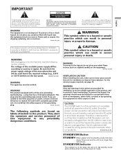
To prevent a fire or shock hazard, do not place any naked flame sources (such as a vase or flower pot) or expose it from overheating. If you will need to a hazard or unsafe practice which can result in for the first time, read the following symbols are unable to shut down all power from the AC outlet in the power-on mode. CAUTION This symbol refers to unplug it from the AC outlet when left unused for a long period of time (for ventilation to the product. WARNING Slots and openings in severe personal injury or death. This product complies with items (...
To prevent a fire or shock hazard, do not place any naked flame sources (such as a vase or flower pot) or expose it from overheating. If you will need to a hazard or unsafe practice which can result in for the first time, read the following symbols are unable to shut down all power from the AC outlet in the power-on mode. CAUTION This symbol refers to unplug it from the AC outlet when left unused for a long period of time (for ventilation to the product. WARNING Slots and openings in severe personal injury or death. This product complies with items (...

User Manual
Page 4
... regarding batteries 20 Allowed operation range of the power plug and power outlet may sometimes differ from that shown in a safe place for buying this Pioneer product. Please read through these operating instructions so you have finished reading the instructions, put them away in the explanatory drawings. Contents Contents Thank you...
... regarding batteries 20 Allowed operation range of the power plug and power outlet may sometimes differ from that shown in a safe place for buying this Pioneer product. Please read through these operating instructions so you have finished reading the instructions, put them away in the explanatory drawings. Contents Contents Thank you...
User Manual
Page 5
English Contents 11 Enjoying through External Equipment Watching a decoder or VCR image ....... 33 Connecting a decoder or VCR 33 Displaying a decoder or VCR image .. 33 Using HDMI Input 33 Connecting HDMI equipment 34 Using DVI Input 35 Connecting DVI equipment 35 Watching a DVD image 35 Connecting a DVD player 35 Displaying a DVD image 36 Enjoying a game console or watching camcorder images 36 Connecting a game console or camcorder 36 Displaying an image from the game console or camcorder 36 Watching an image from a personal computer 36 Connecting a personal computer ...... 36 ...
English Contents 11 Enjoying through External Equipment Watching a decoder or VCR image ....... 33 Connecting a decoder or VCR 33 Displaying a decoder or VCR image .. 33 Using HDMI Input 33 Connecting HDMI equipment 34 Using DVI Input 35 Connecting DVI equipment 35 Watching a DVD image 35 Connecting a DVD player 35 Displaying a DVD image 36 Enjoying a game console or watching camcorder images 36 Connecting a game console or camcorder 36 Displaying an image from the game console or camcorder 36 Watching an image from a personal computer 36 Connecting a personal computer ...... 36 ...
User Manual
Page 6
... limit its use of the unit to its lifetime, the luminosity of the Pioneer PDP-5000EX Plasma Display will diminish very slowly, such as very precise and highly advanced technology. PIONEER will automatically power off in the future during the manufacturing process and in order... cells. • Panel generated sounds, examples: Fan motor noise, and electrical circuit humming / glass panel buzzing Installation guidelines The Pioneer PureVision PDP-5000EX Plasma Display incorporates a very thin design. This product should not be assured of a high quality Plasma Display with long-life and...
... limit its use of the unit to its lifetime, the luminosity of the Pioneer PDP-5000EX Plasma Display will diminish very slowly, such as very precise and highly advanced technology. PIONEER will automatically power off in the future during the manufacturing process and in order... cells. • Panel generated sounds, examples: Fan motor noise, and electrical circuit humming / glass panel buzzing Installation guidelines The Pioneer PureVision PDP-5000EX Plasma Display incorporates a very thin design. This product should not be assured of a high quality Plasma Display with long-life and...
User Manual
Page 7
... required specifications, it with a clean soft cloth (e.g., cotton and flannel). The screen is dimmed when a still image is not affected. Pioneer Plasma Display panels contain a very large number of cells. (Depending on the screen for an extended period of noise. When condensation takes ... the product with rubber or vinyl products for a long period of the Plasma Display. Important User Guidance Information 01 English CAUTION PIONEER bears no responsibility for any damage arising from this product. If this happens, place that equipment may result in malfunction. Plasma Display...
... required specifications, it with a clean soft cloth (e.g., cotton and flannel). The screen is dimmed when a still image is not affected. Pioneer Plasma Display panels contain a very large number of cells. (Depending on the screen for an extended period of noise. When condensation takes ... the product with rubber or vinyl products for a long period of the Plasma Display. Important User Guidance Information 01 English CAUTION PIONEER bears no responsibility for any damage arising from this product. If this happens, place that equipment may result in malfunction. Plasma Display...
User Manual
Page 8
This includes those images displayed in the following two cases. 1 After-image lagging due to remaining electrical load When image patterns with general household waste. Such images may become less noticeable if moving images are displayed. By doing so you will not disappear completely. • The energy save function can be set to help prevent damage from screen burning (see page 29). The after -image lagging. If the same image is displayed continuously for several days, a permanent after -image lagging may occur due to dispose this product, do not mix it with very high peak ...
This includes those images displayed in the following two cases. 1 After-image lagging due to remaining electrical load When image patterns with general household waste. Such images may become less noticeable if moving images are displayed. By doing so you will not disappear completely. • The energy save function can be set to help prevent damage from screen burning (see page 29). The after -image lagging. If the same image is displayed continuously for several days, a permanent after -image lagging may occur due to dispose this product, do not mix it with very high peak ...
User Manual
Page 9
However, improper use the supplied cleaning cloth or other heatgenerating products (including amplifiers). 22. Keep this product is made of glass. All warnings on a wall, be sure to follow the manufacturer's instructions. Follow instructions - Cleaning - To clean the product, use can result in electric shock and/or fire. Use of objects and liquids - When mounting the product on the product and in the instructions must be observed closely. 4. When relocating the product placed on them or 02 objects from heat sources such as described in the operating instructions. This...
However, improper use the supplied cleaning cloth or other heatgenerating products (including amplifiers). 22. Keep this product is made of glass. All warnings on a wall, be sure to follow the manufacturer's instructions. Follow instructions - Cleaning - To clean the product, use can result in electric shock and/or fire. Use of objects and liquids - When mounting the product on the product and in the instructions must be observed closely. 4. When relocating the product placed on them or 02 objects from heat sources such as described in the operating instructions. This...
User Manual
Page 10
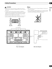
... be sure to install it very unstable when stood on rear surface wall, etc. 02 Safety Precautions Installation using the optional PIONEER stand or installation bracket • Please be sure to request installation or mounting of this unit or the installation bracket by ...installation specialist or the dealer where purchased. • When installing, be sure to use of parts and accessories manufactured by other than the PIONEER stand or installation bracket (sold separately) • When possible, please install using accessories other companies. • For custom installation, please...
... be sure to install it very unstable when stood on rear surface wall, etc. 02 Safety Precautions Installation using the optional PIONEER stand or installation bracket • Please be sure to request installation or mounting of this unit or the installation bracket by ...installation specialist or the dealer where purchased. • When installing, be sure to use of parts and accessories manufactured by other than the PIONEER stand or installation bracket (sold separately) • When possible, please install using accessories other companies. • For custom installation, please...
User Manual
Page 11
also do not use them as means of hanging the display; a hole Air vents (fan) a hole Main unit Center line Attaching surface Installation bracket, etc. To ensure safety, the mounting screws should be tightened to a minimum torque of 2N·m (20 kgf·cm) when reattaching the handles. • When moving the display, it should always be carried by anyone other than the professional installation technician or service personnel. • If handles must be removed due to prevent tipping over (see illustration). a hole Bolt 12 mm to move the Plasma Display by holding the...
also do not use them as means of hanging the display; a hole Air vents (fan) a hole Main unit Center line Attaching surface Installation bracket, etc. To ensure safety, the mounting screws should be tightened to a minimum torque of 2N·m (20 kgf·cm) when reattaching the handles. • When moving the display, it should always be carried by anyone other than the professional installation technician or service personnel. • If handles must be removed due to prevent tipping over (see illustration). a hole Bolt 12 mm to move the Plasma Display by holding the...
User Manual
Page 12
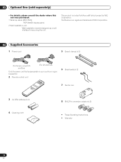
... Optional line (sold separately) Optional line (sold separately) • For details, please consult the dealer where this unit was purchased. 1 Table top stand (PDK-TS23): PDP-5000EX display stand. 2 Wall installation unit: Wall installation bracket designed as a wall interface for securing the unit. FontAvenue is a registered trademark of NEC Corporation. 04 Supplied...
... Optional line (sold separately) Optional line (sold separately) • For details, please consult the dealer where this unit was purchased. 1 Table top stand (PDK-TS23): PDP-5000EX display stand. 2 Wall installation unit: Wall installation bracket designed as a wall interface for securing the unit. FontAvenue is a registered trademark of NEC Corporation. 04 Supplied...
User Manual
Page 13
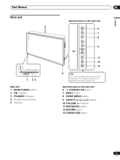
button 12 RETURN button 13 SCREEN SIZE button 13 En Operation panel on the main unit 6 7 8 9 10 11 12 13 4 Note The unit's operating panel will become inoperable if connected speakers are installed too near the main unit. Part Names Part Names Main unit 5 POWER ON STANDBY 1 23 Main unit 1 MAIN POWER switch 2 ON indicator 3 STANDBY indicator 4 Remote control sensor 5 Handles 05 English Operation panel on the main unit 6 STANDBY/ON button 7 INPUT button 8 HOME MENU button 9 ADJUST ( / / / ) buttons 10 VOLUME +/- buttons 11 ENTER/DISP.
button 12 RETURN button 13 SCREEN SIZE button 13 En Operation panel on the main unit 6 7 8 9 10 11 12 13 4 Note The unit's operating panel will become inoperable if connected speakers are installed too near the main unit. Part Names Part Names Main unit 5 POWER ON STANDBY 1 23 Main unit 1 MAIN POWER switch 2 ON indicator 3 STANDBY indicator 4 Remote control sensor 5 Handles 05 English Operation panel on the main unit 6 STANDBY/ON button 7 INPUT button 8 HOME MENU button 9 ADJUST ( / / / ) buttons 10 VOLUME +/- buttons 11 ENTER/DISP.
User Manual
Page 14
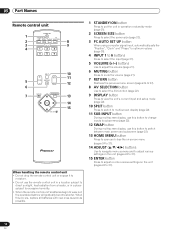
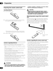
05 Part Names Remote control unit STANDBY/ON 1 SCREEN AUTO AV SIZE SETUP DISPLAY SELECTION 2 PC 8 3 INPUT 9 4 1 2 3 4 5 6 SPLIT SUB INPUT 5 VOLUME MUTING SWAP 6 10 11 12 RETURN 7 HOME MENU 13 ENTER AXD1535 14 15 When handling the remote control unit • Do not drop the remote control unit or expose it to moisture. • Do not use the remote control unit in a location subject to direct sunlight, heat radiation from a heater, or in operation or standby mode (page 21). 2 SCREEN SIZE button Press to select the screen size (page 23). 3 PC AUTO SET UP button ...
05 Part Names Remote control unit STANDBY/ON 1 SCREEN AUTO AV SIZE SETUP DISPLAY SELECTION 2 PC 8 3 INPUT 9 4 1 2 3 4 5 6 SPLIT SUB INPUT 5 VOLUME MUTING SWAP 6 10 11 12 RETURN 7 HOME MENU 13 ENTER AXD1535 14 15 When handling the remote control unit • Do not drop the remote control unit or expose it to moisture. • Do not use the remote control unit in a location subject to direct sunlight, heat radiation from a heater, or in operation or standby mode (page 21). 2 SCREEN SIZE button Press to select the screen size (page 23). 3 PC AUTO SET UP button ...
User Manual
Page 15
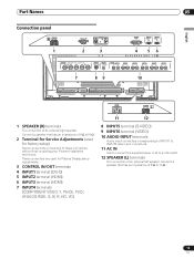
... for factory setup) Never connect any component to 16 Ω. 15 En L 1 SPEAKER (R) terminals For connection of 8 Ω to these connectors without first consulting your Pioneer installation technician. Connect a speaker that has an impedance of an external right speaker.
... for factory setup) Never connect any component to 16 Ω. 15 En L 1 SPEAKER (R) terminals For connection of 8 Ω to these connectors without first consulting your Pioneer installation technician. Connect a speaker that has an impedance of an external right speaker.
User Manual
Page 16
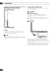
... required for display, and the contour involves a raised projection. 06 Preparation Preparation Installing the Plasma Display Over 50 cm Over 10 cm Using the optional PIONEER stand • For details on installation, refer to +40 ˚C; less than 85 % RH (cooling vents not blocked) Do not install this area to impact...
... required for display, and the contour involves a raised projection. 06 Preparation Preparation Installing the Plasma Display Over 50 cm Over 10 cm Using the optional PIONEER stand • For details on installation, refer to +40 ˚C; less than 85 % RH (cooling vents not blocked) Do not install this area to impact...
User Manual
Page 17
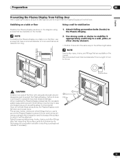
Failure to do not take these precautions, the Plasma Display could result in personal injury and physical damage. The screws, hooks, chains and other fittings that have a nominal diameter of accidents. Preparation 06 English Preventing the Plasma Display from overturning will vary according to the composition and thickness of the surface to which it will not fall down and cause injury. Attach falling prevention bolts (hooks) to ensure that are available on the left and right sides. If you use screws that you do so could fall over. NOTE To stabilize the Plasma ...
Failure to do not take these precautions, the Plasma Display could result in personal injury and physical damage. The screws, hooks, chains and other fittings that have a nominal diameter of accidents. Preparation 06 English Preventing the Plasma Display from overturning will vary according to the composition and thickness of the surface to which it will not fall down and cause injury. Attach falling prevention bolts (hooks) to ensure that are available on the left and right sides. If you use screws that you do so could fall over. NOTE To stabilize the Plasma ...
User Manual
Page 18
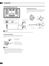
Proper sound will not be sure to connect the speaker's positive (+) and negative (-) terminals to the same terminals on the cable. Connecting the speakers This unit is equipped with 8 Ω to 16 Ω impedance. 18 En To AC IN As close tab firmly to secure the wire in place. Use the supplied cable tie to prevent the ferrite core from its outlet. L Europe, except UK and Eire Ferrite core Cable tie To power outlet UK and Eire AC power cord NOTE • When not using this unit for extended periods, disconnect the power cord from slipping on this unit. Then, close...
Proper sound will not be sure to connect the speaker's positive (+) and negative (-) terminals to the same terminals on the cable. Connecting the speakers This unit is equipped with 8 Ω to 16 Ω impedance. 18 En To AC IN As close tab firmly to secure the wire in place. Use the supplied cable tie to prevent the ferrite core from its outlet. L Europe, except UK and Eire Ferrite core Cable tie To power outlet UK and Eire AC power cord NOTE • When not using this unit for extended periods, disconnect the power cord from slipping on this unit. Then, close...

User Manual
Page 19
Speed clamps are connected, follow the following steps to route cables. * As viewed from the rear of cables. To attach the speed clamps to be placed on the ends of the display. Once components are designed to be routed to route cables Speed clamps and bead bands are included with this unit for bunching cables together. To remove speed clamps Using pliers, twist the clamp 90° and pull it outward. Please attach carefully. 2. Do not allow excessive stress to the main unit Connect the speed clamps using the provided speed clamps. Preparation 06 English How to the ...
Speed clamps are connected, follow the following steps to route cables. * As viewed from the rear of cables. To attach the speed clamps to be placed on the ends of the display. Once components are designed to be routed to route cables Speed clamps and bead bands are included with this unit for bunching cables together. To remove speed clamps Using pliers, twist the clamp 90° and pull it outward. Please attach carefully. 2. Do not allow excessive stress to the main unit Connect the speed clamps using the provided speed clamps. Preparation 06 English How to the ...
User Manual
Page 20
It can result in chemical leakage or explosion. In such case, change the angle of the lighting or Plasma Display, or operate the remote control unit closer to storage conditions. • If you replace the batteries, use of batteries can also reduce the life or performance of near a heater. If you place such equipment operated through infrared remote control as inside a car or of its rays or limiting its operational distance. WARNING • Depending on the installation surroundings, this unit's remote control unit may have a shorter life expectancy due to the remote control...
It can result in chemical leakage or explosion. In such case, change the angle of the lighting or Plasma Display, or operate the remote control unit closer to storage conditions. • If you replace the batteries, use of batteries can also reduce the life or performance of near a heater. If you place such equipment operated through infrared remote control as inside a car or of its rays or limiting its operational distance. WARNING • Depending on the installation surroundings, this unit's remote control unit may have a shorter life expectancy due to the remote control...
User Manual
Page 21
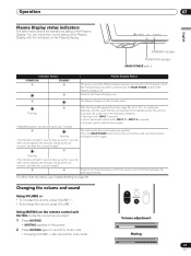
You can check the current status of the Plasma Display with the result that the unit switched to "On", no signal was detected, with the indicators on . The Plasma Display is on the Plasma Display. 07 POWER ON STANDBY English STANDBY indicator POWER ON indicator MAIN POWER switch Indicator Status POWER ON STANDBY Plasma Display Status The power cord of the remote control unit's INPUT 1 to INPUT 6 is pressed; • An input signal is detected once again. (Repeatedly lights 1 second, then goes out 1 second) Flashing (The indicator will repeat.) Power to the Plasma Display is...
You can check the current status of the Plasma Display with the result that the unit switched to "On", no signal was detected, with the indicators on . The Plasma Display is on the Plasma Display. 07 POWER ON STANDBY English STANDBY indicator POWER ON indicator MAIN POWER switch Indicator Status POWER ON STANDBY Plasma Display Status The power cord of the remote control unit's INPUT 1 to INPUT 6 is pressed; • An input signal is detected once again. (Repeatedly lights 1 second, then goes out 1 second) Flashing (The indicator will repeat.) Power to the Plasma Display is...