
Operating Instructions
Page 4
...your enclosed warranty card and keep it in a particular installation. However, there is for a Class B digital device, pursuant to Part 15 of the following symbols are designed to provide reasonable protection against harmful interference in severe personal injury or death. Increase the ...associated with accessories sold with electric appliances such as vase, flower pot, cosmetics container and medicine bottle etc. NO USER-SERVICEABLE PARTS INSIDE. Please write this serial number on this apparatus, such as radios and televisions, use shielded cables and connectors for help....
...your enclosed warranty card and keep it in a particular installation. However, there is for a Class B digital device, pursuant to Part 15 of the following symbols are designed to provide reasonable protection against harmful interference in severe personal injury or death. Increase the ...associated with accessories sold with electric appliances such as vase, flower pot, cosmetics container and medicine bottle etc. NO USER-SERVICEABLE PARTS INSIDE. Please write this serial number on this apparatus, such as radios and televisions, use shielded cables and connectors for help....
Operating Instructions
Page 5
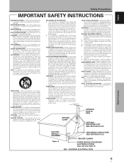
... ELECTRIC SERVICE EQUIPMENT Figure A GROUNDING CONDUCTORS (NEC SECTION 810-21) GROUND CLAMPS POWER SERVICE GROUNDING ELECTRODE SYSTEM (NEC ART 250, PART H) NEC - NATIONAL ELECTRICAL CODE Safety Precautions iii En HEED WARNINGS - GROUNDING OR POLARIZATION ÷ If this product on or pinched...heat registers, stoves, or other hazards. Do not overload wall outlets, extension cords, or integral convenience receptacles as the original part. REPLACEMENT PARTS - Upon completion of the lead-in fire, electric shock, or other similar surface. in a stable location. Do not ...
... ELECTRIC SERVICE EQUIPMENT Figure A GROUNDING CONDUCTORS (NEC SECTION 810-21) GROUND CLAMPS POWER SERVICE GROUNDING ELECTRODE SYSTEM (NEC ART 250, PART H) NEC - NATIONAL ELECTRICAL CODE Safety Precautions iii En HEED WARNINGS - GROUNDING OR POLARIZATION ÷ If this product on or pinched...heat registers, stoves, or other hazards. Do not overload wall outlets, extension cords, or integral convenience receptacles as the original part. REPLACEMENT PARTS - Upon completion of the lead-in fire, electric shock, or other similar surface. in a stable location. Do not ...
Operating Instructions
Page 6
... in Canada, please contact a Pioneer Canadian Authorized Dealer to the following address: Pioneer Electronics of the FCC Rules. and you wish to locate the nearest Pioneer Authorized Independent Service Company, or if you wish to purchase replacement parts, operating instructions, service manuals,...OF CONFORMITY This device complies with Video Card Model Number: PDP-504CMX / PDP-434CMX (Plasma Display) PDA-5003/PDA-5004 (Video Card) Product Category: Class B Personal Computers & Peripherals Responsible Party Name: PIONEER ELECTRONICS (USA) INC. For warranty information please see ...
... in Canada, please contact a Pioneer Canadian Authorized Dealer to the following address: Pioneer Electronics of the FCC Rules. and you wish to locate the nearest Pioneer Authorized Independent Service Company, or if you wish to purchase replacement parts, operating instructions, service manuals,...OF CONFORMITY This device complies with Video Card Model Number: PDP-504CMX / PDP-434CMX (Plasma Display) PDA-5003/PDA-5004 (Video Card) Product Category: Class B Personal Computers & Peripherals Responsible Party Name: PIONEER ELECTRONICS (USA) INC. For warranty information please see ...
Operating Instructions
Page 7
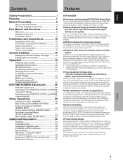
English Contents Safety Precautions i Features 1 Before Proceeding 3 How to use this manual 3 Checking supplied accessories 5 Part Names and Functions 6 Main unit 6 Remote control unit 7 Connection panel 8 Installation and Connections 10 Installation of the unit 10 Connection to a... 19 Selecting input source 19 Adjusting sound volume 20 Muting the sound 20 Confirming current status 20 Changing screen size 21 Enlarging one part of the screen (POINT ZOOM 22 Multiscreen display 23 Automatic power-off (POWER MANAGEMENT 24 PICTURE/SCREEN Adjustment 25 PICTURE adjustment 25 ...
English Contents Safety Precautions i Features 1 Before Proceeding 3 How to use this manual 3 Checking supplied accessories 5 Part Names and Functions 6 Main unit 6 Remote control unit 7 Connection panel 8 Installation and Connections 10 Installation of the unit 10 Connection to a... 19 Selecting input source 19 Adjusting sound volume 20 Muting the sound 20 Confirming current status 20 Changing screen size 21 Enlarging one part of the screen (POINT ZOOM 22 Multiscreen display 23 Automatic power-off (POWER MANAGEMENT 24 PICTURE/SCREEN Adjustment 25 PICTURE adjustment 25 ...
Operating Instructions
Page 9
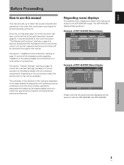
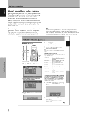
...be beneficial to look over the section "Part Names and Functions" starting on page 10 covers all the parts have been received (page 5), it has been confirmed that the actual contents displayed are those for both the PDP-504CMX and PDP-434CMX. The remainder of the plasma display ...SET ENTER MENU EXIT Please note that all the necessary points regarding installation of the plasma display and connections to a wide variety of PDP-434CMX Menu Display: MENU PICTURE CONTRAST BRIGHTNESS R.LEVEL G.LEVEL B.LEVEL H.ENHANCE V. English Before Proceeding How to use this manual This manual ...
...be beneficial to look over the section "Part Names and Functions" starting on page 10 covers all the parts have been received (page 5), it has been confirmed that the actual contents displayed are those for both the PDP-504CMX and PDP-434CMX. The remainder of the plasma display ...SET ENTER MENU EXIT Please note that all the necessary points regarding installation of the plasma display and connections to a wide variety of PDP-434CMX Menu Display: MENU PICTURE CONTRAST BRIGHTNESS R.LEVEL G.LEVEL B.LEVEL H.ENHANCE V. English Before Proceeding How to use this manual This manual ...
Operating Instructions
Page 10
... direction. MENU PICTURE SCREEN CONTRAST : BRIGHTNESS : R.LEVEL : G.LEVEL : B.LEVEL : H.ENHANCE : V. E N H A N C E : SETUP 0 0 0 0 0 0 0 PICTURE RESET INPUT1 OPTION 4 Press the SET button. BRIGHTNESS Adjust so that the dark parts of those found on the screen item displayed and its proper operating order. R. B. V. SET ENTER MENU EXIT 3 Use the 2/3 buttons to display the menu screen...
... direction. MENU PICTURE SCREEN CONTRAST : BRIGHTNESS : R.LEVEL : G.LEVEL : B.LEVEL : H.ENHANCE : V. E N H A N C E : SETUP 0 0 0 0 0 0 0 PICTURE RESET INPUT1 OPTION 4 Press the SET button. BRIGHTNESS Adjust so that the dark parts of those found on the screen item displayed and its proper operating order. R. B. V. SET ENTER MENU EXIT 3 Use the 2/3 buttons to display the menu screen...
Operating Instructions
Page 12
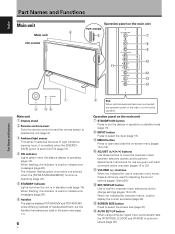
...). 5 STANDBY indicator Lights red when the unit is used to indicate error messages (page 36). When flashing, the indicator is operating (page 19). Part Names and Functions 1 3 45 Main unit 1 Display stand 2 Remote control sensor Point the remote control toward the remote sensor to operate the unit ...page 31). 4 ON indicator Lights green when the plasma display is used to indicate error messages (page 36). 6 Handles The plasma displays PDP-504CMX and PDP-434CMX utilize differing methods of light inside the viewing room; it is enabled when the [ENERGY SAVE] option is set status (page 20). ...
...). 5 STANDBY indicator Lights red when the unit is used to indicate error messages (page 36). When flashing, the indicator is operating (page 19). Part Names and Functions 1 3 45 Main unit 1 Display stand 2 Remote control sensor Point the remote control toward the remote sensor to operate the unit ...page 31). 4 ON indicator Lights green when the plasma display is used to indicate error messages (page 36). 6 Handles The plasma displays PDP-504CMX and PDP-434CMX utilize differing methods of light inside the viewing room; it is enabled when the [ENERGY SAVE] option is set status (page 20). ...

Operating Instructions
Page 13
...23). 8 MUTING button Press to mute the volume (page 20). 9 AUTO SET UP button When using PinP mode with new ones as soon as possible. Part Names and Functions 1 SCREEN SIZE button Press to select the screen size (page 21). 2 INPUT buttons Press to select the input (page 19). 3 ... the unit (pages 16 to 33). 6 SUB INPUT button During multi-screen display, use this button to switch between main screen and subscreen (page 23). ! Part Names and Functions 7 En PIP SHIFT button When using computer signal input, automatically sets the [POSITION], [CLOCK] and [PHASE] to optimum values (page 26). ...
...23). 8 MUTING button Press to mute the volume (page 20). 9 AUTO SET UP button When using PinP mode with new ones as soon as possible. Part Names and Functions 1 SCREEN SIZE button Press to select the screen size (page 21). 2 INPUT buttons Press to select the input (page 19). 3 ... the unit (pages 16 to 33). 6 SUB INPUT button During multi-screen display, use this button to switch between main screen and subscreen (page 23). ! Part Names and Functions 7 En PIP SHIFT button When using computer signal input, automatically sets the [POSITION], [CLOCK] and [PHASE] to optimum values (page 26). ...
Operating Instructions
Page 14
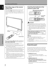
...screen will gradually become shorter as the batteries begin to the picture displayed. 8 En CAUTION ¶ Insert batteries so that apply in your Pioneer installation technician. For instructions regarding connections, consult the pages noted in a fire. When disposing of used for a long period of time (1... month or more), remove the batteries from receiving the signal entirely. English Part Names and Functions Operating range of the remote control unit When operating the remote control unit, point it at the remote sensor (Î)...
...screen will gradually become shorter as the batteries begin to the picture displayed. 8 En CAUTION ¶ Insert batteries so that apply in your Pioneer installation technician. For instructions regarding connections, consult the pages noted in a fire. When disposing of used for a long period of time (1... month or more), remove the batteries from receiving the signal entirely. English Part Names and Functions Operating range of the remote control unit When operating the remote control unit, point it at the remote sensor (Î)...
Operating Instructions
Page 15
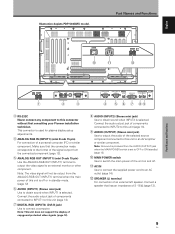
L = Part Names and Functions R SPEAKER 8+Ω ~16Ω- 1 IN OUT COMBINATION 2 RS-232C 3 ANALOG RGB IN D-Sub ANALOG RGB ...from the ANALOG RGB OUT (INPUT1) terminal when the main power of a personal computer (PC) or similar component. English Illustration depicts PDP-504CMX model. Part Names and Functions POWER OFF ON AC IN 0 - SPEAKER 8+Ω ~16Ω- Connect the audio output jack of components connected.... 4 ANALOG RGB IN (INPUT1) (mini D-sub 15 pin) For connection of this connector without first consulting your Pioneer installation technician.
L = Part Names and Functions R SPEAKER 8+Ω ~16Ω- 1 IN OUT COMBINATION 2 RS-232C 3 ANALOG RGB IN D-Sub ANALOG RGB ...from the ANALOG RGB OUT (INPUT1) terminal when the main power of a personal computer (PC) or similar component. English Illustration depicts PDP-504CMX model. Part Names and Functions POWER OFF ON AC IN 0 - SPEAKER 8+Ω ~16Ω- Connect the audio output jack of components connected.... 4 ANALOG RGB IN (INPUT1) (mini D-sub 15 pin) For connection of this connector without first consulting your Pioneer installation technician.

Operating Instructions
Page 16
...cooperate when unpacking, moving , or installing the display. CAUTION This unit incorporates a thin design. Front Rear PDP-504CMX: 798 mm (31-7/16 in.) (Bolt hole thread pitch) PDP-434CMX: 880 mm (31-7/16 in .) 2 Set this size bolt can be held responsible for wall-mount ...when stood on a flat, unwarped surface. Installation and Connections English Installation and Connections Installation of the unit Installation using parts and accessories manufactured by PIONEER. PIONEER will not be used.) CAUTION This display unit weighs at least 30 kg (67 lbs) and has little frontto...
...cooperate when unpacking, moving , or installing the display. CAUTION This unit incorporates a thin design. Front Rear PDP-504CMX: 798 mm (31-7/16 in.) (Bolt hole thread pitch) PDP-434CMX: 880 mm (31-7/16 in .) 2 Set this size bolt can be held responsible for wall-mount ...when stood on a flat, unwarped surface. Installation and Connections English Installation and Connections Installation of the unit Installation using parts and accessories manufactured by PIONEER. PIONEER will not be used.) CAUTION This display unit weighs at least 30 kg (67 lbs) and has little frontto...
Operating Instructions
Page 28
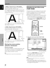
... The image cannot be adjusted. Display is highly faithful to adjust the vertical position of the video image on the screen. 5 ZOOM (*Supported only on PDP-434CMX) The [ZOOM] setting is pressed, the zoom ratio alternates in infringement of the copyrights of [x 1.5], [x 2], and [x 3]. This adjusted position cannot, ...confirmed by ratios of the image owners. The Zoom-Navi subscreen is displayed for about three seconds whenever the POINT ZOOM button, one part of the screen (POINT ZOOM) This plasma display allows enlarging of the screen image by viewing the Zoom-Navi subscreen at the ...
... The image cannot be adjusted. Display is highly faithful to adjust the vertical position of the video image on the screen. 5 ZOOM (*Supported only on PDP-434CMX) The [ZOOM] setting is pressed, the zoom ratio alternates in infringement of the copyrights of [x 1.5], [x 2], and [x 3]. This adjusted position cannot, ...confirmed by ratios of the image owners. The Zoom-Navi subscreen is displayed for about three seconds whenever the POINT ZOOM button, one part of the screen (POINT ZOOM) This plasma display allows enlarging of the screen image by viewing the Zoom-Navi subscreen at the ...
Operating Instructions
Page 29
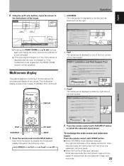
... main screen image will now appear in the following order: 3 2-SCREEN 3 PinP 3 PoutP 3 OFF 2 Press the remote control unit's SUB INPUT button to the desired part of two inputs. x 1.5 Operation 1 2-SCREEN The main screen is displayed on the right. 84.3 10 22.1 10 50 24 R12 SCROLL P.ZOOM ZOOM ÷ Pressing...
... main screen image will now appear in the following order: 3 2-SCREEN 3 PinP 3 PoutP 3 OFF 2 Press the remote control unit's SUB INPUT button to the desired part of two inputs. x 1.5 Operation 1 2-SCREEN The main screen is displayed on the right. 84.3 10 22.1 10 50 24 R12 SCROLL P.ZOOM ZOOM ÷ Pressing...

Operating Instructions
Page 31
... display the menu screen. E N H A N C E : SETUP 0 0 0 0 0 0 0 INPUT1 OPTION PICTURE RESET SET ENTER MENU EXIT 2 Use the 5/∞ buttons to the surrounding brightness so that the dark parts of green in the picture. CONTRAST Adjust according to select the adjustment item, then press the SET button. MENU PICTURE SCREEN CONTRAST : BRIGHTNESS : R.LEVEL : G.LEVEL...
... display the menu screen. E N H A N C E : SETUP 0 0 0 0 0 0 0 INPUT1 OPTION PICTURE RESET SET ENTER MENU EXIT 2 Use the 5/∞ buttons to the surrounding brightness so that the dark parts of green in the picture. CONTRAST Adjust according to select the adjustment item, then press the SET button. MENU PICTURE SCREEN CONTRAST : BRIGHTNESS : R.LEVEL : G.LEVEL...

Operating Instructions
Page 37
..., and the screen will begin . SCREEN MGT. The timer begins when the SET button is turned OFF, the screen management program will end, and this part of the display will change to [REPEAT]. ÷ During screen management operation when set in step 7, the screen management program will return to select [START... passage of the time set to [ONCE] or [REPEAT], if the display's MAIN POWER switch is pressed, and after the screen management program ends, this part of the display will change to select [TIME TO ACTIVATE].
..., and the screen will begin . SCREEN MGT. The timer begins when the SET button is turned OFF, the screen management program will end, and this part of the display will change to [REPEAT]. ÷ During screen management operation when set in step 7, the screen management program will return to select [START... passage of the time set to [ONCE] or [REPEAT], if the display's MAIN POWER switch is pressed, and after the screen management program ends, this part of the display will change to select [TIME TO ACTIVATE].
Operating Instructions
Page 40
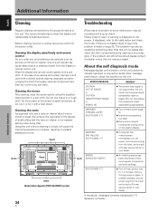
...and then dry it with a soft cloth. If problem persists, remove power plug from its outlet and consult a Pioneer service center or your dealer. Cleaning the display panel body and remote control Do not under any objects blocking the ...as benzine or thinner for 1-2 minutes, then try turning power on pages 38 to clean the display and related parts is listed on the screen. ERROR MESSAGE CAUTION OUT OF RANGE or CAUTION UNSUPPORTED SIGNAL or SIGNAL NG REMEDY ...FAN FAILURE SHUT DOWN (**) ¶ Turn off main power, wait for cleaner. Vents Illustration depicts PDP-504CMX model.
...and then dry it with a soft cloth. If problem persists, remove power plug from its outlet and consult a Pioneer service center or your dealer. Cleaning the display panel body and remote control Do not under any objects blocking the ...as benzine or thinner for 1-2 minutes, then try turning power on pages 38 to clean the display and related parts is listed on the screen. ERROR MESSAGE CAUTION OUT OF RANGE or CAUTION UNSUPPORTED SIGNAL or SIGNAL NG REMEDY ...FAN FAILURE SHUT DOWN (**) ¶ Turn off main power, wait for cleaner. Vents Illustration depicts PDP-504CMX model.

Operating Instructions
Page 41
... the menu screen (page 27). In this unit may cause picture distortion and similar problems. • Normal sound of the cooling fan and internal sliding parts of image appear to operate only after ambient temperature exceeds 35°C (differs depending on ? (page 9) • External influences such as picture size made correctly...
... the menu screen (page 27). In this unit may cause picture distortion and similar problems. • Normal sound of the cooling fan and internal sliding parts of image appear to operate only after ambient temperature exceeds 35°C (differs depending on ? (page 9) • External influences such as picture size made correctly...
Operating Instructions
Page 42
... installation technician, the green indicator may occur in a high-precision array, but it is continuously displayed. STANDBY and ON indicators During operation of internal electronic parts, or other than the above 40 °C. If the problem persists, disconnect the power plug and consult your dealer or a service center. The display should...
... installation technician, the green indicator may occur in a high-precision array, but it is continuously displayed. STANDBY and ON indicators During operation of internal electronic parts, or other than the above 40 °C. If the problem persists, disconnect the power plug and consult your dealer or a service center. The display should...


