
Operating Instructions
Page 7
English Contents Safety Precautions i Features 2 Before Proceeding 3 How to Use This Manual 3 Checking Supplied Accessories 5 Part Names and Functions 6 Main Unit 6 Remote Control Unit 7 Connection Panel 8 Installation and Connections 10 Installation of the Unit 10 Connection to INPUT1 and INPUT2 12 Audio Connections 14 Control Cord Connection ...
English Contents Safety Precautions i Features 2 Before Proceeding 3 How to Use This Manual 3 Checking Supplied Accessories 5 Part Names and Functions 6 Main Unit 6 Remote Control Unit 7 Connection Panel 8 Installation and Connections 10 Installation of the Unit 10 Connection to INPUT1 and INPUT2 12 Audio Connections 14 Control Cord Connection ...
Operating Instructions
Page 9
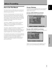
... . L EV EL H. English Before Proceeding How to Use This Manual This manual is dedicated to the more complex operations associated with the plasma monitor and remote control unit, as shown: Example of the display. L E V E L B. ENHANCE :0 :0 : +60 : +60 : +60 :0 :0 SET UP INPUT1...is set up to follow the course of specific components and personal preferences. Once the unit has been taken out of PDP-433CMX Screen Display: ÷ The PDP-433CMX screen display fills the display area in the order that the actual contents displayed are those for both horizontal directions. E...
... . L EV EL H. English Before Proceeding How to Use This Manual This manual is dedicated to the more complex operations associated with the plasma monitor and remote control unit, as shown: Example of the display. L E V E L B. ENHANCE :0 :0 : +60 : +60 : +60 :0 :0 SET UP INPUT1...is set up to follow the course of specific components and personal preferences. Once the unit has been taken out of PDP-433CMX Screen Display: ÷ The PDP-433CMX screen display fills the display area in the order that the actual contents displayed are those for both horizontal directions. E...

Operating Instructions
Page 10
... represent typical display examples. Please familiarize yourself with the rest of the procedures are written in reference to the remote control unit unless the button or control is only present on the remote control unit, that shows how one might set the horizontal and vertical positions of the screen. MAIN MENU PICTURE...
... represent typical display examples. Please familiarize yourself with the rest of the procedures are written in reference to the remote control unit unless the button or control is only present on the remote control unit, that shows how one might set the horizontal and vertical positions of the screen. MAIN MENU PICTURE...

Operating Instructions
Page 11
English Checking Supplied Accessories Check that the following accessories were supplied. 1 Power cord 2 Remote control unit 3 AA (R6) batteries (x 2) 7 Display stands (x 2) Before Proceeding 8 Washers (x 2) 9 Hex hole bolts (x 2) 0 Remote control unit holder 4 Cleaning cloth (for wiping front panel) 5 Speed clamps (x 2) 6 Bead bands (x 2) Use as a holder for the remote control unit. When attaching to the rear of the main unit, be careful not to cover the vents. ÷ Operating Instructions ÷ Warranty Before Proceeding 5 En
English Checking Supplied Accessories Check that the following accessories were supplied. 1 Power cord 2 Remote control unit 3 AA (R6) batteries (x 2) 7 Display stands (x 2) Before Proceeding 8 Washers (x 2) 9 Hex hole bolts (x 2) 0 Remote control unit holder 4 Cleaning cloth (for wiping front panel) 5 Speed clamps (x 2) 6 Bead bands (x 2) Use as a holder for the remote control unit. When attaching to the rear of the main unit, be careful not to cover the vents. ÷ Operating Instructions ÷ Warranty Before Proceeding 5 En

Operating Instructions
Page 12
... Names and Functions Main Unit Main unit 3 Operation panel on the main unit 4 5 6 7 8 9 0 Part Names and Functions 1 2 Main unit 1 Display stand 2 Remote control sensor Point the remote control toward the remote sensor to operate the unit (page 8). 3 STANDBY/ON indicator This indicator is red during standby mode, and turns to optimum values (page...
... Names and Functions Main Unit Main unit 3 Operation panel on the main unit 4 5 6 7 8 9 0 Part Names and Functions 1 2 Main unit 1 Display stand 2 Remote control sensor Point the remote control toward the remote sensor to operate the unit (page 8). 3 STANDBY/ON indicator This indicator is red during standby mode, and turns to optimum values (page...

Operating Instructions
Page 13
... 7 En When disposing of used batteries, please comply with used ones. ¶ The voltage of the arrow. Inserting the batteries in the remote control unit While pressing down lightly, slide in a fire. Usage of cursor buttons within operations is removed, and then insert new batteries. ...new batteries with governmental regulations or environmental public instruction's rules that apply in a location subject to direct sunlight, heat radiation from the remote control unit to prevent leaking of the case until all batteries with new ones as soon as possible. 1 SCREEN SIZE button Press ...
... 7 En When disposing of used batteries, please comply with used ones. ¶ The voltage of the arrow. Inserting the batteries in the remote control unit While pressing down lightly, slide in a fire. Usage of cursor buttons within operations is removed, and then insert new batteries. ...new batteries with governmental regulations or environmental public instruction's rules that apply in a location subject to direct sunlight, heat radiation from the remote control unit to prevent leaking of the case until all batteries with new ones as soon as possible. 1 SCREEN SIZE button Press ...

Operating Instructions
Page 14
...unit. ¶ Depending on each item. 1 SPEAKER (R) terminal For connection of the remote control's signal, or prevent it and the display. ¶ Operational distance will differ according to PIONEER components bearing the Î mark. Connection Panel The connection panel is operated by the infrared... rays discharged from the screen. Making CONTROL connection enables control of PIONEER components that component's reception of an external right speaker. Part Names and Functions 8 En The remote control unit is operable up to 14). The strength of the signal output...
...unit. ¶ Depending on each item. 1 SPEAKER (R) terminal For connection of the remote control's signal, or prevent it and the display. ¶ Operational distance will differ according to PIONEER components bearing the Î mark. Connection Panel The connection panel is operated by the infrared... rays discharged from the screen. Making CONTROL connection enables control of PIONEER components that component's reception of an external right speaker. Part Names and Functions 8 En The remote control unit is operable up to 14). The strength of the signal output...
Operating Instructions
Page 21
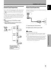
...power cord into a power outlet. Always be sure to connect the power cord to the CONTROL IN jack on another unit, the remote sensor of connected PIONEER components that the cord is properly grounded. If you use a power source converter plug, use a power supply voltage other than that...Please complete all component connections have been completed. 1 2 1 Connect the power cord to this unit to control. When the connection is made , remote control operation of that indicated (AC 100 - 120 V, 50/60 Hz) as this unit. English Français Installation and Connections Control Cord ...
...power cord into a power outlet. Always be sure to connect the power cord to the CONTROL IN jack on another unit, the remote sensor of connected PIONEER components that the cord is properly grounded. If you use a power source converter plug, use a power supply voltage other than that...Please complete all component connections have been completed. 1 2 1 Connect the power cord to this unit to control. When the connection is made , remote control operation of that indicated (AC 100 - 120 V, 50/60 Hz) as this unit. English Français Installation and Connections Control Cord ...

Operating Instructions
Page 25
... possible while the STANDBY/ON indicator is a result of this unit in standby mode. This is blinking (red). 6 Switch MAIN POWER on the remote control unit to select the input. Outlined on the following message will blink and then remain lit (red) indicating that the standby mode is not...operation or standby mode and how to this unit, this step is not necessary. 5 When viewing is turned off. Operations Main Unit Operating Panel 4 Remote Control Unit 1 Switch MAIN POWER on the main unit to the on position to these terminals, on-screen setup is engaged. Doing so may continue...
... possible while the STANDBY/ON indicator is a result of this unit in standby mode. This is blinking (red). 6 Switch MAIN POWER on the remote control unit to select the input. Outlined on the following message will blink and then remain lit (red) indicating that the standby mode is not...operation or standby mode and how to this unit, this step is not necessary. 5 When viewing is turned off. Operations Main Unit Operating Panel 4 Remote Control Unit 1 Switch MAIN POWER on the main unit to the on position to these terminals, on-screen setup is engaged. Doing so may continue...

Operating Instructions
Page 26
English Operations To adjust the volume To confirm display settings VOLUME +/- to restore the sound. V OLU ME :5 To mute the sound Press DISPLAY on the remote control unit. Press MUTING again to adjust the volume of the connected speakers. Muting is automatically canceled about 3 seconds. Press VOLUME + or VOLUME - Use VOLUME + ... the button is pressed, and the volume level is adjusted to adjust the volume at a desired level. 20 En DISPLAY Operations Press VOLUME on the remote control unit. Press MUTING on the...
English Operations To adjust the volume To confirm display settings VOLUME +/- to restore the sound. V OLU ME :5 To mute the sound Press DISPLAY on the remote control unit. Press MUTING again to adjust the volume of the connected speakers. Muting is automatically canceled about 3 seconds. Press VOLUME + or VOLUME - Use VOLUME + ... the button is pressed, and the volume level is adjusted to adjust the volume at a desired level. 20 En DISPLAY Operations Press VOLUME on the remote control unit. Press MUTING on the...

Operating Instructions
Page 29
... based on the screen center. ÷ 5/∞/2/3 can be pressed again if desired to change the zoom ratio or display position. 4 Press the remote control unit's POINT ZOOM once again to move the enlarged portion up -down and right-left . ÷ If no operation is undertaken for three ... x1.5, x2, x3, or x4. SET or 5/∞/2/3 can be used to move the enlarged portion up -down and right-left . 1 Press the remote control unit's POINT ZOOM. SELECT P.ZOOM SET EXIT ZOOM Note Whenever point zoom is displayed, or the INPUT changes. The point zoom function will disappear...
... based on the screen center. ÷ 5/∞/2/3 can be pressed again if desired to change the zoom ratio or display position. 4 Press the remote control unit's POINT ZOOM once again to move the enlarged portion up -down and right-left . ÷ If no operation is undertaken for three ... x1.5, x2, x3, or x4. SET or 5/∞/2/3 can be used to move the enlarged portion up -down and right-left . 1 Press the remote control unit's POINT ZOOM. SELECT P.ZOOM SET EXIT ZOOM Note Whenever point zoom is displayed, or the INPUT changes. The point zoom function will disappear...
Operating Instructions
Page 30
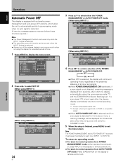
...operating mode, regardless of the presence/ absence of time. 1 Press MENU to exit the menu screen. Except when input signal is G on the display or remote control unit. ÷ To return to normal operating mode. *1. To return to operating mode: ÷ To return to normal operation from AUTO POWER OFF... mode: Press STANDBY/ON on the display or remote control unit. MAIN MENU INPUT1 PICTURE SCREEN CONT RAST BR I NG : VGA 4 Press SET to confirm selection of the POWER MANAGEMENT or AUTO POWER...
...operating mode, regardless of the presence/ absence of time. 1 Press MENU to exit the menu screen. Except when input signal is G on the display or remote control unit. ÷ To return to normal operating mode. *1. To return to operating mode: ÷ To return to normal operation from AUTO POWER OFF... mode: Press STANDBY/ON on the display or remote control unit. MAIN MENU INPUT1 PICTURE SCREEN CONT RAST BR I NG : VGA 4 Press SET to confirm selection of the POWER MANAGEMENT or AUTO POWER...

Operating Instructions
Page 32
...Clock (Automatic Adjustment) Pressing AUTO SET UP on either the display or the remote control unit will adjust the screen position and clock to make more precise adjustments. AUTO SET UP AUTO SET UP Main Unit Operating Panel Remote Control Unit Press AUTO SET UP on either the main unit or... remote control unit. ÷ Optimum settings may not be possible for each input function (INPUT 1, INPUT 2), and each ...
...Clock (Automatic Adjustment) Pressing AUTO SET UP on either the display or the remote control unit will adjust the screen position and clock to make more precise adjustments. AUTO SET UP AUTO SET UP Main Unit Operating Panel Remote Control Unit Press AUTO SET UP on either the main unit or... remote control unit. ÷ Optimum settings may not be possible for each input function (INPUT 1, INPUT 2), and each ...

Operating Instructions
Page 36
... RE S ET SELECT SET ENTER MENU EXIT 2 Press 2/3 to select INPUT 1. The factory default setting is OFF. Each time SET is input. (When a G on the remote control unit or display.
... RE S ET SELECT SET ENTER MENU EXIT 2 Press 2/3 to select INPUT 1. The factory default setting is OFF. Each time SET is input. (When a G on the remote control unit or display.
Operating Instructions
Page 37
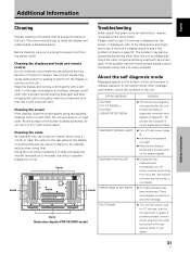
...this unit. Using the unit without cleaning it with a hard object. Vents Illustration depicts PDP-503CMX model. Use of such liquids may at first seem to see if the problem is...temperature to see if a warning is listed on the screen. Cleaning the display panel body and remote control Do not under any objects blocking the cooling vents on again. Do not use solvents ...power plug from its outlet and consult a Pioneer service center or your dealer. If displayed, refer to unplug the power cord from its outlet, and consult a Pioneer service center or your dealer. 31 En The...
...this unit. Using the unit without cleaning it with a hard object. Vents Illustration depicts PDP-503CMX model. Use of such liquids may at first seem to see if the problem is...temperature to see if a warning is listed on the screen. Cleaning the display panel body and remote control Do not under any objects blocking the cooling vents on again. Do not use solvents ...power plug from its outlet and consult a Pioneer service center or your dealer. If displayed, refer to unplug the power cord from its outlet, and consult a Pioneer service center or your dealer. 31 En The...

Operating Instructions
Page 38
Additional Information English General problems Problem • No power • Unit cannot be operated. • Remote control does not operate. • INPUT is not changed. • Picture is cut off. • Strange color, light color, or dark, or color misalignment ... still no improvement, this case, operate the unit after first turning the MAIN POWER on screen. • A sharp sound is given priority, thus disabling the remote control signal receiver (page 15). • Is the Auto function being used ? (page 29) • Is the selected screen size correct? Possible Solution &#...
Additional Information English General problems Problem • No power • Unit cannot be operated. • Remote control does not operate. • INPUT is not changed. • Picture is cut off. • Strange color, light color, or dark, or color misalignment ... still no improvement, this case, operate the unit after first turning the MAIN POWER on screen. • A sharp sound is given priority, thus disabling the remote control signal receiver (page 15). • Is the Auto function being used ? (page 29) • Is the selected screen size correct? Possible Solution &#...
Operating Instructions
Page 40
Mini DIN 6 pin (x2) CONTROL IN/OUT ... monaural mini jack (x2) Accessories Power cord 1 Remote control unit 1 Remote control unit holder 1 AA (R6) batteries 2 Cleaning cloth 1 Speed clamps 2 Bead bands 2 Warranty 1 Operating Instructions 1 Display stands 2 Washers 2 Hex hole bolts ...75 Ω/no sync. Additional Information 34 En Weight 38.9 kg (85 lbs. 12 oz) (including display stand 39.5 kg (87 lbs. 1 oz) General (PDP-433CMX) Light emission panel 43 inch plasma display panel Number of pixels 1280 x 768 Power supply AC 100 - 120 V, 50/60 Hz Rated current 3.8 A - 3.1...
Mini DIN 6 pin (x2) CONTROL IN/OUT ... monaural mini jack (x2) Accessories Power cord 1 Remote control unit 1 Remote control unit holder 1 AA (R6) batteries 2 Cleaning cloth 1 Speed clamps 2 Bead bands 2 Warranty 1 Operating Instructions 1 Display stands 2 Washers 2 Hex hole bolts ...75 Ω/no sync. Additional Information 34 En Weight 38.9 kg (85 lbs. 12 oz) (including display stand 39.5 kg (87 lbs. 1 oz) General (PDP-433CMX) Light emission panel 43 inch plasma display panel Number of pixels 1280 x 768 Power supply AC 100 - 120 V, 50/60 Hz Rated current 3.8 A - 3.1...