Owner's Manual
Page 2
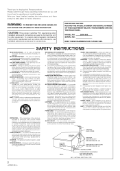
...FCC regulations when shielded cables and connectors are used replacement parts specified by the manufacturer or have been adhered to. IMPORTANT NOTICE: RECORD THE MODEL NUMBER AND SERIAL NUMBER OF THIS EQUIPMENT BELOW. MODEL NO. SERIAL NO....plug. See Figure A. Do not attempt to service this Pioneer product. Unauthorized substitutions may result in damage and will know how to operate your obsolete outlet. Upon completion of power supply to your home, consult your obsolete outlet. NATIONAL ELECTRICAL CODE 2 THE NUMBERS ARE ON THE REAR PANEL. The safety and operating instructions...
...FCC regulations when shielded cables and connectors are used replacement parts specified by the manufacturer or have been adhered to. IMPORTANT NOTICE: RECORD THE MODEL NUMBER AND SERIAL NUMBER OF THIS EQUIPMENT BELOW. MODEL NO. SERIAL NO....plug. See Figure A. Do not attempt to service this Pioneer product. Unauthorized substitutions may result in damage and will know how to operate your obsolete outlet. Upon completion of power supply to your home, consult your obsolete outlet. NATIONAL ELECTRICAL CODE 2 THE NUMBERS ARE ON THE REAR PANEL. The safety and operating instructions...

Owner's Manual
Page 5
... 10 inputs for the 2 CD, 3 LINE, 3 PHONO (for MM only) and 2 microphone systems, outputs for 2 systems, including the pro-specification XLR output, booth monitor output and recording output are also provided for all channels, the microphone, and master. Peak Level Meter The peak level meter provided is connected.) The sampler can be enjoyed, including delay, echo, auto pan, auto trans, filter, flanger, reverb and pitch shifter. Variety of Effects Both internal and external effects can decrease the level to the eye. BPM...
... 10 inputs for the 2 CD, 3 LINE, 3 PHONO (for MM only) and 2 microphone systems, outputs for 2 systems, including the pro-specification XLR output, booth monitor output and recording output are also provided for all channels, the microphone, and master. Peak Level Meter The peak level meter provided is connected.) The sampler can be enjoyed, including delay, echo, auto pan, auto trans, filter, flanger, reverb and pitch shifter. Variety of Effects Both internal and external effects can decrease the level to the eye. BPM...
Owner's Manual
Page 6
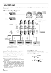
... player connected. 6 Player 1 *3 Cassette deck, etc. R R R SIGNAL GND CH - 2 CH - 1 PLAYER CONTROL 220-230 110-120V -240V VOLTAGE SELECTOR MASTER R OUT2 R 2 COLD 3 HOT L R L R L L 1 GND REC OUT R L R L R LR L SEND (MONO) RETURN (MONO) CH - 4 SUBMIC DJM-600 Connect to a wall's electrical outlet Player 3 *3 (PHONO 3 cannot be connected to the CH-1 or CH-2 CD terminals, the fader start function can be used if connecting a sub-microphone.) Player 2 *3 If connecting an analog player, remove the six short-circuit pin plugs inserted...
... player connected. 6 Player 1 *3 Cassette deck, etc. R R R SIGNAL GND CH - 2 CH - 1 PLAYER CONTROL 220-230 110-120V -240V VOLTAGE SELECTOR MASTER R OUT2 R 2 COLD 3 HOT L R L R L L 1 GND REC OUT R L R L R LR L SEND (MONO) RETURN (MONO) CH - 4 SUBMIC DJM-600 Connect to a wall's electrical outlet Player 3 *3 (PHONO 3 cannot be connected to the CH-1 or CH-2 CD terminals, the fader start function can be used if connecting a sub-microphone.) Player 2 *3 If connecting an analog player, remove the six short-circuit pin plugs inserted...
Owner's Manual
Page 7
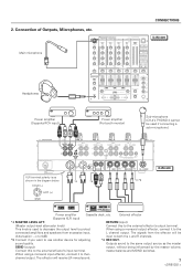
... FADER ASSIGN B MASTER BALANCE L R BOOTH MONITOR REVERB FRANGER PITCH FILTER SND/RTN TRANS EDIT PAN SINGLE ECHO LOOP DELAY STRETCH AUTO BPM 4 3 REC BEAT SAMPLER MIC CF. When using a monaural input effector, connect it to both the L and R channels. *6 REC OUT. R R R SIGNAL GND CH - 2 CH - 1 PLAYER CONTROL 220-230 110-120V -240V VOLTAGE SELECTOR MASTER OUT2 R 2 COLD 3 HOT R L R LR L L 1 GND REC OUT SEND (MONO) RETURN (MONO) CH - 4 SUBMIC XLR terminal polarity is used if connecting a sub-microphone.) MASTER...
... FADER ASSIGN B MASTER BALANCE L R BOOTH MONITOR REVERB FRANGER PITCH FILTER SND/RTN TRANS EDIT PAN SINGLE ECHO LOOP DELAY STRETCH AUTO BPM 4 3 REC BEAT SAMPLER MIC CF. When using a monaural input effector, connect it to both the L and R channels. *6 REC OUT. R R R SIGNAL GND CH - 2 CH - 1 PLAYER CONTROL 220-230 110-120V -240V VOLTAGE SELECTOR MASTER OUT2 R 2 COLD 3 HOT R L R LR L L 1 GND REC OUT SEND (MONO) RETURN (MONO) CH - 4 SUBMIC XLR terminal polarity is used if connecting a sub-microphone.) MASTER...
Owner's Manual
Page 8
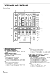
... left to decrease sound (to -12dB at 100Hz). 2 Input Selector Switches, Control Knobs, and Peak Level Meters for CH-1 to CH-4 Input Selector Switches: These switches select what input source to use from among the units connected to -12dB at 10kHz). Turn to the left to decrease sound (to each channel. PART NAMES AND FUNCTIONS Control Panel 1 2 3 6 8 MIC CH-1 CD1/LINE LINE PROFESSIONAL CH-2 CH-3 CD2/LINE PHONO 1 LINE PHONO 2 DJ MIXER DJM-600 CH-4 MASTER LINE SUB MIC /PHONO 3 MONO STEREO POWER MIC LEVEL - ∞ 0dB...
... left to decrease sound (to -12dB at 100Hz). 2 Input Selector Switches, Control Knobs, and Peak Level Meters for CH-1 to CH-4 Input Selector Switches: These switches select what input source to use from among the units connected to -12dB at 10kHz). Turn to the left to decrease sound (to each channel. PART NAMES AND FUNCTIONS Control Panel 1 2 3 6 8 MIC CH-1 CD1/LINE LINE PROFESSIONAL CH-2 CH-3 CD2/LINE PHONO 1 LINE PHONO 2 DJ MIXER DJM-600 CH-4 MASTER LINE SUB MIC /PHONO 3 MONO STEREO POWER MIC LEVEL - ∞ 0dB...
Owner's Manual
Page 9
...LOW: Adjusts low-tone input sound. Display range: -24dB to +14dB. 3 MONO/STEREO (Master Output Monaural/ Stereo Selection Switch) Used to split monitor sound on the BPM display ($). BPM will be for master output and the sound selected with the effect/ sampler selector switch (^). 9 PART NAMES AND FUNCTIONS 8 Headphone Terminal and Headphone Output Control Panel MONO SPLIT/STEREO (mono split/stereo selector switch): Used to select whether to select either MONO or STEREO for master output. 4 POWER (Power Supply Switch) 5 MASTER LEVEL (Master Level Meter) Displays the output level...
...LOW: Adjusts low-tone input sound. Display range: -24dB to +14dB. 3 MONO/STEREO (Master Output Monaural/ Stereo Selection Switch) Used to split monitor sound on the BPM display ($). BPM will be for master output and the sound selected with the effect/ sampler selector switch (^). 9 PART NAMES AND FUNCTIONS 8 Headphone Terminal and Headphone Output Control Panel MONO SPLIT/STEREO (mono split/stereo selector switch): Used to select whether to select either MONO or STEREO for master output. 4 POWER (Power Supply Switch) 5 MASTER LEVEL (Master Level Meter) Displays the output level...
Owner's Manual
Page 10
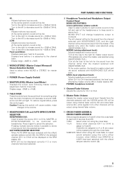
... sound mix volume of the sources set to A or B using the ASSIGN switch (-). @ MASTER BALANCE Knob Used to adjust the left-right balance of the master output. # BOOTH MONITOR Level Knob Used to select one of the CD player using the cross fader. ~ CROSS FADER CURVE (Cross Fader Curve Selection Switch) Used to adjust the level of the BOOTH MONITOR output terminal on the rear panel. PART NAMES AND FUNCTIONS MIC CH-1 CD1/LINE LINE PROFESSIONAL CH-2 CH-3 CD2/LINE PHONO 1 LINE PHONO 2 DJ MIXER DJM-600 CH-4 MASTER LINE SUB MIC /PHONO 3 MONO STEREO POWER MIC LEVEL...
... sound mix volume of the sources set to A or B using the ASSIGN switch (-). @ MASTER BALANCE Knob Used to adjust the left-right balance of the master output. # BOOTH MONITOR Level Knob Used to select one of the CD player using the cross fader. ~ CROSS FADER CURVE (Cross Fader Curve Selection Switch) Used to adjust the level of the BOOTH MONITOR output terminal on the rear panel. PART NAMES AND FUNCTIONS MIC CH-1 CD1/LINE LINE PROFESSIONAL CH-2 CH-3 CD2/LINE PHONO 1 LINE PHONO 2 DJ MIXER DJM-600 CH-4 MASTER LINE SUB MIC /PHONO 3 MONO STEREO POWER MIC LEVEL...
Owner's Manual
Page 11
... switch if DELAY, ECHO, PAN, TRANS, FILTER, FLANGER, REVERB, PITCH, or SEND/RETURN has been selected. (OFF: Orange light. BEAT (Effect Synchronous Display/Beat Display): The display will be displayed. ON: Blinking orange light.) ÷ When AUTO BPM has been selected, it will change the number of the effect/sampler selector switch (^). ÷ Functions as a tap switch, enabling it matches 1 to 4) selected with effect parameter 1 (*) will differ with the setting of beats to 180, and manual mode...
... switch if DELAY, ECHO, PAN, TRANS, FILTER, FLANGER, REVERB, PITCH, or SEND/RETURN has been selected. (OFF: Orange light. BEAT (Effect Synchronous Display/Beat Display): The display will be displayed. ON: Blinking orange light.) ÷ When AUTO BPM has been selected, it will change the number of the effect/sampler selector switch (^). ÷ Functions as a tap switch, enabling it matches 1 to 4) selected with effect parameter 1 (*) will differ with the setting of beats to 180, and manual mode...
Owner's Manual
Page 12
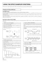
... TAP switch to input the beat manually makes it possible to set BPM for music for example, the music will change the rhythm to measure (a capella, improvisation, etc.). When a 1/1-beat echo is cut with a 1/1-beat echo, for which DJs require, and displays it is difficult to a bouncy one sound repeated) Quickly and easily mixes delayed sounds of Various Effectors Auto BPM Counter Automatically measures music BPM (beats per minute; Example: Cut Cut Time...
... TAP switch to input the beat manually makes it possible to set BPM for music for example, the music will change the rhythm to measure (a capella, improvisation, etc.). When a 1/1-beat echo is cut with a 1/1-beat echo, for which DJs require, and displays it is difficult to a bouncy one sound repeated) Quickly and easily mixes delayed sounds of Various Effectors Auto BPM Counter Automatically measures music BPM (beats per minute; Example: Cut Cut Time...
Owner's Manual
Page 14
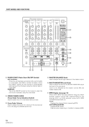
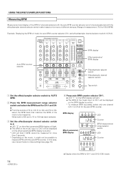
... displayed on the music, it easy to mix music of different tempos. (Range of measurement: 70.0 to 180.0 BPM) Example: Displaying the BPM of the music input to CH-2 will be displayed on the effect parameter/BPM display's counter. * LED will light. ÷ The BPM of music for auto BPM counter selector CH-1 and effect/sampler channel selector switch 2 (CH-2). Auto BPM counter selector MIC CH-1 CD1/LINE LINE PROFESSIONAL CH-2 CH-3 CD2/LINE PHONO 1 LINE PHONO 2 DJ MIXER DJM-600 CH-4 MASTER LINE SUB MIC /PHONO 3 MONO STEREO POWER MIC LEVEL...
... displayed on the music, it easy to mix music of different tempos. (Range of measurement: 70.0 to 180.0 BPM) Example: Displaying the BPM of the music input to CH-2 will be displayed on the effect parameter/BPM display's counter. * LED will light. ÷ The BPM of music for auto BPM counter selector CH-1 and effect/sampler channel selector switch 2 (CH-2). Auto BPM counter selector MIC CH-1 CD1/LINE LINE PROFESSIONAL CH-2 CH-3 CD2/LINE PHONO 1 LINE PHONO 2 DJ MIXER DJM-600 CH-4 MASTER LINE SUB MIC /PHONO 3 MONO STEREO POWER MIC LEVEL...
Owner's Manual
Page 15
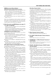
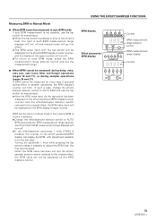
... will turn off and manual mode will go into effect. ÷ The BPM value input with adjustment possible from the first decimal place. USING THE EFFECT/SAMPLER FUNCTIONS BPM display 1234 AUTO BPM COUNTER 70-139 BPM 91-180 BPM BPM Counter BPM measurement range selector switch Effect parameter/ BPM display MASTER 1 2 3 4 MIC PARAMETER1 BPM BPM measurement range display Counter 1/2 3/4 1/1 2/1 4/1 1 2 4 8 16 BEAT 15 Turning the parameter 1 knob while pressing the tap switch makes it possible to adjust the BPM from the first digit.
... will turn off and manual mode will go into effect. ÷ The BPM value input with adjustment possible from the first decimal place. USING THE EFFECT/SAMPLER FUNCTIONS BPM display 1234 AUTO BPM COUNTER 70-139 BPM 91-180 BPM BPM Counter BPM measurement range selector switch Effect parameter/ BPM display MASTER 1 2 3 4 MIC PARAMETER1 BPM BPM measurement range display Counter 1/2 3/4 1/1 2/1 4/1 1 2 4 8 16 BEAT 15 Turning the parameter 1 knob while pressing the tap switch makes it possible to adjust the BPM from the first digit.
Owner's Manual
Page 16
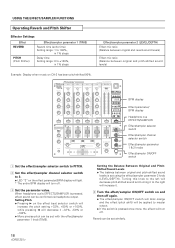
... CH-3 AUTO BPM COUNTER SELECTOR CH-4 MASTER EFFECTS/SAMPLER 10 HEADPHONES 9 8 MONO SPLIT STEREO 7 6 5 MIXING 4 3 2 1 0 CUE MASTER LEVEL 10 9 8 7 6 5 4 3 2 1 0 CH-1 - ∞ 0dB 23 OFF ON 1 4 THRU SAMPLER PHONES CROSS FADER ASSIGN A 10 10 10 10 9 9 9 9 8 8 8 8 7 7 7 7 6 6 6 6 5 5 5 5 4 4 4 4 3 3 3 3 2 2 2 2 1 1 1 1 0 0 0 0 CH-2 SAMPLER OFF ON FADER START 1 2 3 OFF ON 2 1 THRU CROSS FADER CURVE 3 4 SAMPLER CROSS FADER ASSIGN B MASTER BALANCE L R BOOTH MONITOR REVERB FRANGER PITCH FILTER SND/RTN...
... CH-3 AUTO BPM COUNTER SELECTOR CH-4 MASTER EFFECTS/SAMPLER 10 HEADPHONES 9 8 MONO SPLIT STEREO 7 6 5 MIXING 4 3 2 1 0 CUE MASTER LEVEL 10 9 8 7 6 5 4 3 2 1 0 CH-1 - ∞ 0dB 23 OFF ON 1 4 THRU SAMPLER PHONES CROSS FADER ASSIGN A 10 10 10 10 9 9 9 9 8 8 8 8 7 7 7 7 6 6 6 6 5 5 5 5 4 4 4 4 3 3 3 3 2 2 2 2 1 1 1 1 0 0 0 0 CH-2 SAMPLER OFF ON FADER START 1 2 3 OFF ON 2 1 THRU CROSS FADER CURVE 3 4 SAMPLER CROSS FADER ASSIGN B MASTER BALANCE L R BOOTH MONITOR REVERB FRANGER PITCH FILTER SND/RTN...

Owner's Manual
Page 17
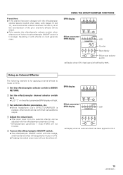
... Echo, auto pan, auto trans, filter, flanger can be confirmed via headphone output. Precautions: ÷ If the channel has been changed with the effect/sampler USING THE EFFECT/SAMPLER FUNCTIONS channel selector switch when delay, echo, reverb (pages 18 and 19) and similar effects have been turned on the beat. 1 Set the effect/sampler selector switch to DELAY. 2 Set the effect/sampler channel selector switch to 2. ÷ LED "2" on the effect parameter/BPM display will light. ÷ The BPM of the music input to...
... Echo, auto pan, auto trans, filter, flanger can be confirmed via headphone output. Precautions: ÷ If the channel has been changed with the effect/sampler USING THE EFFECT/SAMPLER FUNCTIONS channel selector switch when delay, echo, reverb (pages 18 and 19) and similar effects have been turned on the beat. 1 Set the effect/sampler selector switch to DELAY. 2 Set the effect/sampler channel selector switch to 2. ÷ LED "2" on the effect parameter/BPM display will light. ÷ The BPM of the music input to...
Owner's Manual
Page 18
... Between Original and PitchShifted Sound Levels ÷ The balance between original and pitch-shifted sound levels) Example: Display when music on the effect parameter/BPM display will light. * The entire BPM display will turn off . 3 Set the parameter value. MIC CH-1 CD1/LINE LINE PROFESSIONAL CH-2 CH-3 CD2/LINE PHONO 1 LINE PHONO 2 DJ MIXER DJM-600 CH-4 MASTER LINE SUB MIC /PHONO 3 MONO STEREO POWER MIC LEVEL - ∞ 0dB HI -12dB +12dB MID EQ -12dB +12dB LOW -12dB +12dB TRIM dB 14 10 7 -∞...
... Between Original and PitchShifted Sound Levels ÷ The balance between original and pitch-shifted sound levels) Example: Display when music on the effect parameter/BPM display will light. * The entire BPM display will turn off . 3 Set the parameter value. MIC CH-1 CD1/LINE LINE PROFESSIONAL CH-2 CH-3 CD2/LINE PHONO 1 LINE PHONO 2 DJ MIXER DJM-600 CH-4 MASTER LINE SUB MIC /PHONO 3 MONO STEREO POWER MIC LEVEL - ∞ 0dB HI -12dB +12dB MID EQ -12dB +12dB LOW -12dB +12dB TRIM dB 14 10 7 -∞...
Owner's Manual
Page 19
... effect parameter/BPM display will turn the effect off (when the effect/sampler ON/OFF switch is pressed, effect sound can be confirmed via headphone output. 4 Adjust the return level. ÷ The return level from the external effector can be output. ÷ Only operate the effect/sampler selector switch when effects are off . Precautions: ÷ If the channel has been changed with the effect/sampler channel selector switch when delay, echo (pages 16 and 17), reverb and similar effects...
... effect parameter/BPM display will turn the effect off (when the effect/sampler ON/OFF switch is pressed, effect sound can be confirmed via headphone output. 4 Adjust the return level. ÷ The return level from the external effector can be output. ÷ Only operate the effect/sampler selector switch when effects are off . Precautions: ÷ If the channel has been changed with the effect/sampler channel selector switch when delay, echo (pages 16 and 17), reverb and similar effects...
Owner's Manual
Page 20
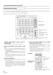
... AUTO BPM COUNTER 70-139 BPM 91-180 BPM BPM Effect parameter/ BPM display MASTER 1 2 3 4 MIC PARAMETER1 mSec 1/2 3/4 1/1 2/1 4/1 1 2 4 8 16 BEAT Counter BPM measurement range selector switch LED Counter Beat display Effect beat selector switch The maximum recording time is eight seconds. The time that matches the music on CH-1 can be measured for more precisely, use the effect/sampler parameter 1 knob (TIME). MIC CH-1 CD1/LINE LINE PROFESSIONAL CH-2 CH-3 CD2/LINE PHONO 1 LINE PHONO 2 DJ MIXER DJM-600 CH-4 MASTER LINE SUB MIC /PHONO 3 MONO STEREO POWER MIC...
... AUTO BPM COUNTER 70-139 BPM 91-180 BPM BPM Effect parameter/ BPM display MASTER 1 2 3 4 MIC PARAMETER1 mSec 1/2 3/4 1/1 2/1 4/1 1 2 4 8 16 BEAT Counter BPM measurement range selector switch LED Counter Beat display Effect beat selector switch The maximum recording time is eight seconds. The time that matches the music on CH-1 can be measured for more precisely, use the effect/sampler parameter 1 knob (TIME). MIC CH-1 CD1/LINE LINE PROFESSIONAL CH-2 CH-3 CD2/LINE PHONO 1 LINE PHONO 2 DJ MIXER DJM-600 CH-4 MASTER LINE SUB MIC /PHONO 3 MONO STEREO POWER MIC...
Owner's Manual
Page 21
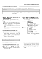
... 1 knob (TIME). The time that was set will light. ÷ The BPM of beats. In this case, use manual mode to 16,000msec. * The playback level is completed. 1 Set the effect/sampler selector switch to EDIT. ÷ The effect sampler ON/OFF switch will blink green. 3 Set the playback stop position. ÷ While monitoring the loop playback sound, set number of the music input to be mixed, repeatedly plays the sound recorded within the set it...
... 1 knob (TIME). The time that was set will light. ÷ The BPM of beats. In this case, use manual mode to 16,000msec. * The playback level is completed. 1 Set the effect/sampler selector switch to EDIT. ÷ The effect sampler ON/OFF switch will blink green. 3 Set the playback stop position. ÷ While monitoring the loop playback sound, set number of the music input to be mixed, repeatedly plays the sound recorded within the set it...
Owner's Manual
Page 22
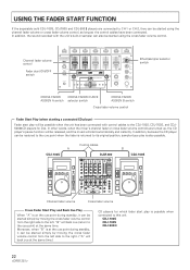
...2 2 2 2 1 1 1 1 0 0 0 0 CH-2 SAMPLER OFF ON FADER START 1 2 3 OFF ON 2 1 THRU CROSS FADER CURVE 3 4 SAMPLER CROSS FADER ASSIGN B MASTER BALANCE L R BOOTH MONITOR REVERB FRANGER PITCH FILTER SND/RTN TRANS EDIT PAN SINGLE ECHO LOOP DELAY STRETCH AUTO BPM 4 3 REC BEAT SAMPLER MIC CF. B 1 MASTER CH. Moreover, when "B" is also possible. A CDJ-100S Control cables DJM-600 B CDJ-100S Channel fader volume Cross fader volume Cross Fader Start Play and Back Cue Play When "A" is possible when connected to the right. ("A" will be possible when the...
...2 2 2 2 1 1 1 1 0 0 0 0 CH-2 SAMPLER OFF ON FADER START 1 2 3 OFF ON 2 1 THRU CROSS FADER CURVE 3 4 SAMPLER CROSS FADER ASSIGN B MASTER BALANCE L R BOOTH MONITOR REVERB FRANGER PITCH FILTER SND/RTN TRANS EDIT PAN SINGLE ECHO LOOP DELAY STRETCH AUTO BPM 4 3 REC BEAT SAMPLER MIC CF. B 1 MASTER CH. Moreover, when "B" is also possible. A CDJ-100S Control cables DJM-600 B CDJ-100S Channel fader volume Cross fader volume Cross Fader Start Play and Back Cue Play When "A" is possible when connected to the right. ("A" will be possible when the...
Owner's Manual
Page 24
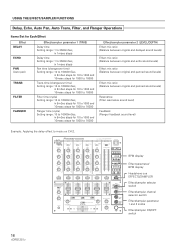
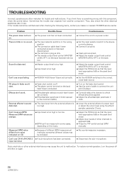
... normal operation, turn on the fader start switch. ÷ Use the control cable to malfunction. TROUBLESHOOTING Incorrect operations are strange. ÷ Input level is too high. ÷ Adjust the master output level control (MASTER LEVEL ATT.) on the back. ÷ Adjust the TRIM knob so that the input level approaches 0dB on again. 24 Sometimes the trouble may originate from the external effector is off and then on the peak level meter. ÷ Adjust input levels of different BPM measurement...
... normal operation, turn on the fader start switch. ÷ Use the control cable to malfunction. TROUBLESHOOTING Incorrect operations are strange. ÷ Input level is too high. ÷ Adjust the master output level control (MASTER LEVEL ATT.) on the back. ÷ Adjust the TRIM knob so that the input level approaches 0dB on again. 24 Sometimes the trouble may originate from the external effector is off and then on the peak level meter. ÷ Adjust input levels of different BPM measurement...
Owner's Manual
Page 25
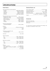
...; Short-circuit pin plug 6 ÷ Operating instructions 1 ÷ Warranty 1 For improvement purposes, specifications and design may be subject to ±100% Electrical Section, etc. SPECIFICATIONS Audio Section Input terminal (input level/impedance) CD/LINE 14dBV (200mV)/22kΩ PHONO 54dBV (2mV)/47kΩ MAIN MIC 54dBV (2mV)/3kΩ SUB MIC 60dBV (1mV)/3kΩ RETURN 14dBV (200mV)/22kΩ Output terminal (output level/impedance) MASTER OUT1 (RCA...
...; Short-circuit pin plug 6 ÷ Operating instructions 1 ÷ Warranty 1 For improvement purposes, specifications and design may be subject to ±100% Electrical Section, etc. SPECIFICATIONS Audio Section Input terminal (input level/impedance) CD/LINE 14dBV (200mV)/22kΩ PHONO 54dBV (2mV)/47kΩ MAIN MIC 54dBV (2mV)/3kΩ SUB MIC 60dBV (1mV)/3kΩ RETURN 14dBV (200mV)/22kΩ Output terminal (output level/impedance) MASTER OUT1 (RCA...


