
Owner's Manual
Page 1
... instructions, put them away in a safe place for connections. Connection of Outputs, Microphones, Etc. ....... 7 NAME AND FUNCTION OF PARTS 8 Front section 8 Rear section 11 USING THE EFFECT FUNCTION 12 Features of Input Equipment 6 2. SERIAL NO. CONTENTS CAUTIONS REGARDING HANDLING 4 Location 4 Condensation 4 Cleaning the unit 4 CHECKING ACCESSORIES 4 FEATURES 5 CONNECTIONS 6 1. Connection of Various Effectors 12 Measuring BPM 14 Operating Delay, Echo, Auto pan, Flanger .......... 15 Operating Pitch Shifter and Reverb 16 Using the External Effecter 16 USING THE FADER...
... instructions, put them away in a safe place for connections. Connection of Outputs, Microphones, Etc. ....... 7 NAME AND FUNCTION OF PARTS 8 Front section 8 Rear section 11 USING THE EFFECT FUNCTION 12 Features of Input Equipment 6 2. SERIAL NO. CONTENTS CAUTIONS REGARDING HANDLING 4 Location 4 Condensation 4 Cleaning the unit 4 CHECKING ACCESSORIES 4 FEATURES 5 CONNECTIONS 6 1. Connection of Various Effectors 12 Measuring BPM 14 Operating Delay, Echo, Auto pan, Flanger .......... 15 Operating Pitch Shifter and Reverb 16 Using the External Effecter 16 USING THE FADER...
Owner's Manual
Page 2
NO USER-SERVICEABLE PARTS INSIDE. HEED WARNING - The appliance should be connected to a power supply only of the type described in the operating instructions or as radiators, heat registers, stoves, or other appliances (including amplifiers) that produce heat. VENTILATION - The appliance should be taken so that may be sure the antenna system is grounded so as a bookcase or cabinet that...
NO USER-SERVICEABLE PARTS INSIDE. HEED WARNING - The appliance should be connected to a power supply only of the type described in the operating instructions or as radiators, heat registers, stoves, or other appliances (including amplifiers) that produce heat. VENTILATION - The appliance should be taken so that may be sure the antenna system is grounded so as a bookcase or cabinet that...
Owner's Manual
Page 3
... B digital device, pursuant to radio communications. This list of the FCC Rules. Over time your volume control at two feet. If this by playing it at a safe level BEFORE your equipment offers. Now it there. After all, we want you avoid prolonged exposure to excessive noise. These limits are designed to consider how you have established a comfortable sound level: ÷ Set...
... B digital device, pursuant to radio communications. This list of the FCC Rules. Over time your volume control at two feet. If this by playing it at a safe level BEFORE your equipment offers. Now it there. After all, we want you avoid prolonged exposure to excessive noise. These limits are designed to consider how you have established a comfortable sound level: ÷ Set...

Owner's Manual
Page 4
... PHONO 1 and PHONO 2 terminals at the rear. • Operating instructions 4 Installation of the sun, or near cookers etc., where the unit may be able to wipe off dust and dirt. • When the surfaces are inserted in a malfunction or accident. (Avoid installation near stoves or radiators. Cleaning the unit • Use a polishing cloth to attain its full...
... PHONO 1 and PHONO 2 terminals at the rear. • Operating instructions 4 Installation of the sun, or near cookers etc., where the unit may be able to wipe off dust and dirt. • When the surfaces are inserted in a malfunction or accident. (Avoid installation near stoves or radiators. Cleaning the unit • Use a polishing cloth to attain its full...

Owner's Manual
Page 5
... Pioneer CD player CDJ-500 series is equipped with 15-bit LED indicators for all channels, the microphone, and master. SEND/RETURN terminals are also provided for MM only) systems, and 2 microphone systems, three outputs including the pro-specifications XLR output, and booth monitor output are provided independently. BPM Level Display (Beat meter display) Displays the level of songs to the 9 inputs, 2 CD and 2 LINE systems, 3 PHONO (for the external effectors. 5 The attenuation level also serves as delay, echo, auto...
... Pioneer CD player CDJ-500 series is equipped with 15-bit LED indicators for all channels, the microphone, and master. SEND/RETURN terminals are also provided for MM only) systems, and 2 microphone systems, three outputs including the pro-specifications XLR output, and booth monitor output are provided independently. BPM Level Display (Beat meter display) Displays the level of songs to the 9 inputs, 2 CD and 2 LINE systems, 3 PHONO (for the external effectors. 5 The attenuation level also serves as delay, echo, auto...
Owner's Manual
Page 6
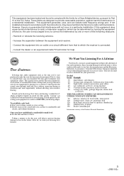
... short-circuit pin plugs serve to cut fine noises to turn off the power switch and disconnect the power cord from the outlet. 1. R SIGNAL GND R CH - 2 CH - 1 PLAYER CONTROL ~AC IN R MASTER OUT 2 R LR LR L CH - 4 L MASTER OUT 3 SEND (MONO) RETURN (MONO) SUBMIC DJM-500 L R L R L R L R L R AC 120V, 60Hz Player 3 Player 2 Player 1 Cassette deck, etc. CONNECTIONS When connecting the units or changing their connections, be connected to CDJ500G and CDJ-500 . CD2 CD1 CDJ-500G/ CDJ-500 Control cord Can be sure to...
... short-circuit pin plugs serve to cut fine noises to turn off the power switch and disconnect the power cord from the outlet. 1. R SIGNAL GND R CH - 2 CH - 1 PLAYER CONTROL ~AC IN R MASTER OUT 2 R LR LR L CH - 4 L MASTER OUT 3 SEND (MONO) RETURN (MONO) SUBMIC DJM-500 L R L R L R L R L R AC 120V, 60Hz Player 3 Player 2 Player 1 Cassette deck, etc. CONNECTIONS When connecting the units or changing their connections, be connected to CDJ500G and CDJ-500 . CD2 CD1 CDJ-500G/ CDJ-500 Control cord Can be sure to...
Owner's Manual
Page 7
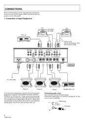
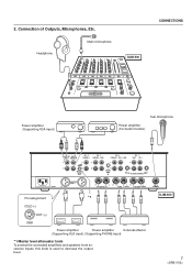
Headphone Main microphone DJM-500 CONNECTIONS Power amplifier (Supporting RCA input) Sub microphone Power amplifier (For booth monitor) R L L R MASTER BOOTH OUT 1 MONITOR L CH - 4 PHONO 3 CH - 3 PHONO 2 LINE L L CH - 2 PHONO 1 CD 2 / LINE CH - 1 LINE CD 1 L L R R R MASTER LEVEL ATT. Connection of Outputs, Microphones, Etc. R SIGNAL GND R CH - 2 CH - 1 PLAYER CONTROL ~AC IN R MASTER OUT 2 R LR LR L CH - 4 L MASTER OUT 3 SEND (MONO) RETURN (MONO) SUBMIC Pin assignment *1 DJM-500 COLD (-) 23 1 HOT (+) GND Power amplifier Power amplifier External...
Headphone Main microphone DJM-500 CONNECTIONS Power amplifier (Supporting RCA input) Sub microphone Power amplifier (For booth monitor) R L L R MASTER BOOTH OUT 1 MONITOR L CH - 4 PHONO 3 CH - 3 PHONO 2 LINE L L CH - 2 PHONO 1 CD 2 / LINE CH - 1 LINE CD 1 L L R R R MASTER LEVEL ATT. Connection of Outputs, Microphones, Etc. R SIGNAL GND R CH - 2 CH - 1 PLAYER CONTROL ~AC IN R MASTER OUT 2 R LR LR L CH - 4 L MASTER OUT 3 SEND (MONO) RETURN (MONO) SUBMIC Pin assignment *1 DJM-500 COLD (-) 23 1 HOT (+) GND Power amplifier Power amplifier External...

Owner's Manual
Page 8
... MASTER 1 2 3 4 MIC PARAMETER % BPM mSec 1/2 3/4 1/1 2/1 4/1 BEAT MIC MONITOR MONO STEREO MONITOR EQ -12dB +12dB MONITOR LEVEL -∞ 0dB CH-1 10 9 8 7 6 5 4 3 2 1 0 CH-2 CH-3 AUTO BPM COUNTER SELECTOR 10 10 9 9 8 8 7 7 6 6 5 5 4 4 3 3 2 2 1 1 0 0 CH-4 10 9 8 7 6 5 4 3 2 1 0 CH-1 CH-2 23 OFF 1 4 ON OFF FADER START ON CROSS FADER OFF ON 23 1 4 PHONES ASSIGN A CROSS FADER ASSIGN B MASTER EFFECT 10 10 EFFECT SELECTOR 9 9 mSec 8 8 7 7 AUTO PAN FLANGER ECHO REVERB 6 6 DELAY PITCH % 5 5 SHIFTER 4 4 AUTO BPM SEND...
... MASTER 1 2 3 4 MIC PARAMETER % BPM mSec 1/2 3/4 1/1 2/1 4/1 BEAT MIC MONITOR MONO STEREO MONITOR EQ -12dB +12dB MONITOR LEVEL -∞ 0dB CH-1 10 9 8 7 6 5 4 3 2 1 0 CH-2 CH-3 AUTO BPM COUNTER SELECTOR 10 10 9 9 8 8 7 7 6 6 5 5 4 4 3 3 2 2 1 1 0 0 CH-4 10 9 8 7 6 5 4 3 2 1 0 CH-1 CH-2 23 OFF 1 4 ON OFF FADER START ON CROSS FADER OFF ON 23 1 4 PHONES ASSIGN A CROSS FADER ASSIGN B MASTER EFFECT 10 10 EFFECT SELECTOR 9 9 mSec 8 8 7 7 AUTO PAN FLANGER ECHO REVERB 6 6 DELAY PITCH % 5 5 SHIFTER 4 4 AUTO BPM SEND...

Owner's Manual
Page 9
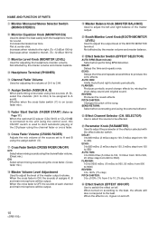
... using the headphone (CH1 to 4, MIC, MASTER, EFFECT). Real-time/average selection button and indicator: (When REAL is turned on . 3 Master Output Monaural/Stereo Selection Switch (MONO/STEREO) NAME AND FUNCTION OF PARTS 4 Master level meter (MASTER LEVEL) Displays the output level after master volume adjusment while holding it for 2 seconds. When more than two are pressed, sounds can be displayed properly. 9 Flat at center click. Counter: Displays the BPM value. 1 Main Microphone Terminal and Microphone Control Knob MIC Level: Used for adjusting the volume of the main...
... using the headphone (CH1 to 4, MIC, MASTER, EFFECT). Real-time/average selection button and indicator: (When REAL is turned on . 3 Master Output Monaural/Stereo Selection Switch (MONO/STEREO) NAME AND FUNCTION OF PARTS 4 Master level meter (MASTER LEVEL) Displays the output level after master volume adjusment while holding it for 2 seconds. When more than two are pressed, sounds can be displayed properly. 9 Flat at center click. Counter: Displays the BPM value. 1 Main Microphone Terminal and Microphone Control Knob MIC Level: Used for adjusting the volume of the main...
Owner's Manual
Page 10
...(MONITOR LEVEL) Used for adjusting the volume of the effector selected with the headphone monitor sound. Effective when the cross fader switch ($) is on (cross fader mix). @ Fader Start Switch (FADER START) (Refer to Page 17.) When the optional CD player (CDJ-500G or CDJ-500 ) is connected to the unit using the cross fader. (Cross fader mix.) % Master Volume Level Adjustment Used to A and B using the assign switch (!). $ Cross Fader Switch (CROSS FADER ON/OFF) OFF: Select when mixing sounds using the channel fader volume. (Direct mix.) ON: Select when mixing sounds using the control cord...
...(MONITOR LEVEL) Used for adjusting the volume of the effector selected with the headphone monitor sound. Effective when the cross fader switch ($) is on (cross fader mix). @ Fader Start Switch (FADER START) (Refer to Page 17.) When the optional CD player (CDJ-500G or CDJ-500 ) is connected to the unit using the cross fader. (Cross fader mix.) % Master Volume Level Adjustment Used to A and B using the assign switch (!). $ Cross Fader Switch (CROSS FADER ON/OFF) OFF: Select when mixing sounds using the channel fader volume. (Direct mix.) ON: Select when mixing sounds using the control cord...
Owner's Manual
Page 11
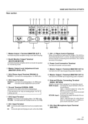
... effector of the external effector. Rear section NAME AND FUNCTION OF PARTS 1 23 4 5 6 7 9 8 9 MASTER BOOTH OUT 1 MONITOR L CH - 4 PHONO 3 CH - 3 PHONO 2 LINE L L CH - 2 PHONO 1 CD 2 / LINE CH - 1 LINE CD 1 L L R R R MASTER LEVEL ATT. SEND (Output) : Connects the input terminal of monaural input. Uses L channel input for adjusting sound. The sound that L and R are mixed will be sent to the analog player. (for a safety ground. 7 CH-2 Input Terminal PHONO 1 :Connects to the effector. CH-4 Sub Microphone Input Terminal (SUB MIC) 11 This terminal...
... effector of the external effector. Rear section NAME AND FUNCTION OF PARTS 1 23 4 5 6 7 9 8 9 MASTER BOOTH OUT 1 MONITOR L CH - 4 PHONO 3 CH - 3 PHONO 2 LINE L L CH - 2 PHONO 1 CD 2 / LINE CH - 1 LINE CD 1 L L R R R MASTER LEVEL ATT. SEND (Output) : Connects the input terminal of monaural input. Uses L channel input for adjusting sound. The sound that L and R are mixed will be sent to the analog player. (for a safety ground. 7 CH-2 Input Terminal PHONO 1 :Connects to the effector. CH-4 Sub Microphone Input Terminal (SUB MIC) 11 This terminal...
Owner's Manual
Page 12
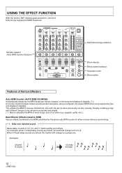
...ASSIGN B MASTER EFFECT 10 10 EFFECT SELECTOR 9 9 mSec 8 8 7 7 AUTO PAN FLANGER ECHO REVERB 6 6 DELAY PITCH % 5 5 SHIFTER 4 4 AUTO BPM SEND/ RETURN 3 3 2 2 CH.SELECTOR 1 1 34 0 0 2 MIC 1 MASTER MASTER BALANCE PARAMETER L R BOOTH MONITOR LEVEL MIN MAX EFFECT ON/OFF -∞ 0dB Real-time/average selection Effect selector Effect channel selector Parameter knob Effect switch Features of Various Effectors Auto BPM Counter (AUTO BPM COUNTER) Automatically measures the BPM (beats per minute (tempo)) of the song and displays it digitally. Delay...
...ASSIGN B MASTER EFFECT 10 10 EFFECT SELECTOR 9 9 mSec 8 8 7 7 AUTO PAN FLANGER ECHO REVERB 6 6 DELAY PITCH % 5 5 SHIFTER 4 4 AUTO BPM SEND/ RETURN 3 3 2 2 CH.SELECTOR 1 1 34 0 0 2 MIC 1 MASTER MASTER BALANCE PARAMETER L R BOOTH MONITOR LEVEL MIN MAX EFFECT ON/OFF -∞ 0dB Real-time/average selection Effect selector Effect channel selector Parameter knob Effect switch Features of Various Effectors Auto BPM Counter (AUTO BPM COUNTER) Automatically measures the BPM (beats per minute (tempo)) of the song and displays it digitally. Delay...
Owner's Manual
Page 13
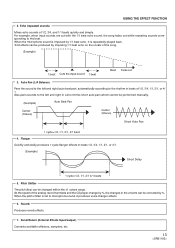
Pitch Shifter The pitch (key) can be performed manually. (Example) Auto Beat Pan Center (Stereo) Center (Stereo) Short Auto Pan 1 cycle=1/2, 1/1, 2/1, 4/1 beat 4. Send/Return (External Effects Input/output) Connects available effectors, samplers, etc. 13 Auto Pan (L-R Balance) Pans the sound to the rhythm in beats of the analog record turntable and the CD player change by %, the changes in the volume can be corrected by 1/1 beat echo, it produces voice changer effects. 6. Also pans...
Pitch Shifter The pitch (key) can be performed manually. (Example) Auto Beat Pan Center (Stereo) Center (Stereo) Short Auto Pan 1 cycle=1/2, 1/1, 2/1, 4/1 beat 4. Send/Return (External Effects Input/output) Connects available effectors, samplers, etc. 13 Auto Pan (L-R Balance) Pans the sound to the rhythm in beats of the analog record turntable and the CD player change by %, the changes in the volume can be corrected by 1/1 beat echo, it produces voice changer effects. 6. Also pans...
Owner's Manual
Page 14
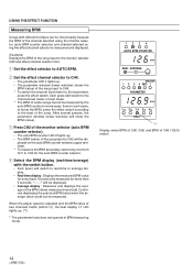
...-time display : Displays the measured BPM value for more than 5 seconds, "- - -" will be mixed easily because the BPM of the channel selected using the monitor selector (auto BPM counter selector) and channel selected using the effect channel selector is adjusted and the BPM value of two channels match (within ±1), the beat display 1/1 LED lights up. (*1) * The parameter knob does not operate in BPM measuring mode. 1234 AUTO BPM COUNTER BPM REAL AVERAGE MASTER 1 2 3 4 MIC PARAMETER BPM 1/2 3/4 1/1 2/1 4/1 BEAT *1 Display when BPM...
...-time display : Displays the measured BPM value for more than 5 seconds, "- - -" will be mixed easily because the BPM of the channel selected using the monitor selector (auto BPM counter selector) and channel selected using the effect channel selector is adjusted and the BPM value of two channels match (within ±1), the beat display 1/1 LED lights up. (*1) * The parameter knob does not operate in BPM measuring mode. 1234 AUTO BPM COUNTER BPM REAL AVERAGE MASTER 1 2 3 4 MIC PARAMETER BPM 1/2 3/4 1/1 2/1 4/1 BEAT *1 Display when BPM...
Owner's Manual
Page 15
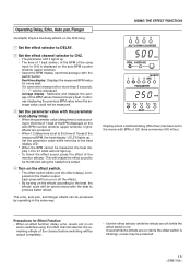
... effect function (delay, echo, reverb, etc.) is on and is switched using the headphone output. 4 Turn on the effect switch. • The effect switch blinks and the effect (delay) is imposed on the master output. Each press will turn on or off (while the effect switch is lit). Operating Delay, Echo, Auto pan, Flanger (Example) Impose the delay effects on the CH2 song. 1 Set the effect selector to DELAY. 2 Set the effect channel selector to CH2. • The parameter LED 2 lights up. • The time...
... effect function (delay, echo, reverb, etc.) is on and is switched using the headphone output. 4 Turn on the effect switch. • The effect switch blinks and the effect (delay) is imposed on the master output. Each press will turn on or off (while the effect switch is lit). Operating Delay, Echo, Auto pan, Flanger (Example) Impose the delay effects on the CH2 song. 1 Set the effect selector to DELAY. 2 Set the effect channel selector to CH2. • The parameter LED 2 lights up. • The time...
Owner's Manual
Page 16
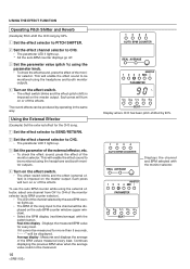
... effect (pitch shift) is imposed on the auto BPM counter window (upper window). • Select the BPM display (real-time/average) with the monitor selector. Average display : Measures and displays the average of the monitor selector. MASTER 1 2 3 4 MIC PARAMETER 1/2 3/4 1/1 2/1 4/1 BEAT This will enable the effect sound to be displayed on the master output. This will enable the effect sound to be displayed. Each press will be monitored using the headphone and booth monitor outputs. 4 Turn on the effect switch. • The effect switch...
... effect (pitch shift) is imposed on the auto BPM counter window (upper window). • Select the BPM display (real-time/average) with the monitor selector. Average display : Measures and displays the average of the monitor selector. MASTER 1 2 3 4 MIC PARAMETER 1/2 3/4 1/1 2/1 4/1 BEAT This will enable the effect sound to be displayed on the master output. This will enable the effect sound to be displayed. Each press will be monitored using the headphone and booth monitor outputs. 4 Turn on the effect switch. • The effect switch...

Owner's Manual
Page 17
... ECHO REVERB 6 6 DELAY PITCH % 5 5 SHIFTER 4 4 AUTO BPM SEND/ RETURN 3 3 2 2 CH.SELECTOR 1 1 34 0 0 2 MIC 1 MASTER MASTER BALANCE PARAMETER L R BOOTH MONITOR LEVEL MIN MAX EFFECT ON/OFF -∞ 0dB Cross fader switch Assign (B) switch Cross fader control Fader Start Play When the DJ mixer DJM-500 and the CD player CDJ-500G for the player to standby at this case, there is completely returned to the original position, the player will back cue (returns to the cue point). The cross fader can also be used...
... ECHO REVERB 6 6 DELAY PITCH % 5 5 SHIFTER 4 4 AUTO BPM SEND/ RETURN 3 3 2 2 CH.SELECTOR 1 1 34 0 0 2 MIC 1 MASTER MASTER BALANCE PARAMETER L R BOOTH MONITOR LEVEL MIN MAX EFFECT ON/OFF -∞ 0dB Cross fader switch Assign (B) switch Cross fader control Fader Start Play When the DJ mixer DJM-500 and the CD player CDJ-500G for the player to standby at this case, there is completely returned to the original position, the player will back cue (returns to the cue point). The cross fader can also be used...
Owner's Manual
Page 18
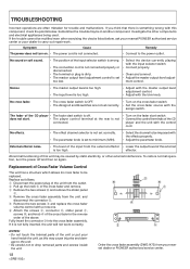
... PIONEER authorized service center or your nearest dealer or PIONEER authorized service center. Abnormal functioning of the CD player • The fader start . • The player control terminal at the rear is set too low. • Select the device currently playing with the input selector switch. • Connect properly. • Clean and connect. • Adjust the master output level adjust- TROUBLESHOOTING Incorrect operations are not set correctly. • Set the cross-fader source with the assign switch. Investigate the other external...
... PIONEER authorized service center or your nearest dealer or PIONEER authorized service center. Abnormal functioning of the CD player • The fader start . • The player control terminal at the rear is set too low. • Select the device currently playing with the input selector switch. • Connect properly. • Clean and connect. • Adjust the master output level adjust- TROUBLESHOOTING Incorrect operations are not set correctly. • Set the cross-fader source with the assign switch. Investigate the other external...

Owner's Manual
Page 19
SPECIFICATIONS Audio Section Input terminal (Input level/impedance) CD/LINE 14 dBV (200 mV) / 22 kΩ PHONO 54 dBV (2 mV) / 47 kΩ MAIN MIC 54 dBV (2 mV) / 3 kΩ SUB MIC 60 dBV (1 mV) / 3 kΩ RETURN 14 dBV (200 mV) / 22 kΩ Output terminal (Output level/impedance) MASTER OUT 1 (RCA 0 dBV (1 V) / 1 kΩ MASTER OUT 2 (XLR 4 dBm (1.23 V) / 600 Ω MASTER OUT 3 (1/4"PHONE 0 dBV (1 V) / 1 kΩ BOOTH MONITOR 0 dBV (1 V) / 1 kΩ SEND 0 dBV...
SPECIFICATIONS Audio Section Input terminal (Input level/impedance) CD/LINE 14 dBV (200 mV) / 22 kΩ PHONO 54 dBV (2 mV) / 47 kΩ MAIN MIC 54 dBV (2 mV) / 3 kΩ SUB MIC 60 dBV (1 mV) / 3 kΩ RETURN 14 dBV (200 mV) / 22 kΩ Output terminal (Output level/impedance) MASTER OUT 1 (RCA 0 dBV (1 V) / 1 kΩ MASTER OUT 2 (XLR 4 dBm (1.23 V) / 600 Ω MASTER OUT 3 (1/4"PHONE 0 dBV (1 V) / 1 kΩ BOOTH MONITOR 0 dBV (1 V) / 1 kΩ SEND 0 dBV...

Owner's Manual
Page 20
PIONEER ELECTRONICS OF CANADA, INC. 300 Allstate Parkway, Markham, Ontario L3R OP2, Canada Printed in Japan All rights reserved. PIONEER ELECTRONIC CORPORATION 4-1, Meguro 1-Chome, Meguro-ku, Tokyo 153, Japan PIONEER NEW MEDIA TECHNOLOGIES, INC. 2265 East 220th Street, Long Beach, California 90810, U.S.A. Published by Pioneer Electronic Corporation. Copyright © 1995 Pioneer Electronic Corporation.
PIONEER ELECTRONICS OF CANADA, INC. 300 Allstate Parkway, Markham, Ontario L3R OP2, Canada Printed in Japan All rights reserved. PIONEER ELECTRONIC CORPORATION 4-1, Meguro 1-Chome, Meguro-ku, Tokyo 153, Japan PIONEER NEW MEDIA TECHNOLOGIES, INC. 2265 East 220th Street, Long Beach, California 90810, U.S.A. Published by Pioneer Electronic Corporation. Copyright © 1995 Pioneer Electronic Corporation.


