Installation Manual
Page 4
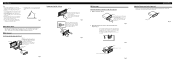
... out to remove the frame. (When reattaching the frame, point the side with a groove downwards and attach it.) Insert the supplied extraction keys into place. Fixing screw Fig. 10 For details, refer to ensure proper installation. The use the supplied fixing screws and fix the ... truss screws (5 × 8 mm) or flush surface screws (5 × 9 mm), depending on the shape of unit chassis). Fig. 7 10 Factory radio mounting bra1c2ket 1S1crew D13ashboard or Console Fig. 8 Fig. 9 About the fixing screws for instance, near a heater outlet. • If installation angle exceeds 60&#...
... out to remove the frame. (When reattaching the frame, point the side with a groove downwards and attach it.) Insert the supplied extraction keys into place. Fixing screw Fig. 10 For details, refer to ensure proper installation. The use the supplied fixing screws and fix the ... truss screws (5 × 8 mm) or flush surface screws (5 × 9 mm), depending on the shape of unit chassis). Fig. 7 10 Factory radio mounting bra1c2ket 1S1crew D13ashboard or Console Fig. 8 Fig. 9 About the fixing screws for instance, near a heater outlet. • If installation angle exceeds 60&#...
