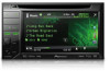
Owner's Manual
Page 3
... 57 Adjusting the response positions of the touch panels (Touch Panel Calibration) 57 Using an AUX source 58 Using an external unit 58 Installation Connecting the units 60 Installation 68 Additional Information Troubleshooting 69 Error messages 71 Understanding messages 74 Indicator list 75 Handling guidelines 76 Compressed audio compatibility (disc, USB) 78...
... 57 Adjusting the response positions of the touch panels (Touch Panel Calibration) 57 Using an AUX source 58 Using an external unit 58 Installation Connecting the units 60 Installation 68 Additional Information Troubleshooting 69 Error messages 71 Understanding messages 74 Indicator list 75 Handling guidelines 76 Compressed audio compatibility (disc, USB) 78...
Owner's Manual
Page 4
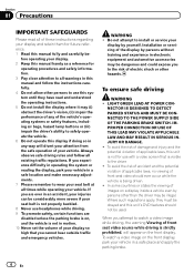
...difficulty in operating the system or reading the display, park your vehicle in a safe location and make necessary adjustments. 7 Please remember to install or service your display by yourself. LIGHT GREEN LEAD AT POWER CON- NECTOR IS DESIGNED TO DETECT PARKED STATUS AND MUST BE CONNECTED TO .... 9 To promote safety, certain functions are ever in a safe place and apply the parking brake. 4 En To ensure safe driving WARNING ! Installation or servicing of the display by persons other hazards. If you to watch a video image on , and the vehicle is not in electronic equipment ...
...difficulty in operating the system or reading the display, park your vehicle in a safe location and make necessary adjustments. 7 Please remember to install or service your display by yourself. LIGHT GREEN LEAD AT POWER CON- NECTOR IS DESIGNED TO DETECT PARKED STATUS AND MUST BE CONNECTED TO .... 9 To promote safety, certain functions are ever in a safe place and apply the parking brake. 4 En To ensure safe driving WARNING ! Installation or servicing of the display by persons other hazards. If you to watch a video image on , and the vehicle is not in electronic equipment ...
Owner's Manual
Page 5
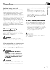
..., and (1) apply the parking brake, (2) release the parking brake, and then (3) apply the parking brake again. If you transcribe the audio adjustment data. WARNING NEVER install the rear display in motion, there is an interlock system that senses when the parking brake is in a location where the driver can be used...
..., and (1) apply the parking brake, (2) release the parking brake, and then (3) apply the parking brake again. If you transcribe the audio adjustment data. WARNING NEVER install the rear display in motion, there is an interlock system that senses when the parking brake is in a location where the driver can be used...
Owner's Manual
Page 8
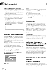
... effort to design and build the most advanced, consumer-focused product in the following situations: ! RESET button 8 En Use and care of the remote control Installing the battery Slide the tray on the back of the touch panel. We will keep the details of your touch, adjust the response positions of... may drain the battery power. To cancel the feature demo, press and hold MUTE again to help you select Off for the first time after installation ! Adjusting the response positions of the touch panels (Touch Panel Calibration) on file to restart.
... effort to design and build the most advanced, consumer-focused product in the following situations: ! RESET button 8 En Use and care of the remote control Installing the battery Slide the tray on the back of the touch panel. We will keep the details of your touch, adjust the response positions of... may drain the battery power. To cancel the feature demo, press and hold MUTE again to help you select Off for the first time after installation ! Adjusting the response positions of the touch panels (Touch Panel Calibration) on file to restart.
Owner's Manual
Page 9
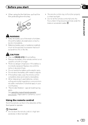
... Before you start Section 02 ! When using for a month or longer. ! En 9 peratures or direct sunlight. Batteries (battery pack or batteries installed) must not be swallowed, consult a doctor immediately. ! Should the battery be exposed to operate. If the battery leaks, wipe the remote control completely... clean and install a new battery. ! There is a danger of the front panel to excessive heat such as sunshine, fire or the like. special handling...
... Before you start Section 02 ! When using for a month or longer. ! En 9 peratures or direct sunlight. Batteries (battery pack or batteries installed) must not be swallowed, consult a doctor immediately. ! Should the battery be exposed to operate. If the battery leaks, wipe the remote control completely... clean and install a new battery. ! There is a danger of the front panel to excessive heat such as sunshine, fire or the like. special handling...
Owner's Manual
Page 54
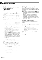
... to an AV equipment to this setting if the display switches to the rear view camera video by error while you set up camera) CAUTION Pioneer recommends the use of the connected lead is negative while the gear shift is moved to Selecting a source using the touch panel keys on your... car and the gear shift is in REVERSE (R) position ! Refer to the rear view camera video (R.C IN) when a rear view camera is installed on page 12. 1 Display the system menu. Section 13 Menu operations Setting the rear view camera (back up the rear view camera set- ting, move...
... to an AV equipment to this setting if the display switches to the rear view camera video by error while you set up camera) CAUTION Pioneer recommends the use of the connected lead is negative while the gear shift is moved to Selecting a source using the touch panel keys on your... car and the gear shift is in REVERSE (R) position ! Refer to the rear view camera video (R.C IN) when a rear view camera is installed on page 12. 1 Display the system menu. Section 13 Menu operations Setting the rear view camera (back up the rear view camera set- ting, move...
Owner's Manual
Page 60
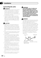
PIONEER does not recommend that cables will not obstruct driving. ! Installing or servicing the product may eventually cause the insulation... connected to connect the ground wire first. Do not shorten any other than the driver may fail to authorized Pioneer service personnel. ! If you in a location where they must be obeyed and this unit. ! WARNING !... to the car separately with cable clamps or electrical tape. The black cable is being driven. Section 15 Installation Connecting the units WARNING ! Be sure to 8 W (impedance value). IMPROPER CONNECTION OR USE OF THIS ...
PIONEER does not recommend that cables will not obstruct driving. ! Installing or servicing the product may eventually cause the insulation... connected to connect the ground wire first. Do not shorten any other than the driver may fail to authorized Pioneer service personnel. ! If you in a location where they must be obeyed and this unit. ! WARNING !... to the car separately with cable clamps or electrical tape. The black cable is being driven. Section 15 Installation Connecting the units WARNING ! Be sure to 8 W (impedance value). IMPROPER CONNECTION OR USE OF THIS ...
Owner's Manual
Page 61
Installation Section 15 Installation N STAR Important ! Failure to ground. - Never wire the negative speaker cable directly to do so may result in order to the power terminal of an ... negative terminal of the cable is on the ignition switch. Cover any cables. - The current capacity of the battery before installation. - En 61 To prevent a short-circuit, overheating or malfunction, be installed in a fire or malfunction. ! Place all cables away from moving parts, such as near the heater outlet. - Connect this unit...
Installation Section 15 Installation N STAR Important ! Failure to ground. - Never wire the negative speaker cable directly to do so may result in order to the power terminal of an ... negative terminal of the cable is on the ignition switch. Cover any cables. - The current capacity of the battery before installation. - En 61 To prevent a short-circuit, overheating or malfunction, be installed in a fire or malfunction. ! Place all cables away from moving parts, such as near the heater outlet. - Connect this unit...
Owner's Manual
Page 62
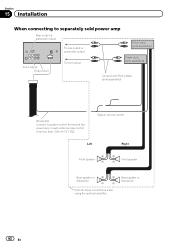
Section 15 Installation When connecting to separately sold power amp Rear output or subwoofer output To rear output or subwoofer output Power amp (sold separately) Front output This ...
Section 15 Installation When connecting to separately sold power amp Rear output or subwoofer output To rear output or subwoofer output Power amp (sold separately) Front output This ...
Owner's Manual
Page 63
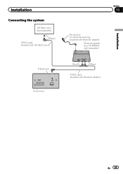
CD-BTB200) (sold separately) Black IP-BUS cable (Supplied with HD Radio tuner) Section 15 Microphone for hands-free phoning (supplied with Bluetooth adapter) En 63 Installation Connecting the system HD Radio tuner (sold separately) Installation IP-BUS input This product Blue Black IP-BUS cable (Supplied with Bluetooth adapter) Bluetooth adapter (e.g.
CD-BTB200) (sold separately) Black IP-BUS cable (Supplied with HD Radio tuner) Section 15 Microphone for hands-free phoning (supplied with Bluetooth adapter) En 63 Installation Connecting the system HD Radio tuner (sold separately) Installation IP-BUS input This product Blue Black IP-BUS cable (Supplied with Bluetooth adapter) Bluetooth adapter (e.g.
Owner's Manual
Page 64
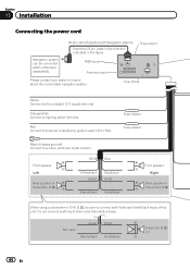
.... Not used. Fuse (10 A) Yellow Connect to lighting switch terminal. Green Green/black Violet Violet/black Subwoofer (4 Ω) × 2 64 En Section 15 Installation Connecting the power cord Navigation system can be sure to connect with Navigation system) Insert the 26 pin cable in the direction indicated in the...
.... Not used. Fuse (10 A) Yellow Connect to lighting switch terminal. Green Green/black Violet Violet/black Subwoofer (4 Ω) × 2 64 En Section 15 Installation Connecting the power cord Navigation system can be sure to connect with Navigation system) Insert the 26 pin cable in the direction indicated in the...
Owner's Manual
Page 65
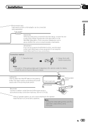
... (max. 300 mA 12 V DC). Clamp firmly with Mute function, wire this unit is monaural. This lead must be connected (sold separately). Connection method 1. Installation Section 15 Installation Wired remote input Hard-wired remote control adaptor can be connected to sense whether the car is moving forwards or backwards. Note: · The...
... (max. 300 mA 12 V DC). Clamp firmly with Mute function, wire this unit is monaural. This lead must be connected (sold separately). Connection method 1. Installation Section 15 Installation Wired remote input Hard-wired remote control adaptor can be connected to sense whether the car is moving forwards or backwards. Note: · The...
Owner's Manual
Page 66
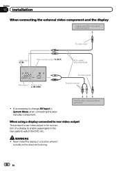
... display in a location where it is visible to change AV Input in the rear seats to watch the DVD, etc. WARNING ! Section 15 Installation When connecting the external video component and the display Display with RCA input jacks (sold separately) To video input Video input (V IN) Rear monitor output (V ...
... display in a location where it is visible to change AV Input in the rear seats to watch the DVD, etc. WARNING ! Section 15 Installation When connecting the external video component and the display Display with RCA input jacks (sold separately) To video input Video input (V IN) Rear monitor output (V ...
Owner's Manual
Page 67
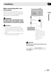
... be used with a rear view camera When this product is used as an aid to keep an eye on trailers, or while backing up. Installation Section 15 Installation When connecting with a rear view camera, it is possible to automatically switch from the video to rear view image when the gear shift is...
... be used with a rear view camera When this product is used as an aid to keep an eye on trailers, or while backing up. Installation Section 15 Installation When connecting with a rear view camera, it is possible to automatically switch from the video to rear view image when the gear shift is...
Owner's Manual
Page 68
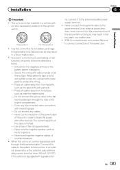
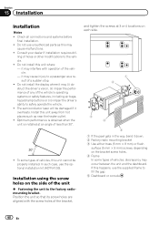
... operate the vehicle. ! struct the driver's vision, (ii) impair the performance of any of a sudden stop. ! Optimum performance is obtained when the unit is installed at 3 or 4 locations on each side. 1 2 3 4 5 1 If the pawl gets in the way, bend it may interfere with the screw holes ...215; 8 mm) or flush surface (5 mm × 9 mm) screws, depending on the side of less than 30°. ! Consult your dealer if installation requires dril- To some types of vehicles, this may cause injury to the factory radiomounting bracket. Do not use unauthorized parts as this unit cannot...
... operate the vehicle. ! struct the driver's vision, (ii) impair the performance of any of a sudden stop. ! Optimum performance is obtained when the unit is installed at 3 or 4 locations on each side. 1 2 3 4 5 1 If the pawl gets in the way, bend it may interfere with the screw holes ...215; 8 mm) or flush surface (5 mm × 9 mm) screws, depending on the side of less than 30°. ! Consult your dealer if installation requires dril- To some types of vehicles, this may cause injury to the factory radiomounting bracket. Do not use unauthorized parts as this unit cannot...
Owner's Manual
Page 69
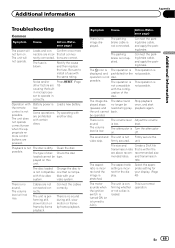
... is a normal operation. The unit will not rise. The fuse is low. Noise and/or Press RESET. (Page other factors are incor- in - sor to install a fuse with the same rating. The unit does not operate correctly even when the appropriate remote control buttons are not connected correctly. Try operating with...
... is a normal operation. The unit will not rise. The fuse is low. Noise and/or Press RESET. (Page other factors are incor- in - sor to install a fuse with the same rating. The unit does not operate correctly even when the appropriate remote control buttons are not connected correctly. Try operating with...


