Installation Manual
Page 2
... tested and found to comply with the instructions, may invalidate the user's right to correct the interference by turning the equipment off plug must be perfomed only by qualified service personnel. These limits are used in a residential installation. D8-10-2_En CAUTION: This product satisfies FCC regulations when shielded cables and connectors are designed to other equipment...
... tested and found to comply with the instructions, may invalidate the user's right to correct the interference by turning the equipment off plug must be perfomed only by qualified service personnel. These limits are used in a residential installation. D8-10-2_En CAUTION: This product satisfies FCC regulations when shielded cables and connectors are designed to other equipment...
Installation Manual
Page 3
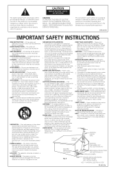
...; When the product exhibits a distinct change in installation such as this product from the wall outlet and disconnect the antenna or cable system. SAFETY CHECK - NO USER-SERVICEABLE PARTS INSIDE. All operating and use attachments not recommended by the product manufacturer as the original part. The product should still fail to fit, contact your obsolete outlet. for service. If you are covered by following...
...; When the product exhibits a distinct change in installation such as this product from the wall outlet and disconnect the antenna or cable system. SAFETY CHECK - NO USER-SERVICEABLE PARTS INSIDE. All operating and use attachments not recommended by the product manufacturer as the original part. The product should still fail to fit, contact your obsolete outlet. for service. If you are covered by following...

Installation Manual
Page 4
... 6 Installing the receiver 6 Making cable connections 6 Loading the batteries 6 Operating range of remote control unit. . . . 7 02 5 minute guide Introduction to home theater 8 Listening to Surround Sound 9 Using the Quick Setup 12 03 Quick surround sound setup Automatically calibrating your listening area (MCACC 14 04 Connecting up Audio/Video cords 16 S-video cables 16 Component video cords 16 Digital audio coaxial cords/ Optical cables 16 Connecting digital...
... 6 Installing the receiver 6 Making cable connections 6 Loading the batteries 6 Operating range of remote control unit. . . . 7 02 5 minute guide Introduction to home theater 8 Listening to Surround Sound 9 Using the Quick Setup 12 03 Quick surround sound setup Automatically calibrating your listening area (MCACC 14 04 Connecting up Audio/Video cords 16 S-video cables 16 Component video cords 16 Digital audio coaxial cords/ Optical cables 16 Connecting digital...
Installation Manual
Page 6
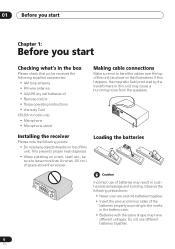
...not use new and old batteries together. • Insert the plus and minus sides of the batteries properly according to the marks in the illustration). Loading the batteries Incorrect use of batteries may result in this unit may have different ...batteries x2 • Remote control • These operating instructions • Warranty Card VSX-D914 model only: • Microphone • Microphone stand Making cable connections Make sure not to bend the cables over the top of this unit (as leakage and bursting. Observe the following precautions: • Never use different batteries...
...not use new and old batteries together. • Insert the plus and minus sides of the batteries properly according to the marks in the illustration). Loading the batteries Incorrect use of batteries may result in this unit may have different ...batteries x2 • Remote control • These operating instructions • Warranty Card VSX-D914 model only: • Microphone • Microphone stand Making cable connections Make sure not to bend the cables over the top of this unit (as leakage and bursting. Observe the following precautions: • Never use different batteries...
Installation Manual
Page 9
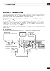
... SINGLE SEE INSTRUCTION MANUAL MONITOR A B IN PLAY S OUT R AUDIO L DVD IN / LD FRONT D V D 5.1CH REC INPUT CD-R IN /TAPE / MD SUB WOOFER PREOUT Video cord 9 En For surround sound, you can do this with the following quick setup guide, you should refer to Digital input settings on your DVD player to the receiver using an optical cable, you should...
... SINGLE SEE INSTRUCTION MANUAL MONITOR A B IN PLAY S OUT R AUDIO L DVD IN / LD FRONT D V D 5.1CH REC INPUT CD-R IN /TAPE / MD SUB WOOFER PREOUT Video cord 9 En For surround sound, you can do this with the following quick setup guide, you should refer to Digital input settings on your DVD player to the receiver using an optical cable, you should...
Installation Manual
Page 10
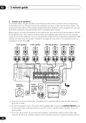
... see Speaker setting on page 43) to the audio input jack on the speakers. In this unit to large. • To use speakers with just two stereo speakers (the front speakers in the manner shown below ). 10 En The receiver will vary. 02 5 minute guide 3 Connect ... an impedance of eight speakers (including the subwoofer) is best. A complete setup of less than 8Ω). Front speakers L R Center speaker C Surround speakers Surround back speakers LS RS SBL SBR CENTER IN DIGITAL OUT OPT IN AUX COMPONENT VIDEO ASSIGNABLE FM UNBAL AM CD 75 Ω LOOP ANTENNA ...
... see Speaker setting on page 43) to the audio input jack on the speakers. In this unit to large. • To use speakers with just two stereo speakers (the front speakers in the manner shown below ). 10 En The receiver will vary. 02 5 minute guide 3 Connect ... an impedance of eight speakers (including the subwoofer) is best. A complete setup of less than 8Ω). Front speakers L R Center speaker C Surround speakers Surround back speakers LS RS SBL SBR CENTER IN DIGITAL OUT OPT IN AUX COMPONENT VIDEO ASSIGNABLE FM UNBAL AM CD 75 Ω LOOP ANTENNA ...

Installation Manual
Page 11
.... Check the manual that came with the TV if you can select. See also Choosing your receiver setup on page 42 for more setup options. • Depending on your system on page 35 for more complete surround sound setup, we recommend using the automatic MCACC setup in the receiver and switch it should already be set to STANDARD...
.... Check the manual that came with the TV if you can select. See also Choosing your receiver setup on page 42 for more setup options. • Depending on your system on page 35 for more complete surround sound setup, we recommend using the automatic MCACC setup in the receiver and switch it should already be set to STANDARD...
Installation Manual
Page 12
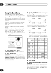
... QUICK SETUP VIDEO INPUT S-VIDEO VIDEO L AUDIO R ENTER MULTI JOG MASTER VOLUME DOWN UP 3 Use the MULTI JOG dial to choose your setup for the steps below to find the speaker setup that you don't have selected your speaker setup, room size and listening position. Use the ...room. 12 En 02 5 minute guide Using the Quick Setup You can use the automatic MCACC setup instead (in this case, go straight to the Quick surround sound setup on page 14). The receiver automatically makes the necessary settings after you have to make more specific settings, refer to Choosing your room size....
... QUICK SETUP VIDEO INPUT S-VIDEO VIDEO L AUDIO R ENTER MULTI JOG MASTER VOLUME DOWN UP 3 Use the MULTI JOG dial to choose your setup for the steps below to find the speaker setup that you don't have selected your speaker setup, room size and listening position. Use the ...room. 12 En 02 5 minute guide Using the Quick Setup You can use the automatic MCACC setup instead (in this case, go straight to the Quick surround sound setup on page 14). The receiver automatically makes the necessary settings after you have to make more specific settings, refer to Choosing your room size....
Installation Manual
Page 14
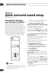
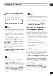
... MCACC SETUP MIC DIGITAL IN VIDEO INPUT S-VIDEO VIDEO L AUDIO R MULTI JOG 2 Place the microphone at your particular room. INPUT ATT FL DIMMER +10 D.ACCESS TOP MENU SETUP TUNE SR DISC ENTER CLASS MENU DTVMENU ST T.EDIT ENTER ST MCACC SETUP BAND GUIDE TUNE...setup Chapter 3: Quick surround sound setup VSX-D914 model only Automatically calibrating your listening area (MCACC) The Multi-Channel Acoustic Calibration (MCACC) system measures the acoustic characteristics of test tones to turn the power on. 4 If you have set up the microphone provided with your system, the receiver uses...
... MCACC SETUP MIC DIGITAL IN VIDEO INPUT S-VIDEO VIDEO L AUDIO R MULTI JOG 2 Place the microphone at your particular room. INPUT ATT FL DIMMER +10 D.ACCESS TOP MENU SETUP TUNE SR DISC ENTER CLASS MENU DTVMENU ST T.EDIT ENTER ST MCACC SETUP BAND GUIDE TUNE...setup Chapter 3: Quick surround sound setup VSX-D914 model only Automatically calibrating your listening area (MCACC) The Multi-Channel Acoustic Calibration (MCACC) system measures the acoustic characteristics of test tones to turn the power on. 4 If you have set up the microphone provided with your system, the receiver uses...

Installation Manual
Page 15
... a subwoofer is selected, you have connected a subwoofer, it will end up with the operation of around 5 inches (12cm) will check for five seconds. If you can correct the setting manually using CH SELECT (to check channel levels) or by the ERR message (see the notes regarding...different size settings. The MCACC indicator then lights to finish the auto surround setup. If this seems to be affecting the environment and switch them off the walls, obstacles blocking the speakers from the microphone) the final settings may be happening, switch off the power, and check the problem...
... a subwoofer is selected, you have connected a subwoofer, it will end up with the operation of around 5 inches (12cm) will check for five seconds. If you can correct the setting manually using CH SELECT (to check channel levels) or by the ERR message (see the notes regarding...different size settings. The MCACC indicator then lights to finish the auto surround setup. If this seems to be affecting the environment and switch them off the walls, obstacles blocking the speakers from the microphone) the final settings may be happening, switch off the power, and check the problem...
Installation Manual
Page 16
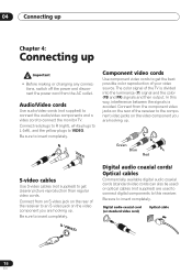
...S-video cables Use S-video cables (not supplied) to get the best possible color reproduction of the receiver to the component video jacks on the rear of your video source. Be sure to insert completely. R L VIDEO Component video cords Use component video cords...Digital audio coaxial cord (or standard video cord) Optical cable 16 En S VIDEO Digital audio coaxial cords/ Optical cables Commercially available digital audio coaxial cords (standard video cords can also be used to connect digital components to get clearer picture reproduction than regular video cords. Be sure to VIDEO...
...S-video cables Use S-video cables (not supplied) to get the best possible color reproduction of the receiver to the component video jacks on the rear of your video source. Be sure to insert completely. R L VIDEO Component video cords Use component video cords...Digital audio coaxial cord (or standard video cord) Optical cable 16 En S VIDEO Digital audio coaxial cords/ Optical cables Commercially available digital audio coaxial cords (standard video cords can also be used to connect digital components to get clearer picture reproduction than regular video cords. Be sure to VIDEO...
Installation Manual
Page 21
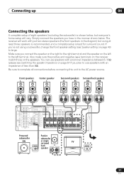
...'s home setup will work with just two stereo speakers (the front speakers in the diagram) but using a subwoofer, change the front speaker setting (see...using at least three speakers is recommended, and a complete setup is shown below . The receiver will vary. Make sure you plan to use speakers with an impedance of eight speakers (including the subwoofer) is best... PREOUT /LD IN S-VIDEO Y PB PR Y PB PR R R CENTER (T V / SAT)IN ø FRONT SURROUND PREOUT S R FRONT L P E A K A E R CENTER R SURROUND BACK L R SURROUND L SINGLE SEE INSTRUCTION MANUAL R FRONT L B...
...'s home setup will work with just two stereo speakers (the front speakers in the diagram) but using a subwoofer, change the front speaker setting (see...using at least three speakers is recommended, and a complete setup is shown below . The receiver will vary. Make sure you plan to use speakers with an impedance of eight speakers (including the subwoofer) is best... PREOUT /LD IN S-VIDEO Y PB PR Y PB PR R R CENTER (T V / SAT)IN ø FRONT SURROUND PREOUT S R FRONT L P E A K A E R CENTER R SURROUND BACK L R SURROUND L SINGLE SEE INSTRUCTION MANUAL R FRONT L B...
Installation Manual
Page 22
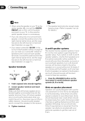
... supporting the full speaker setup. others should also follow the guidelines on placement that all the bare speaker wire is twisted together and inserted fully into the speaker terminal. Use good...see illustration on page 10). • If you select subwoofer (SB SW) in the Surround back speaker setting on page 44 you can hook up a subwoofer instead of them. 22 En Speaker terminals 1 2 3 ...or both). In this unit to speaker manual for details.) A and B speaker systems The receiver has two speaker systems: A and B. 04 Connecting up • When using the speaker on your TV as a ...
... supporting the full speaker setup. others should also follow the guidelines on placement that all the bare speaker wire is twisted together and inserted fully into the speaker terminal. Use good...see illustration on page 10). • If you select subwoofer (SB SW) in the Surround back speaker setting on page 44 you can hook up a subwoofer instead of them. 22 En Speaker terminals 1 2 3 ...or both). In this unit to speaker manual for details.) A and B speaker systems The receiver has two speaker systems: A and B. 04 Connecting up • When using the speaker on your TV as a ...
Installation Manual
Page 26
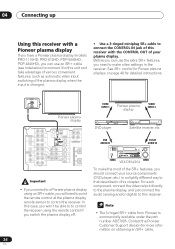
... (models PRO-1110HD, PRO-910HD, PDP-5040HD, PDP-4340HD), you can use an SR+ cable (see note below) to connect it to this unit and take advantage of various convenient features, such as automatic video input switching of the plasma display when the input is commercially available under the part number ADE7095. Contact the Pioneer Customer Support division for detailed instructions. See...
... (models PRO-1110HD, PRO-910HD, PDP-5040HD, PDP-4340HD), you can use an SR+ cable (see note below) to connect it to this unit and take advantage of various convenient features, such as automatic video input switching of the plasma display when the input is commercially available under the part number ADE7095. Contact the Pioneer Customer Support division for detailed instructions. See...
Installation Manual
Page 49
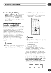
...in turns, so you to set the speaker levels and channel delay to your left front speaker as a reference point to adjust each channel level in the following order (depending on the plasma display. • VSX-D914 model only - For example, VIDEO:4 matches the VIDEO input with your speaker levels...MENU DTVMENU ST T.EDIT ENTER ST MCACC SETUP BAND GUIDE TUNE TV CONTROL RETURN TV VOL INPUT SELECT TV CH VOL • These test tones can judge which needs to use the MCACC manual setup. VIDEO:5 or TV - These are calibrated according to the distance from the front panel to to be...
...in turns, so you to set the speaker levels and channel delay to your left front speaker as a reference point to adjust each channel level in the following order (depending on the plasma display. • VSX-D914 model only - For example, VIDEO:4 matches the VIDEO input with your speaker levels...MENU DTVMENU ST T.EDIT ENTER ST MCACC SETUP BAND GUIDE TUNE TV CONTROL RETURN TV VOL INPUT SELECT TV CH VOL • These test tones can judge which needs to use the MCACC manual setup. VIDEO:5 or TV - These are calibrated according to the distance from the front panel to to be...
Installation Manual
Page 51
...the test tone. The front panel display shows SR+ CHECK, then the new setting is ± 10 dB. 6 When you 're listening to make using LEVEL +/-. The test tone is . • Using test tones to make sure you don't hear a test tone from each...Automatic video input switching on the plasma display. • Automatic volume muting on page 48 for the STANDARD or ADVANCED SURROUND modes. • If you have correctly specified your Pioneer plasma display even easier. Setting up the receiver 07 3 Press TEST TONE to the Standard mode. Using the SR+ mode with your speaker setup...
...the test tone. The front panel display shows SR+ CHECK, then the new setting is ± 10 dB. 6 When you 're listening to make using LEVEL +/-. The test tone is . • Using test tones to make sure you don't hear a test tone from each...Automatic video input switching on the plasma display. • Automatic volume muting on page 48 for the STANDARD or ADVANCED SURROUND modes. • If you have correctly specified your Pioneer plasma display even easier. Setting up the receiver 07 3 Press TEST TONE to the Standard mode. Using the SR+ mode with your speaker setup...
Installation Manual
Page 59
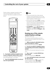
... and 5. The remote LCD display shows SETUP. 2 Press the the MULTI CONTROL button corresponding to the button setting to be learned from other remote controls. NO CODE is displayed if there is full. The LCD on the remote displays the component. 3 Use and to confirm the button has been ...represent operations that cannot be erased. The buttons available are shown below to erase a programmed button you have programmed and restores the button to free up more memory. • TV CONTROL buttons (TV ,TV VOL +/-, TV CH +/- Erasing one of the remote control button settings VSX-D914 model ...
... and 5. The remote LCD display shows SETUP. 2 Press the the MULTI CONTROL button corresponding to the button setting to be learned from other remote controls. NO CODE is displayed if there is full. The LCD on the remote displays the component. 3 Use and to confirm the button has been ...represent operations that cannot be erased. The buttons available are shown below to erase a programmed button you have programmed and restores the button to free up more memory. • TV CONTROL buttons (TV ,TV VOL +/-, TV CH +/- Erasing one of the remote control button settings VSX-D914 model ...

Installation Manual
Page 65
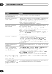
...sure there are often mistaken for servicing. If the trouble cannot be rectified even after exercising the checks listed below . Problem Remedy The power does not turn muting off. Additional information 11 Chapter 11: Additional information Troubleshooting Incorrect operations are no loose strands of speaker ... to page 20). • Adjust the direction and position for best reception. • Connect an additional internal or external AM antenna (refer to page 20). • Turn off automatically, take the unit to your nearest Pioneer authorized service center or your dealer to turn...
...sure there are often mistaken for servicing. If the trouble cannot be rectified even after exercising the checks listed below . Problem Remedy The power does not turn muting off. Additional information 11 Chapter 11: Additional information Troubleshooting Incorrect operations are no loose strands of speaker ... to page 20). • Adjust the direction and position for best reception. • Connect an additional internal or external AM antenna (refer to page 20). • Turn off automatically, take the unit to your nearest Pioneer authorized service center or your dealer to turn...
Installation Manual
Page 66
... the speaker settings. • Refer to Manually calibrating your listening area (MCACC) on page 49 or the (VSX-D914 model only) Quick surround sound setup on page 14 to check the speaker levels. • Refer to Using the Surround Back Channel (SB CH) on page 45 to 0 dB or 10 dB. • The Dolby Digital or...
... the speaker settings. • Refer to Manually calibrating your listening area (MCACC) on page 49 or the (VSX-D914 model only) Quick surround sound setup on page 14 to check the speaker levels. • Refer to Using the Surround Back Channel (SB CH) on page 45 to 0 dB or 10 dB. • The Dolby Digital or...
Installation Manual
Page 69
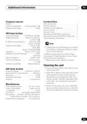
Cleaning the unit • Use a polishing cloth or dry cloth to the Federal Trade Commission's Trade Regulation rule on or near this unit, since these will corrode ...MAX. (SWITCHED) Dimensions . . . 420 (W) x 158 (H) x 401 (D) mm (16-9/16 (W) x 6-1/4 (H) x 15-13/16 (D) in.) Weight (without package). . . . . 10.6 kg (23.4 lb) Furnished Parts AM loop antenna 1 FM wire antenna 1 AA/LR6 dry cell batteries 2 Remote control 1 Warranty Card 1 Microphone (VSX-D914 model only 1 Microphone stand (VSX-D914 model only) . 1 These operating instructions 1 • Specifications and the design ...
Cleaning the unit • Use a polishing cloth or dry cloth to the Federal Trade Commission's Trade Regulation rule on or near this unit, since these will corrode ...MAX. (SWITCHED) Dimensions . . . 420 (W) x 158 (H) x 401 (D) mm (16-9/16 (W) x 6-1/4 (H) x 15-13/16 (D) in.) Weight (without package). . . . . 10.6 kg (23.4 lb) Furnished Parts AM loop antenna 1 FM wire antenna 1 AA/LR6 dry cell batteries 2 Remote control 1 Warranty Card 1 Microphone (VSX-D914 model only 1 Microphone stand (VSX-D914 model only) . 1 These operating instructions 1 • Specifications and the design ...

