Owner's Manual
Page 3
... that set the KURO apart. TABLE OF CONTENTS Congratulations on the Remote Control ...12 2 Install Your Flat Panel TV ...14 2.1 Choose a Location and the Mounting Method...14 2.1.1 Check the Location for Suitability ...15 2.1.2 Lift and/or Move Your Panel (the How To's)......Speaker Cables ...22 2.3 Wall/Ceiling Mounting...23 2.4 Mount the Flat Panel TV ...24 2.5 Attach the Color Sensor ...26 2.6 Connect to Broadcast TV & Other Devices (DVR, Receiver, BDR, etc 29 2.6.1 Add Analog (conventional) and Digital TV Channels 29 2.6.2 Connect Your Other Pioneer Equipment...29 2.6.3 Connect the Power ...
... that set the KURO apart. TABLE OF CONTENTS Congratulations on the Remote Control ...12 2 Install Your Flat Panel TV ...14 2.1 Choose a Location and the Mounting Method...14 2.1.1 Check the Location for Suitability ...15 2.1.2 Lift and/or Move Your Panel (the How To's)......Speaker Cables ...22 2.3 Wall/Ceiling Mounting...23 2.4 Mount the Flat Panel TV ...24 2.5 Attach the Color Sensor ...26 2.6 Connect to Broadcast TV & Other Devices (DVR, Receiver, BDR, etc 29 2.6.1 Add Analog (conventional) and Digital TV Channels 29 2.6.2 Connect Your Other Pioneer Equipment...29 2.6.3 Connect the Power ...
Owner's Manual
Page 6
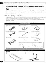
... with your installer to the ELITE Series Flat Panel TVs The Pioneer ELITE Series Flat Panel TV models include the 60-inch PRO-151FD and the 50-inch PRO-111FD (screen sizes measured diagonally). You will need a Philips screwdriver when mounting the speaker and attaching the stand. The PRO-151FD and PRO-111FD shipments have slightly different pieces. 01 Introduction to...
... with your installer to the ELITE Series Flat Panel TVs The Pioneer ELITE Series Flat Panel TV models include the 60-inch PRO-151FD and the 50-inch PRO-111FD (screen sizes measured diagonally). You will need a Philips screwdriver when mounting the speaker and attaching the stand. The PRO-151FD and PRO-111FD shipments have slightly different pieces. 01 Introduction to...
Owner's Manual
Page 7
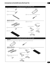
... Series Flat Panel TVs 01 Also shipped with the PRO-151FD (60" panel) Silver Screws (4) (4×10 mm) Falling Prevention Metal Fittings (2) Black Screws (4) (M6×20 mm) Light-Blocking Shield Screws to Metal Fittings (4) (M4×35 mm) Speaker accessories Speaker Cables (2) Speaker Mounting Screws (16) ...(M5×10 mm) Speaker Speaker Brackets for TOP-Right for BOTTOM-Right for TOP-Left for BOTTOM-Left Also shipped with the PRO-111FD (50" panel) Stand kit Falling Prevention Metal Fittings ...
... Series Flat Panel TVs 01 Also shipped with the PRO-151FD (60" panel) Silver Screws (4) (4×10 mm) Falling Prevention Metal Fittings (2) Black Screws (4) (M6×20 mm) Light-Blocking Shield Screws to Metal Fittings (4) (M4×35 mm) Speaker accessories Speaker Cables (2) Speaker Mounting Screws (16) ...(M5×10 mm) Speaker Speaker Brackets for TOP-Right for BOTTOM-Right for TOP-Left for BOTTOM-Left Also shipped with the PRO-111FD (50" panel) Stand kit Falling Prevention Metal Fittings ...
Owner's Manual
Page 14
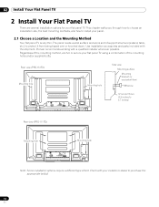
...down. Use installation accessories and parts included with your flat panel TV using a combination of bolt. Check with the shipment. Rear view (PRO-151FD) Mounting hole Mounting hole Side view Mounting surface Mounting bracket (or equivalent item) M8 screw 12 mm to 18 mm...14 En Regardless of the mounting method, anchor or secure your installer or dealer to 0.7 inches) Rear view (PRO-111FD) W Mounting hole W T W W Mounting hole W T W Note: Some installation options require a different type of the mounting holes and/or supplied bolts. Pioneer recommends working with a ...
...down. Use installation accessories and parts included with your flat panel TV using a combination of bolt. Check with the shipment. Rear view (PRO-151FD) Mounting hole Mounting hole Side view Mounting surface Mounting bracket (or equivalent item) M8 screw 12 mm to 18 mm...14 En Regardless of the mounting method, anchor or secure your installer or dealer to 0.7 inches) Rear view (PRO-111FD) W Mounting hole W T W W Mounting hole W T W Note: Some installation options require a different type of the mounting holes and/or supplied bolts. Pioneer recommends working with a ...
Owner's Manual
Page 15
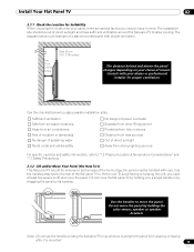
... for your dealer or professional installer for endurance but because of a stand-mounted panel with proper ventilation. Do not move the panel. Note: Do not use the handles to hang the flat panel TV or as anchors to prevent the panel from strong lighting sources For specific ... to "7.2 Physical Location & Temperature Considerations" and "7.7 Safety Precautions." 2.1.2 Lift and/or Move Your Panel (the How To's) This flat panel TV is mounted. 15 En Consult with care. To avoid flexing or twisting the unit, you need at least two people to allow cooling. Use the checklist below...
... for your dealer or professional installer for endurance but because of a stand-mounted panel with proper ventilation. Do not move the panel. Note: Do not use the handles to hang the flat panel TV or as anchors to prevent the panel from strong lighting sources For specific ... to "7.2 Physical Location & Temperature Considerations" and "7.7 Safety Precautions." 2.1.2 Lift and/or Move Your Panel (the How To's) This flat panel TV is mounted. 15 En Consult with care. To avoid flexing or twisting the unit, you need at least two people to allow cooling. Use the checklist below...
Owner's Manual
Page 16
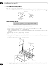
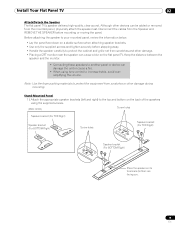
... panel TV on a soft cloth to avoid scratching. Screws (4 x 10 mm: silver) Screws (4 x 10 mm: silver) Rear Front Completed stand Sheet Base cover Note: Assemble the stand with the Pioneer table top stand (stand) attached. En If you are mounting the PRO-111FD skip to "Attach/Detach the Speaker" on page 19 for the PRO-151FD...
... panel TV on a soft cloth to avoid scratching. Screws (4 x 10 mm: silver) Screws (4 x 10 mm: silver) Rear Front Completed stand Sheet Base cover Note: Assemble the stand with the Pioneer table top stand (stand) attached. En If you are mounting the PRO-111FD skip to "Attach/Detach the Speaker" on page 19 for the PRO-151FD...
Owner's Manual
Page 19
...• Connecting these speakers to another panel or device can damage the unit or cause a fire. • When using the supplied screws. (PRO-151FD) Screw holes Speaker bracket (For TOP-Right) Speaker bracket (For BOTTOM-Right) Screw holes Speaker bracket (For TOP-Right) Speaker bracket (For ...Place the speaker so its terminals (bottom) are facing you. 19 En Install Your Flat Panel TV 02 Attach/Detach the Speaker The flat panel TV's speaker delivers high-quality, clear sound. Stand-Mounted Panel 1 ) Attach the appropriate speaker brackets (left and right) to increase treble, avoid ...
...• Connecting these speakers to another panel or device can damage the unit or cause a fire. • When using the supplied screws. (PRO-151FD) Screw holes Speaker bracket (For TOP-Right) Speaker bracket (For BOTTOM-Right) Screw holes Speaker bracket (For TOP-Right) Speaker bracket (For ...Place the speaker so its terminals (bottom) are facing you. 19 En Install Your Flat Panel TV 02 Attach/Detach the Speaker The flat panel TV's speaker delivers high-quality, clear sound. Stand-Mounted Panel 1 ) Attach the appropriate speaker brackets (left and right) to increase treble, avoid ...
Owner's Manual
Page 20
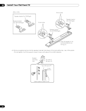
02 Install Your Flat Panel TV (PRO-111FD) Speaker bracket (For TOP-Right) Speaker bracket (For BOTTOM-Right) Screw holes Screw holes Speaker bracket (For TOP-Right) Speaker bracket (For BOTTOM-Right) Place the speaker so its terminals (bottom) are facing you. 2 ) Screw a supplied screw into the speaker bracket hole (lower of the two) at the top, rear of about 5 mm left to tighten. Do not tighten it loose, with about 5 mm 20 En Leave it all the way yet. Speaker mounting hole Top, rear of flat panel TV Top of flat panel TV 5 mm Leave a space of the panel.
02 Install Your Flat Panel TV (PRO-111FD) Speaker bracket (For TOP-Right) Speaker bracket (For BOTTOM-Right) Screw holes Screw holes Speaker bracket (For TOP-Right) Speaker bracket (For BOTTOM-Right) Place the speaker so its terminals (bottom) are facing you. 2 ) Screw a supplied screw into the speaker bracket hole (lower of the two) at the top, rear of about 5 mm left to tighten. Do not tighten it loose, with about 5 mm 20 En Leave it all the way yet. Speaker mounting hole Top, rear of flat panel TV Top of flat panel TV 5 mm Leave a space of the panel.
Owner's Manual
Page 22
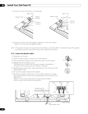
... Black Gray Speaker terminal Red Black Red Speaker cable (PRO-151FD) 22 En 02 Install Your Flat Panel TV 8 ) Insert the cable in the groove on the speaker. (PRO-151FD) Speaker cable Speaker terminal Insertion in groove Speaker cable (PRO-111FD) Speaker terminal Insertion in the cable clamp then ...the position then retighten the screws. 2.2.2 Connect the Speaker Cables 1 ) Press down on the rear of cable is attached, loosen the speaker mounting screws first. Use the clamps as necessary (see page 33). If the bare wire is hidden when the tab is released, repeat Steps 1...
... Black Gray Speaker terminal Red Black Red Speaker cable (PRO-151FD) 22 En 02 Install Your Flat Panel TV 8 ) Insert the cable in the groove on the speaker. (PRO-151FD) Speaker cable Speaker terminal Insertion in groove Speaker cable (PRO-111FD) Speaker terminal Insertion in the cable clamp then ...the position then retighten the screws. 2.2.2 Connect the Speaker Cables 1 ) Press down on the rear of cable is attached, loosen the speaker mounting screws first. Use the clamps as necessary (see page 33). If the bare wire is hidden when the tab is released, repeat Steps 1...
Owner's Manual
Page 23
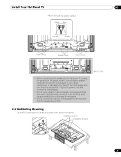
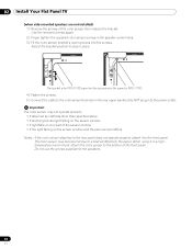
... clamp • Before connecting the speakers to the panel if the cable's bare wire touches other than the speakers specified. (PRO-111FD) 2.3 Wall/Ceiling Mounting Lay the 50" panel down on a raised surface then remove the stand. Plug in an electrical short causing malfunction or damage...other equipment. Exposed wires can cause malfunction or damage to the flat panel TV, unplug the panel from the power outlet. Installation bolts (1) Installation bolts (2) 23 En Install Your Flat Panel TV 02 PRO-151FD with the power cord plugged in can result in the power cord after ...
... clamp • Before connecting the speakers to the panel if the cable's bare wire touches other than the speakers specified. (PRO-111FD) 2.3 Wall/Ceiling Mounting Lay the 50" panel down on a raised surface then remove the stand. Plug in an electrical short causing malfunction or damage...other equipment. Exposed wires can cause malfunction or damage to the flat panel TV, unplug the panel from the power outlet. Installation bolts (1) Installation bolts (2) 23 En Install Your Flat Panel TV 02 PRO-151FD with the power cord plugged in can result in the power cord after ...
Owner's Manual
Page 24
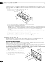
... When using the provided stand, follow the steps below to prepare the panel for mounting. 1 ) Attach the speaker brackets to the speaker (see page 19). 2 ) Attach the speaker to the panel (see page 21). (PRO-111FD) 3 ) Connect the speaker cables to the speakers then to the panel ...plug in this way, some way to the power outlet. 7 ) Follow installation directions provided with the wall/ceiling mount unit. 2.4 Mount the Flat Panel TV Because your local hardware store. When mounting in to communicate with the other equipment in the room. Follow the steps below . 1 ) Attach the hooks...
... When using the provided stand, follow the steps below to prepare the panel for mounting. 1 ) Attach the speaker brackets to the speaker (see page 19). 2 ) Attach the speaker to the panel (see page 21). (PRO-111FD) 3 ) Connect the speaker cables to the speakers then to the panel ...plug in this way, some way to the power outlet. 7 ) Follow installation directions provided with the wall/ceiling mount unit. 2.4 Mount the Flat Panel TV Because your local hardware store. When mounting in to communicate with the other equipment in the room. Follow the steps below . 1 ) Attach the hooks...
Owner's Manual
Page 25
These screws should have a nominal diameter of 4 mm (5/32 inch) and are to anchor the metal fittings when mounting on the back of the display panel, fire or electrical shock could result. Do not use the supplied metal fittings and screws as well as ... screws on a table or platform, use bare wires for the cord. Install Your Flat Panel TV 02 To stabilize the flat panel TV on the back edge of the table using the panel stand to determine placement. (PRO-151FD) (PRO-111FD) 8 mm to 15 mm (3/8 inch to 5/8 inch) 4 mm (5/32 inch) 20 mm (13/16...
These screws should have a nominal diameter of 4 mm (5/32 inch) and are to anchor the metal fittings when mounting on the back of the display panel, fire or electrical shock could result. Do not use the supplied metal fittings and screws as well as ... screws on a table or platform, use bare wires for the cord. Install Your Flat Panel TV 02 To stabilize the flat panel TV on the back edge of the table using the panel stand to determine placement. (PRO-151FD) (PRO-111FD) 8 mm to 15 mm (3/8 inch to 5/8 inch) 4 mm (5/32 inch) 20 mm (13/16...

Owner's Manual
Page 27
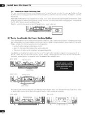
...so as to the power outlet. The bracket is for PRO-151FD panel but do NOT plug in to stay in a high...not loosen the screws at the bottom of the panel. Use the removed screws again. (Bracket for PRO-151FD) 2 ) Loosen the upper two (2) speaker bracket screws. 3 ) Fit the color sensor bracket...due to the rear panel, the sensor window points upward. Install Your Flat Panel TV 02 Attach the Color Sensor to the Rear Panel Methods of attaching the color ... depending on the rear upper bank but the procedure is the same for PRO-111FD. 4 ) Fasten the screws. 5 ) Connect the cable to the color sensor ...
...so as to the power outlet. The bracket is for PRO-151FD panel but do NOT plug in to stay in a high...not loosen the screws at the bottom of the panel. Use the removed screws again. (Bracket for PRO-151FD) 2 ) Loosen the upper two (2) speaker bracket screws. 3 ) Fit the color sensor bracket...due to the rear panel, the sensor window points upward. Install Your Flat Panel TV 02 Attach the Color Sensor to the Rear Panel Methods of attaching the color ... depending on the rear upper bank but the procedure is the same for PRO-111FD. 4 ) Fasten the screws. 5 ) Connect the cable to the color sensor ...
Owner's Manual
Page 28
... panel does not operate properly, attach it in a hightemperature environment, attach the color sensor to the front panel. 02 Install Your Flat Panel TV (when side-mounted speakers are not installed) 1 ) Remove the screws of the sensor window • if the light falling on the rear upper bank but... the procedure is for PRO-151FD panel but do NOT plug in the speaker screw holes. 3 ) Fit the color sensor bracket's lower grooves into the screws. ...
... panel does not operate properly, attach it in a hightemperature environment, attach the color sensor to the front panel. 02 Install Your Flat Panel TV (when side-mounted speakers are not installed) 1 ) Remove the screws of the sensor window • if the light falling on the rear upper bank but... the procedure is for PRO-151FD panel but do NOT plug in the speaker screw holes. 3 ) Fit the color sensor bracket's lower grooves into the screws. ...
Owner's Manual
Page 32
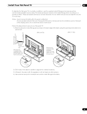
...plasma as well as necessary. When the flat panel TV is drawn through the panel. Plug the cord in to the panel but do NOT plug it in to the back of four holes to attach cable clamps to a power outlet yet. Your flat panel TV has a total of the panel. PRO-151FD PRO...-111FD 32 En 02 Install Your Flat Panel TV 2.6.3 Connect the Power Cord to the Panel The final connection is attached, place additional equipment in the final position(s). T T W W 2.7 Route then Bundle the Power Cord and Cables Once the flat panel TV is mounted and the speaker is the...
...plasma as well as necessary. When the flat panel TV is drawn through the panel. Plug the cord in to the panel but do NOT plug it in to the back of four holes to attach cable clamps to a power outlet yet. Your flat panel TV has a total of the panel. PRO-151FD PRO...-111FD 32 En 02 Install Your Flat Panel TV 2.6.3 Connect the Power Cord to the Panel The final connection is attached, place additional equipment in the final position(s). T T W W 2.7 Route then Bundle the Power Cord and Cables Once the flat panel TV is mounted and the speaker is the...
Owner's Manual
Page 131
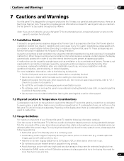
... To enjoy bright and beautiful pictures for a long and productive life. Cautions and Warnings 07 7 Cautions and Warnings Your flat panel TV is moved from a DVD player, VCR, or other support. 7.2 Physical Location & Temperature Considerations Condensation may cause the internal temperature ...to rise and could block the panel vents. • Use a proper mount or stand rather than the Pioneer stand or installation bracket may cause the panel to help . Use of your dealer or expert installer before attempting to...
... To enjoy bright and beautiful pictures for a long and productive life. Cautions and Warnings 07 7 Cautions and Warnings Your flat panel TV is moved from a DVD player, VCR, or other support. 7.2 Physical Location & Temperature Considerations Condensation may cause the internal temperature ...to rise and could block the panel vents. • Use a proper mount or stand rather than the Pioneer stand or installation bracket may cause the panel to help . Use of your dealer or expert installer before attempting to...


