Owner's Manual
Page 3
...into the power outlet. Product Name: Plasma Display System Model Number: PRO-1540HD/PRO-1140HD/PRO-940HD Product Category: Class B Personal Computers & Peripherals Responsible Party Name: PIONEER ELECTRONICS SERVICE, INC. Reorient or relocate the receiving antenna. - However, the Plasma Display System will expose you to lead...with the limits for help. Increase the separation between the equipment and receiver. - Consult the dealer or an experienced radio/TV technician for a Class B digital device, pursuant to Part 15 of California and other reproductive harm. THE SERIAL NUMBER FOR...
...into the power outlet. Product Name: Plasma Display System Model Number: PRO-1540HD/PRO-1140HD/PRO-940HD Product Category: Class B Personal Computers & Peripherals Responsible Party Name: PIONEER ELECTRONICS SERVICE, INC. Reorient or relocate the receiving antenna. - However, the Plasma Display System will expose you to lead...with the limits for help. Increase the separation between the equipment and receiver. - Consult the dealer or an experienced radio/TV technician for a Class B digital device, pursuant to Part 15 of California and other reproductive harm. THE SERIAL NUMBER FOR...
Owner's Manual
Page 4
... or regions, the shape of the power plug and power outlet may sometimes differ from Falling Over 21 Attaching/detaching the PIONEER stand (for PRO-940HD only 22 08 Menu Setup Menu Configuration 36 AV mode menus 36 PC mode menus 36 Menu operations 36 Cable connections... for the PRO-1140HD unless otherwise specified. 01 Important User Guidance Information 02 Safety Precautions 03 Supplied Accessories Using the POD service 30 Using the multiscreen functions 30 Splitting the screen 30 Freezing images 31 04 Part Names Plasma Display 13 Remote control unit 19 07 TV Guide On ...
... or regions, the shape of the power plug and power outlet may sometimes differ from Falling Over 21 Attaching/detaching the PIONEER stand (for PRO-940HD only 22 08 Menu Setup Menu Configuration 36 AV mode menus 36 PC mode menus 36 Menu operations 36 Cable connections... for the PRO-1140HD unless otherwise specified. 01 Important User Guidance Information 02 Safety Precautions 03 Supplied Accessories Using the POD service 30 Using the multiscreen functions 30 Splitting the screen 30 Freezing images 31 04 Part Names Plasma Display 13 Remote control unit 19 07 TV Guide On ...
Owner's Manual
Page 7
...still picture mode from a TV, VCR, DVD player or any still image, it is best to view a normal moving image was purchased. To avoid malfunction and overheating when installing, make sure that the vents on your Pioneer Plasma Display Panel for an equal...Important User Guidance Information English In order to obtain maximum enjoyment from this Pioneer PureVision PRO-1540HD/PRO-1140HD/PRO-940HD Plasma Display Panel, please first read and follow the usage guidelines below. With the Pioneer PureVision PRO-1540HD/PRO-1140HD/PRO940HD, you can be assured of time. • After playing ...
...still picture mode from a TV, VCR, DVD player or any still image, it is best to view a normal moving image was purchased. To avoid malfunction and overheating when installing, make sure that the vents on your Pioneer Plasma Display Panel for an equal...Important User Guidance Information English In order to obtain maximum enjoyment from this Pioneer PureVision PRO-1540HD/PRO-1140HD/PRO-940HD Plasma Display Panel, please first read and follow the usage guidelines below. With the Pioneer PureVision PRO-1540HD/PRO-1140HD/PRO940HD, you can be assured of time. • After playing ...
Owner's Manual
Page 10
... in the operating instructions Do not touch the controls other dangerous conditions. Removing covers can break the glass. Improper adjustments can block the vents. PRO-1140HD - 34.3 kg (75.7 lbs.) - Do not place the product on a wall or ceiling, install the panel according to the panel.... an unstable base can cause electrical shock and/or short internal parts. Overloading can cause overheating and/or shorten the life of each Plasma Display Panel is damaged • liquid spilled or objects fallen into the products. Do not use liquid or aerosol cleaners. •...
... in the operating instructions Do not touch the controls other dangerous conditions. Removing covers can break the glass. Improper adjustments can block the vents. PRO-1140HD - 34.3 kg (75.7 lbs.) - Do not place the product on a wall or ceiling, install the panel according to the panel.... an unstable base can cause electrical shock and/or short internal parts. Overloading can cause overheating and/or shorten the life of each Plasma Display Panel is damaged • liquid spilled or objects fallen into the products. Do not use liquid or aerosol cleaners. •...
Owner's Manual
Page 11
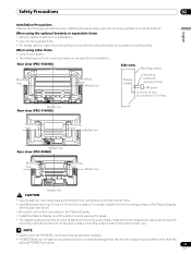
...Side view Mounting surface Mounting hole Mounting hole Median line Plasma Display Mounting bracket (or equivalent item) M8 screw 12 mm to 18 mm (0.5 inches to 0.7 inches) Median line Rear view (PRO-1140HD) Mounting hole Mounting hole Median line Median line Rear view (PRO-940HD) Mounting hole Mounting hole Median line Median line ... details, see the instruction manual that results from the mounting surface of standard mounting screw holes. When using mounting items other than the optional PIONEER products. 11 En When using optional mounting methods such as the bracket.
...Side view Mounting surface Mounting hole Mounting hole Median line Plasma Display Mounting bracket (or equivalent item) M8 screw 12 mm to 18 mm (0.5 inches to 0.7 inches) Median line Rear view (PRO-1140HD) Mounting hole Mounting hole Median line Median line Rear view (PRO-940HD) Mounting hole Mounting hole Median line Median line ... details, see the instruction manual that results from the mounting surface of standard mounting screw holes. When using mounting items other than the optional PIONEER products. 11 En When using optional mounting methods such as the bracket.
Owner's Manual
Page 12
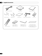
03 Supplied Accessories Supplied Accessories Power cord (2 m/6.6 feet) Cleaning cloth Operating instructions Speed clamp × 3 Bead band × 3 Warranty card G-LINK cable (3 m/9.8 feet) Ferrite core Remote control unit AA size battery x 2 (Alkaline battery for remote control unit) Hexagonal wrench x 1 (Diagonal size: 6 mm) (for PRO-940HD only) Terminal position sheet (for use when mounting the Plasma Display on the wall) (for PRO-1540HD only) 12 En
03 Supplied Accessories Supplied Accessories Power cord (2 m/6.6 feet) Cleaning cloth Operating instructions Speed clamp × 3 Bead band × 3 Warranty card G-LINK cable (3 m/9.8 feet) Ferrite core Remote control unit AA size battery x 2 (Alkaline battery for remote control unit) Hexagonal wrench x 1 (Diagonal size: 6 mm) (for PRO-940HD only) Terminal position sheet (for use when mounting the Plasma Display on the wall) (for PRO-1540HD only) 12 En

Owner's Manual
Page 13
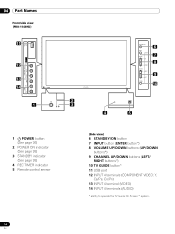
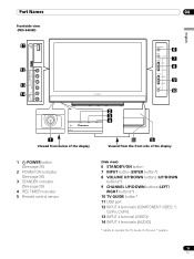
Part Names Part Names Plasma Display Front/side view (PRO-1540HD) 11 12 13 14 1 1 a POWER button (See page 26) 2 POWER ON indicator (See page 26) 3 STANDBY indicator (See page 26) 4 REC TIMER indicator 5 Remote ... 6 7 8 9 10 2 3 4 5 (Side view) 6 STANDBY/ON button 7 INPUT button (ENTER button*) 8 VOLUME UP/DOWN buttons (UP/DOWN buttons*) 9 CHANNEL UP/DOWN buttons (LEFT/ RIGHT buttons*) 10 TV GUIDE button* 11 USB port 12 INPUT 4 terminals (COMPONENT VIDEO: Y, CB/PB, CR/PR) 13 INPUT 4 terminal (VIDEO) 14 INPUT 4 terminals (AUDIO) * ability to operate...
Part Names Part Names Plasma Display Front/side view (PRO-1540HD) 11 12 13 14 1 1 a POWER button (See page 26) 2 POWER ON indicator (See page 26) 3 STANDBY indicator (See page 26) 4 REC TIMER indicator 5 Remote ... 6 7 8 9 10 2 3 4 5 (Side view) 6 STANDBY/ON button 7 INPUT button (ENTER button*) 8 VOLUME UP/DOWN buttons (UP/DOWN buttons*) 9 CHANNEL UP/DOWN buttons (LEFT/ RIGHT buttons*) 10 TV GUIDE button* 11 USB port 12 INPUT 4 terminals (COMPONENT VIDEO: Y, CB/PB, CR/PR) 13 INPUT 4 terminal (VIDEO) 14 INPUT 4 terminals (AUDIO) * ability to operate...
Owner's Manual
Page 14
04 Part Names Front/side view (PRO-1140HD) 11 12 13 14 1 1 a POWER button (See page 26) 2 POWER ON indicator (See page 26) 3 STANDBY indicator (See page 26) 4 REC TIMER indicator 5 Remote control sensor 6 7 8 9 10 2 3 4 5 (Side view) 6 STANDBY/ON button 7 INPUT button (ENTER button*) 8 VOLUME UP/DOWN buttons (UP/DOWN buttons*) 9 CHANNEL UP/DOWN buttons (LEFT/ RIGHT buttons*) 10 TV GUIDE button* 11 USB port 12 INPUT 4 terminals (COMPONENT VIDEO: Y, CB/PB, CR/PR) 13 INPUT 4 terminal (VIDEO) 14 INPUT 4 terminals (AUDIO) * ability to operate the TV Guide On Screen™ system. 14 En
04 Part Names Front/side view (PRO-1140HD) 11 12 13 14 1 1 a POWER button (See page 26) 2 POWER ON indicator (See page 26) 3 STANDBY indicator (See page 26) 4 REC TIMER indicator 5 Remote control sensor 6 7 8 9 10 2 3 4 5 (Side view) 6 STANDBY/ON button 7 INPUT button (ENTER button*) 8 VOLUME UP/DOWN buttons (UP/DOWN buttons*) 9 CHANNEL UP/DOWN buttons (LEFT/ RIGHT buttons*) 10 TV GUIDE button* 11 USB port 12 INPUT 4 terminals (COMPONENT VIDEO: Y, CB/PB, CR/PR) 13 INPUT 4 terminal (VIDEO) 14 INPUT 4 terminals (AUDIO) * ability to operate the TV Guide On Screen™ system. 14 En
Owner's Manual
Page 15
Part Names Front/side view (PRO-940HD) 11 12 13 14 04 6 7 8 9 10 2 3 4 English 1 Viewed from below of the display 5 Viewed from the front side of the display 1 a POWER button (See ... sensor (Side view) 6 STANDBY/ON button 7 INPUT button (ENTER button*) 8 VOLUME UP/DOWN buttons (UP/DOWN buttons*) 9 CHANNEL UP/DOWN buttons (LEFT/ RIGHT buttons*) 10 TV GUIDE button* 11 USB port 12 INPUT 4 terminals (COMPONENT VIDEO: Y, CB/PB, CR/PR) 13 INPUT 4 terminal (VIDEO) 14 INPUT 4 terminals (AUDIO) * ability to operate...
Part Names Front/side view (PRO-940HD) 11 12 13 14 04 6 7 8 9 10 2 3 4 English 1 Viewed from below of the display 5 Viewed from the front side of the display 1 a POWER button (See ... sensor (Side view) 6 STANDBY/ON button 7 INPUT button (ENTER button*) 8 VOLUME UP/DOWN buttons (UP/DOWN buttons*) 9 CHANNEL UP/DOWN buttons (LEFT/ RIGHT buttons*) 10 TV GUIDE button* 11 USB port 12 INPUT 4 terminals (COMPONENT VIDEO: Y, CB/PB, CR/PR) 13 INPUT 4 terminal (VIDEO) 14 INPUT 4 terminals (AUDIO) * ability to operate...
Owner's Manual
Page 16
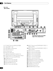
04 Part Names Rear view (PRO-1540HD) 17 18 21 22 23 12 3 45 11 12 13 14 15 16 19 20 24 25 6 7 26 27 28 8 9 10 (Terminals located on ...
04 Part Names Rear view (PRO-1540HD) 17 18 21 22 23 12 3 45 11 12 13 14 15 16 19 20 24 25 6 7 26 27 28 8 9 10 (Terminals located on ...

Owner's Manual
Page 17
Part Names 04 Rear view (PRO-1140HD) English 17 18 21 22 23 12 3 45 11 12 13 14 15 16 19 20 24 25 6 26 27 28 7 8 9 10 (Terminals located on ...
Part Names 04 Rear view (PRO-1140HD) English 17 18 21 22 23 12 3 45 11 12 13 14 15 16 19 20 24 25 6 26 27 28 7 8 9 10 (Terminals located on ...
Owner's Manual
Page 18
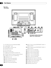
04 Part Names Rear view (PRO-940HD) 17 18 21 22 23 11 12 13 14 15 16 19 20 24 25 6 26 27 12 3 45 7 8 9 10 (Terminals located on the ...
04 Part Names Rear view (PRO-940HD) 17 18 21 22 23 11 12 13 14 15 16 19 20 24 25 6 26 27 12 3 45 7 8 9 10 (Terminals located on the ...

Owner's Manual
Page 20
... held upright. NOTE • Allow enough space around the installed Plasma Display Panel to the instruction manual supplied with the speaker. Therefore, at all times. 20 En Using the optional PIONEER stand (for PRO-1540HD and PRO-1140HD) • For details on a rack, etc., someone help... you when moving or installing the panel. 05 Preparation Preparation Installing the Plasma Display (PRO-1140HD) Over 50 cm (19 11/16 inches) Over 10 cm ...
... held upright. NOTE • Allow enough space around the installed Plasma Display Panel to the instruction manual supplied with the speaker. Therefore, at all times. 20 En Using the optional PIONEER stand (for PRO-1540HD and PRO-1140HD) • For details on a rack, etc., someone help... you when moving or installing the panel. 05 Preparation Preparation Installing the Plasma Display (PRO-1140HD) Over 50 cm (19 11/16 inches) Over 10 cm ...

Owner's Manual
Page 22
...10113; for reattaching the glass components. 05 Preparation Attaching/detaching the PIONEER stand (for PRO-940HD only) The PRO-940HD comes with more people are required to insert the stand supports into any part of the Plasma Display . 2 Bolt the Plasma Display to the stand at a later date. • Insert... the holes vertically. 22 • Do not tighten them with the PIONEER table top stand attached. The method for attaching/detaching the stand varies depending on a flat, stable location to the Plasma Display at the points indicated by detaching the stand. stand to avoid ...
...10113; for reattaching the glass components. 05 Preparation Attaching/detaching the PIONEER stand (for PRO-940HD only) The PRO-940HD comes with more people are required to insert the stand supports into any part of the Plasma Display . 2 Bolt the Plasma Display to the stand at a later date. • Insert... the holes vertically. 22 • Do not tighten them with the PIONEER table top stand attached. The method for attaching/detaching the stand varies depending on a flat, stable location to the Plasma Display at the points indicated by detaching the stand. stand to avoid ...

Owner's Manual
Page 24
... or cause chemical leakage in old batteries. • Do not leave dead batteries in the unit are weak. Allowed operation range of the Plasma Display. Dead batteries leak chemicals. Cautions regarding batteries • The remote control unit cannot operate the system if the batteries in the remote ...infrared remote control such as a VCR may not work properly if the panel's remote sensor window is in the lower right corner on the PRO-940HD, the sensor is under direct sunlight, the unit may deform. • The remote control may receive scrambled or incomplete commands from ...
... or cause chemical leakage in old batteries. • Do not leave dead batteries in the unit are weak. Allowed operation range of the Plasma Display. Dead batteries leak chemicals. Cautions regarding batteries • The remote control unit cannot operate the system if the batteries in the remote ...infrared remote control such as a VCR may not work properly if the panel's remote sensor window is in the lower right corner on the PRO-940HD, the sensor is under direct sunlight, the unit may deform. • The remote control may receive scrambled or incomplete commands from ...

Owner's Manual
Page 25
...the main unit Attach the speed clamps using any of the 4 holes you prefer (50 inches, 3 holes: 42 inches, 2 holes) marked with a ground terminal is used for a long period of time. for PRO-1540HD for PRO-1140HD for safety reasons. The clamp may deteriorate over time and become damaged if removed. 2...result in place. Always connect the power cord to lock the clamp. Please attach them carefully. Routing cables When the speakers are connected. Plasma Display (rear view) AC IN terminal is located on the sides Rear view NOTE • Always turn the panel's power OFF when ...
...the main unit Attach the speed clamps using any of the 4 holes you prefer (50 inches, 3 holes: 42 inches, 2 holes) marked with a ground terminal is used for a long period of time. for PRO-1540HD for PRO-1140HD for safety reasons. The clamp may deteriorate over time and become damaged if removed. 2...result in place. Always connect the power cord to lock the clamp. Please attach them carefully. Routing cables When the speakers are connected. Plasma Display (rear view) AC IN terminal is located on the sides Rear view NOTE • Always turn the panel's power OFF when ...

Owner's Manual
Page 26
...Standby. CAUTION • If the POWER ON and STANDBY indicators are off the power (to Standby) 1 Press TV a on the remote control unit or STANDBY/ON on the Plasma Display. • The system enters the standby mode and the image on the screen disappears. • The ... the remote control unit or STANDBY/ON on the Plasma Display to use this system for the Standby indicator to automatically receive digital TV program information while in Standby. Plasma Display (PRO-1540HD) POWER button POWER ON indicator STANDBY indicator (PRO-1140HD) POWER button Turning off , the system cannot be ...
...Standby. CAUTION • If the POWER ON and STANDBY indicators are off the power (to Standby) 1 Press TV a on the remote control unit or STANDBY/ON on the Plasma Display. • The system enters the standby mode and the image on the screen disappears. • The ... the remote control unit or STANDBY/ON on the Plasma Display to use this system for the Standby indicator to automatically receive digital TV program information while in Standby. Plasma Display (PRO-1540HD) POWER button POWER ON indicator STANDBY indicator (PRO-1140HD) POWER button Turning off , the system cannot be ...
Owner's Manual
Page 36
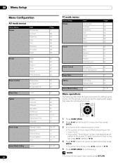
08 Menu Setup Menu Setup Menu Configuration AV mode menus Home Menu Picture Item AV Selection Contrast Brightness Color Tint Sharpness Pro Adjust Reset Sound Treble Bass Balance Reset FOCUS Front Surround Power Control Energy Save No Signal off No Operation off Sleep Timer Option Position Auto ...
08 Menu Setup Menu Setup Menu Configuration AV mode menus Home Menu Picture Item AV Selection Contrast Brightness Color Tint Sharpness Pro Adjust Reset Sound Treble Bass Balance Reset FOCUS Front Surround Power Control Energy Save No Signal off No Operation off Sleep Timer Option Position Auto ...

Owner's Manual
Page 39
...down the password and keep it somewhere safe. Tuner Setup 09 English 10 Press HOME MENU to exit the menu. PRO-1540HD/PRO-1140HD/PRO-940HD Your password No.: If you forget the password When the message "Enter your 4-digit password using the number... TV Ratings TV-None TV-Y TV-Y7 TV-G TV-PG Blocked TV Ratings xxxxxxxxxxxxxxxxxxxxx xxxxxxxxxxxxxxxxxxxxx xxxxxxxxxxxxxxxxxxxxx Home Menu Exit • The password entry screen appears. 6 Enter your Password" is switched. • A lock icon appears beside the blocked rating. • The Plasma Display ships with all ratings ...
...down the password and keep it somewhere safe. Tuner Setup 09 English 10 Press HOME MENU to exit the menu. PRO-1540HD/PRO-1140HD/PRO-940HD Your password No.: If you forget the password When the message "Enter your 4-digit password using the number... TV Ratings TV-None TV-Y TV-Y7 TV-G TV-PG Blocked TV Ratings xxxxxxxxxxxxxxxxxxxxx xxxxxxxxxxxxxxxxxxxxx xxxxxxxxxxxxxxxxxxxxx Home Menu Exit • The password entry screen appears. 6 Enter your Password" is switched. • A lock icon appears beside the blocked rating. • The Plasma Display ships with all ratings ...
Owner's Manual
Page 58
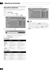
... adjustment screen is displayed, you can also press / to change the item to be adjusted. ( / then ENTER) Picture AV Selection Contrast Brightness Color Tint Sharpness Pro Adjust Reset STANDARD 40 0 0 0 0 4 Select the desired level. ( / ) Contrast 40 For PC source, the following screen appears: Picture AV Selection Contrast Brightness Red Green Blue...
... adjustment screen is displayed, you can also press / to change the item to be adjusted. ( / then ENTER) Picture AV Selection Contrast Brightness Color Tint Sharpness Pro Adjust Reset STANDARD 40 0 0 0 0 4 Select the desired level. ( / ) Contrast 40 For PC source, the following screen appears: Picture AV Selection Contrast Brightness Red Green Blue...


