

Leaflet
Page 1
... • Motion Adaptive De-interlacing for indoor public display applications. The high class scaler, advanced digital video processing and the latest plasma technology guarantee optimal display of over 60.000 hours Philips plasma monitor 42" WVGA BDS4223V Multi-Purpose Public Display Solution 42" Wide VGA Plasma Monitor State of the art, cost effective plasma monitor specially designed for razor sharp images • PiP allows watching a second source simultaneously Lower total...
... • Motion Adaptive De-interlacing for indoor public display applications. The high class scaler, advanced digital video processing and the latest plasma technology guarantee optimal display of over 60.000 hours Philips plasma monitor 42" WVGA BDS4223V Multi-Purpose Public Display Solution 42" Wide VGA Plasma Monitor State of the art, cost effective plasma monitor specially designed for razor sharp images • PiP allows watching a second source simultaneously Lower total...
Leaflet
Page 2
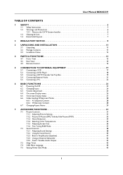
...; Network controllable: RS232 • User convenience: On-screen Display • Monitor Controls: Left/Right, Power On/Off, Up/ Down, Source Select, Menu (OK), Volume control • OSD Languages: English, French, Spanish • Built-in Audio: Built-in amplifier and 5 Watts RMSx2 stereo speakers • Screen saving functions: Full white, pixel shift • Regulatory approvals: CE Mark, FCC-B, UL, CSA Power • Consumption (On mode): 350 Watts (color bar pattern) • Power supply: 100...
...; Network controllable: RS232 • User convenience: On-screen Display • Monitor Controls: Left/Right, Power On/Off, Up/ Down, Source Select, Menu (OK), Volume control • OSD Languages: English, French, Spanish • Built-in Audio: Built-in amplifier and 5 Watts RMSx2 stereo speakers • Screen saving functions: Full white, pixel shift • Regulatory approvals: CE Mark, FCC-B, UL, CSA Power • Consumption (On mode): 350 Watts (color bar pattern) • Power supply: 100...
User manual
Page 3
...3.1 Unpacking 11 3.2 Package Contents 11 3.3 Installation Notes 12 4 PARTS & FUNCTIONS 13 4.1 Front View 13 4.2 Rear View 14 4.3 Remote Control 15 5 CONNECTION TO EXTERNAL EQUIPMENT 17 5.1 Connecting a VCR 17 5.2 Connecting a DVD Player 18 5.3 Connecting a HDTV Decoder Set-Top Box 19 5.4 Connecting External Audio 21 5.5 Connecting a PC 22 6 BASIC FUNCTIONS 23 6.1 Powering On/Off 23 6.2 Changing Inputs 24 6.3 Volume Adjustment 25 6.4 On-screen Display menu 26 6.5 On-Screen Display Status 27 6.6 Understanding Widescreen Modes 28 6.6.1 4:3 (Square) Content 28 6.6.2 Widescreen...
...3.1 Unpacking 11 3.2 Package Contents 11 3.3 Installation Notes 12 4 PARTS & FUNCTIONS 13 4.1 Front View 13 4.2 Rear View 14 4.3 Remote Control 15 5 CONNECTION TO EXTERNAL EQUIPMENT 17 5.1 Connecting a VCR 17 5.2 Connecting a DVD Player 18 5.3 Connecting a HDTV Decoder Set-Top Box 19 5.4 Connecting External Audio 21 5.5 Connecting a PC 22 6 BASIC FUNCTIONS 23 6.1 Powering On/Off 23 6.2 Changing Inputs 24 6.3 Volume Adjustment 25 6.4 On-screen Display menu 26 6.5 On-Screen Display Status 27 6.6 Understanding Widescreen Modes 28 6.6.1 4:3 (Square) Content 28 6.6.2 Widescreen...
User manual
Page 5
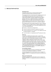
.... ■ Do not remove cover, to insert the plug into your signal wire connections and reconnect the display to the electric outlet. ■ Only use attachments/accessories specified by a qualified technician to restore the unit to qualified service personel only. ■ Unauthorized modification of this apparatus near any of available power is a safety feature. Install in accordance with a slightly...
.... ■ Do not remove cover, to insert the plug into your signal wire connections and reconnect the display to the electric outlet. ■ Only use attachments/accessories specified by a qualified technician to restore the unit to qualified service personel only. ■ Unauthorized modification of this apparatus near any of available power is a safety feature. Install in accordance with a slightly...
User manual
Page 11
... display is connected. ■ Consult the dealer or an experienced radio/TV technician for the product. Warning User must use shielded signal interface cables to provide reasonable protection against harmful interference in a particular installation. It may cause harmful interference to which the receiver is a detachable power supply cord with NEMA configuration 6015P type (tandem blades) plug cap. 2. IC Compliance Notice This Class B digital...
... display is connected. ■ Consult the dealer or an experienced radio/TV technician for the product. Warning User must use shielded signal interface cables to provide reasonable protection against harmful interference in a particular installation. It may cause harmful interference to which the receiver is a detachable power supply cord with NEMA configuration 6015P type (tandem blades) plug cap. 2. IC Compliance Notice This Class B digital...
User manual
Page 16
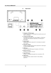
... video signals from external sources such VCRs or DVD players. 2. RGB Input Connect to an external audio amplifier. 4. Composite / S-Video Inputs Connect Composite or S-Video signals from a set top box or PC. 8. Component Video Inputs Auto-detecting component video inputs (Y/Pb/Pr or Y/Cb/Cr) for connecting to RGB (VGA) output of a DVD player or Set-Top Box. 3. User Manual BDS4223V 4.2 REAR VIEW MAIN POWER 8 2 4 - 6 7 5 3 1 1. Digital DVI Input Connects to the component output jacks of computer or Set-Top box. 6. RS-232 Connector Connect to a computer serial port...
... video signals from external sources such VCRs or DVD players. 2. RGB Input Connect to an external audio amplifier. 4. Composite / S-Video Inputs Connect Composite or S-Video signals from a set top box or PC. 8. Component Video Inputs Auto-detecting component video inputs (Y/Pb/Pr or Y/Cb/Cr) for connecting to RGB (VGA) output of a DVD player or Set-Top Box. 3. User Manual BDS4223V 4.2 REAR VIEW MAIN POWER 8 2 4 - 6 7 5 3 1 1. Digital DVI Input Connects to the component output jacks of computer or Set-Top box. 6. RS-232 Connector Connect to a computer serial port...
User manual
Page 17
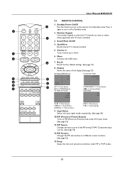
Number Keypad Use number keypad to select the TV channel you want to 4 different corner locations. (See page 33) 13. Volume +/- 14 Turns volume up or down. 6. Display Shows the status of the PIP among TV/AV Component input sources. (See page 33) 12. Input Select Selects the input signal modes sequentially. (See page 24) 10. Recall Recalls Factory default settings. (See page 31) 8. PIP Source Changes the input source of the display (See page 27): AV Mode (PIP/POP...
Number Keypad Use number keypad to select the TV channel you want to 4 different corner locations. (See page 33) 13. Volume +/- 14 Turns volume up or down. 6. Display Shows the status of the PIP among TV/AV Component input sources. (See page 33) 12. Input Select Selects the input signal modes sequentially. (See page 24) 10. Recall Recalls Factory default settings. (See page 31) 8. PIP Source Changes the input source of the display (See page 27): AV Mode (PIP/POP...

User manual
Page 19
... L audio-in jacks located next to connect your VCR. 17 CONNECTION TO EXTERNAL EQUIPMENT S-Video (4-Pin-DIN) Audio L/R (2xRCA cables) VCR 5.1 CONNECTING A VCR Using S-Video Input 1 Connect the S-Video (4-pin DIN) connector from the VCR to the yellow "VIDEO 1" connector. Note: There are two sets of monitor. 2 Connect the red (R) and white (L) audio jacks from the VCR to the R and L audio-in jacks located next to the "S-VIDEO" input on the back of composite inputs provided. User Manual BDS4223V 5.
... L audio-in jacks located next to connect your VCR. 17 CONNECTION TO EXTERNAL EQUIPMENT S-Video (4-Pin-DIN) Audio L/R (2xRCA cables) VCR 5.1 CONNECTING A VCR Using S-Video Input 1 Connect the S-Video (4-pin DIN) connector from the VCR to the yellow "VIDEO 1" connector. Note: There are two sets of monitor. 2 Connect the red (R) and white (L) audio jacks from the VCR to the R and L audio-in jacks located next to the "S-VIDEO" input on the back of composite inputs provided. User Manual BDS4223V 5.

User manual
Page 20
...: There are two sets of S-Video inputs provided. User Manual BDS4223V Audio L/R Component Video (2xRCA cables) (3xRCA cable) DVD PLAYER S-Video (4-Pin-DIN) Audio L/R (2xRCA cables) DVD PLAYER Video (RCA cable) Audio L/R (2xRCA cables) DVD PLAYER 5.2 CONNECTING A DVD PLAYER Using Component Video Input 1 Connect the green-colored (labeled as "Y") jack from the DVD player to the green-colored "Y1" jack of the monitor. 2 Connect the red-colored (labeled as "PR" or "CR") jack from the DVD player to the red-colored "PR1/CR1" jack of the monitor. 3 Connect the blue-colored (labeled as "PB...
...: There are two sets of S-Video inputs provided. User Manual BDS4223V Audio L/R Component Video (2xRCA cables) (3xRCA cable) DVD PLAYER S-Video (4-Pin-DIN) Audio L/R (2xRCA cables) DVD PLAYER Video (RCA cable) Audio L/R (2xRCA cables) DVD PLAYER 5.2 CONNECTING A DVD PLAYER Using Component Video Input 1 Connect the green-colored (labeled as "Y") jack from the DVD player to the green-colored "Y1" jack of the monitor. 2 Connect the red-colored (labeled as "PR" or "CR") jack from the DVD player to the red-colored "PR1/CR1" jack of the monitor. 3 Connect the blue-colored (labeled as "PB...

User manual
Page 24
... screens on your computer's video output settings. 4 Set the "Screen Resolution" settings to 1024x768 PIXELS. 5 For COLOR QUALITY, select 24 BIT COLOR (might also be connected. See page 51 for a typical Windows-based computer are using Display Data Channel (DDC) protocols. If you have a PC that is conform the VESA Plug and Play standaard. User Manual BDS4223V 5.5 CONNECTING A PC Using RGB or DVI Video Input 1 For most cases. 1 Go to the Window's CONTROL PANEL by clicking START, SETTINGS, CONTROL PANEL. => The CONTROL PANEL...
... screens on your computer's video output settings. 4 Set the "Screen Resolution" settings to 1024x768 PIXELS. 5 For COLOR QUALITY, select 24 BIT COLOR (might also be connected. See page 51 for a typical Windows-based computer are using Display Data Channel (DDC) protocols. If you have a PC that is conform the VESA Plug and Play standaard. User Manual BDS4223V 5.5 CONNECTING A PC Using RGB or DVI Video Input 1 For most cases. 1 Go to the Window's CONTROL PANEL by clicking START, SETTINGS, CONTROL PANEL. => The CONTROL PANEL...

User manual
Page 27
Using MUTE 1 If you would like to silence the volume on the monitor panel or remote control. 2 To turn up sound volume, press VOLUME + on a temporary basis, simply press the MUTE key to silence the volume. User Manual BDS4223V 6.3 VOLUME ADJUSTMENT Using Front Panel or Remote Control 1 To turn down sound volume, press VOLUME - When the monitor's volume is muted, the monitor will display MUTE on the monitor panel or remote control. on the upper right corner of the screen. 2 To disengage the mute mode, simply press the MUTE key again or the volume buttons. 25
Using MUTE 1 If you would like to silence the volume on the monitor panel or remote control. 2 To turn up sound volume, press VOLUME + on a temporary basis, simply press the MUTE key to silence the volume. User Manual BDS4223V 6.3 VOLUME ADJUSTMENT Using Front Panel or Remote Control 1 To turn down sound volume, press VOLUME - When the monitor's volume is muted, the monitor will display MUTE on the monitor panel or remote control. on the upper right corner of the screen. 2 To disengage the mute mode, simply press the MUTE key again or the volume buttons. 25
User manual
Page 28
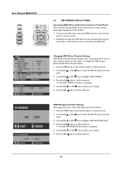
... confirm selection. User Manual BDS4223V Hi OSD OSD 10 6.4 ON-SCREEN DISPLAY MENU Accessing OSD Menu via Remote Control or Front Panel The On-Screen Display (OSD) menu allows access to setup various parameters equipped with this display. 1 To access the OSD menu, press the MENU button on the monitor panel or remote control. 2 Navigation through the OSD Menu can be accomplished using the arrow keys on the screen. Changing OSD Menu Timeout Setting OSD Menu will automatically disappear...
... confirm selection. User Manual BDS4223V Hi OSD OSD 10 6.4 ON-SCREEN DISPLAY MENU Accessing OSD Menu via Remote Control or Front Panel The On-Screen Display (OSD) menu allows access to setup various parameters equipped with this display. 1 To access the OSD menu, press the MENU button on the monitor panel or remote control. 2 Navigation through the OSD Menu can be accomplished using the arrow keys on the screen. Changing OSD Menu Timeout Setting OSD Menu will automatically disappear...

User manual
Page 33
... the PICTURE menu is displayed. 6 Use the ADJ or ADJ key to change the setting, changes in the picture are available in the video picture. 7 After achieving desired setting, press the SEL key to confirm setting and return to confirm selection. =>A small display window appears. Notes: ● H-Position, H-Size, V-Position, V-Size adjustments are only available in RGB and Component video input modes. ● To restore picture settings to factory default, simply press the RECALL...
... the PICTURE menu is displayed. 6 Use the ADJ or ADJ key to change the setting, changes in the picture are available in the video picture. 7 After achieving desired setting, press the SEL key to confirm setting and return to confirm selection. =>A small display window appears. Notes: ● H-Position, H-Size, V-Position, V-Size adjustments are only available in RGB and Component video input modes. ● To restore picture settings to factory default, simply press the RECALL...

User manual
Page 35
... change the sub-picture's input source 2 Press the SOURCE key repeatedly to POP mode. 3 Press the PIP key sequentially will denote the input signal source for main picture (large screen) and the sub-picture (small screen) displayed. Turning on PIP or POP Mode 1 Press the PIP key once on the remote control to activate in PIP mode. 2 Press the PIP again to switch to cycle through all available inputs for Sub-Picture Once the PIP or POP mode is turned...
... change the sub-picture's input source 2 Press the SOURCE key repeatedly to POP mode. 3 Press the PIP key sequentially will denote the input signal source for main picture (large screen) and the sub-picture (small screen) displayed. Turning on PIP or POP Mode 1 Press the PIP key once on the remote control to activate in PIP mode. 2 Press the PIP again to switch to cycle through all available inputs for Sub-Picture Once the PIP or POP mode is turned...

User manual
Page 40
User Manual BDS4223V 7.2 SOUND CONTROLS 7.2.1 ADJUSTING SOUND SETTINGS Using OSD Menu Various sound adjustments can be set using the Sound Adjustment OSD menu. 1 Press the MENU button on the monitor panel or remote control. 2 Use the SEL or SEL key to select the SOUND option from the menu. 3 Press the ADJ key to confirm the selection. => Various options are available in the SOUND menu. 4 Use the SEL or SEL key to select the option to change. 5 Press the ADJ key to...
User Manual BDS4223V 7.2 SOUND CONTROLS 7.2.1 ADJUSTING SOUND SETTINGS Using OSD Menu Various sound adjustments can be set using the Sound Adjustment OSD menu. 1 Press the MENU button on the monitor panel or remote control. 2 Use the SEL or SEL key to select the SOUND option from the menu. 3 Press the ADJ key to confirm the selection. => Various options are available in the SOUND menu. 4 Use the SEL or SEL key to select the option to change. 5 Press the ADJ key to...

User manual
Page 44
... fixed audio outputs. 1 Press the MENU button on the back of output this monitor outputs from the subwoofer's input to the previous menu. 42 User Manual BDS4223V 7.2.4 USING AN EXTERNAL SUBWOOFER Connecting a Subwoofer This monitor is affected by FIXED or VARIABLE audio output setting and works in the SOUND menu. 4 Use the SEL or SEL key to select the AUDIO OUTPUT option. 5 Press the ADJ key to confirm selection. => The AUDIO OUTPUT menu appears. 6 Use the ADJ or ADJ key to change the setting...
... fixed audio outputs. 1 Press the MENU button on the back of output this monitor outputs from the subwoofer's input to the previous menu. 42 User Manual BDS4223V 7.2.4 USING AN EXTERNAL SUBWOOFER Connecting a Subwoofer This monitor is affected by FIXED or VARIABLE audio output setting and works in the SOUND menu. 4 Use the SEL or SEL key to select the AUDIO OUTPUT option. 5 Press the ADJ key to confirm selection. => The AUDIO OUTPUT menu appears. 6 Use the ADJ or ADJ key to change the setting...

User manual
Page 47
User Manual BDS4223V 7.5 SETTING POWER SAVE MODE Using OSD Menu This monitor is detected (1MIN, 2MIN, 3MIN, 4MIN and 5MIN). 7 Press the SEL key to confirm setting and return to previous menu. Note: To turn on the monitor panel or remote control. 2 Use the SEL or SEL key to select the SETUP option from sleep mode, simply follow Power On procedure. 45 When there are no signals detected by the monitor, the monitor will...
User Manual BDS4223V 7.5 SETTING POWER SAVE MODE Using OSD Menu This monitor is detected (1MIN, 2MIN, 3MIN, 4MIN and 5MIN). 7 Press the SEL key to confirm setting and return to previous menu. Note: To turn on the monitor panel or remote control. 2 Use the SEL or SEL key to select the SETUP option from sleep mode, simply follow Power On procedure. 45 When there are no signals detected by the monitor, the monitor will...

User manual
Page 55
... a safety precaution before moving the plasma display. Then use a dry cloth of the same type to remove dirt. Cabinet Cleaning Instructions ■ If the cabinet becomes dirty, wipe the cabinet with its cables attached may damage the cables and thus case fire or electric shock danger. ■ Disconnect the power plug from the wall outlet as insect sprays, solvents and...
... a safety precaution before moving the plasma display. Then use a dry cloth of the same type to remove dirt. Cabinet Cleaning Instructions ■ If the cabinet becomes dirty, wipe the cabinet with its cables attached may damage the cables and thus case fire or electric shock danger. ■ Disconnect the power plug from the wall outlet as insect sprays, solvents and...

User manual
Page 56
... video signal source to see picture but no sound 1 Improperly connected source signal cable. Can see if it is switched on. 3 Connect a signal connection to scroll through various full screen modes. Interference displayed on . 1 Use H-Size and V-Size to adjust the size of the video. 2 Use the WIDE key to the monitor. 4 Press any key on your keyboard. Picture is distorted with this can still be displayed for more information. User Manual BDS4223V 9.2 TROUBLESHOOTING Symptom Possible Cause Remedy No picture is displayed...
... video signal source to see picture but no sound 1 Improperly connected source signal cable. Can see if it is switched on. 3 Connect a signal connection to scroll through various full screen modes. Interference displayed on . 1 Use H-Size and V-Size to adjust the size of the video. 2 Use the WIDE key to the monitor. 4 Press any key on your keyboard. Picture is distorted with this can still be displayed for more information. User Manual BDS4223V 9.2 TROUBLESHOOTING Symptom Possible Cause Remedy No picture is displayed...
User manual
Page 57
... not apply to receive warranty service. All parts, including repaired and replaced parts, are covered only for which it was designed, manufactured, approved and/or authorized, or the repair of products damaged by these modifications. ■ normal wear and tear (decreased light output of all parts, and for removal, installation or setup of the product, adjustment of customer controls on all replaced and repaired parts also expires. For...
... not apply to receive warranty service. All parts, including repaired and replaced parts, are covered only for which it was designed, manufactured, approved and/or authorized, or the repair of products damaged by these modifications. ■ normal wear and tear (decreased light output of all parts, and for removal, installation or setup of the product, adjustment of customer controls on all replaced and repaired parts also expires. For...


