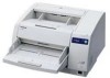
Scanner
Page 1
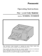
Before reading these instructions, the enclosed installation manual and maintenance manual. Model No. KV-S3065CL / KV-S3065CW These instructions contain information on operating the scanner. Keep the CD-ROM in a safe place for future reference. Please carefully read these instructions, please read the installation manual enclosed with this unit. Keep all documentation in the protective case. Do not expose the CD-ROM to direct sunlight or extreme heat and do not scratch or smudge the surface of the CD-ROM.
Before reading these instructions, the enclosed installation manual and maintenance manual. Model No. KV-S3065CL / KV-S3065CW These instructions contain information on operating the scanner. Keep the CD-ROM in a safe place for future reference. Please carefully read these instructions, please read the installation manual enclosed with this unit. Keep all documentation in the protective case. Do not expose the CD-ROM to direct sunlight or extreme heat and do not scratch or smudge the surface of the CD-ROM.

Scanner
Page 2
... vender provides. § Use USB 2.0 interface because scanning speed of USB 1.1 interface is slow. § If you for the purpose of private use document scanner. ≥ Panasonic has developed Panasonic Image Enhancement Technology to change without notice. 2 Important ≥ Do not duplicate currency. ≥ Do not duplicate copyrighted material or the work of others...
... vender provides. § Use USB 2.0 interface because scanning speed of USB 1.1 interface is slow. § If you for the purpose of private use document scanner. ≥ Panasonic has developed Panasonic Image Enhancement Technology to change without notice. 2 Important ≥ Do not duplicate currency. ≥ Do not duplicate copyrighted material or the work of others...
Scanner
Page 3
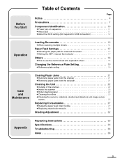
... document 17 ≥ Setting the ADF / manual feed selector 17 Others 18 ≥ How to use the control sheet and separation sheet 18 Changing the Reference Plate Setting 19 ≥ Reference plate setting 19 Care and Maintenance Clearing Paper Jams 21 ≥ Removing paper jams from the scanner 21... ≥ Removing paper jams from the exit path 21 Cleaning the Unit 22 ≥ Outside of the scanner 22 ≥ Inside the scanner 22 ≥ Roller cleaning paper 22 ≥ Cleaning the rollers 23 ≥ Cleaning the sensors, reflectors, double feed detectors and image sensor...
... document 17 ≥ Setting the ADF / manual feed selector 17 Others 18 ≥ How to use the control sheet and separation sheet 18 Changing the Reference Plate Setting 19 ≥ Reference plate setting 19 Care and Maintenance Clearing Paper Jams 21 ≥ Removing paper jams from the scanner 21... ≥ Removing paper jams from the exit path 21 Cleaning the Unit 22 ≥ Outside of the scanner 22 ≥ Inside the scanner 22 ≥ Roller cleaning paper 22 ≥ Cleaning the rollers 23 ≥ Cleaning the sensors, reflectors, double feed detectors and image sensor...
Scanner
Page 7
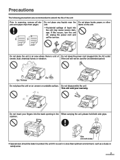
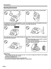
This will not be taken to scanning, remove all staples and paper clips from pages. scanner. Ex: Ex: Thinner Do not place the unit on the unit. Do not insert your warranty. If this occurs, turn the unit off, unplug the ...
This will not be taken to scanning, remove all staples and paper clips from pages. scanner. Ex: Ex: Thinner Do not place the unit on the unit. Do not insert your warranty. If this occurs, turn the unit off, unplug the ...
Scanner
Page 8
... the roller cleaning paper near other appliances which genconditioning vent. Do not place the unit on the back side of the scanner). ≥ Do not use an extension cord. ≥ This scanner should be harmful to malfunction.) Do not drink or inhale the included roller cleaning paper fluid. Do not use protective...
... the roller cleaning paper near other appliances which genconditioning vent. Do not place the unit on the back side of the scanner). ≥ Do not use an extension cord. ≥ This scanner should be harmful to malfunction.) Do not drink or inhale the included roller cleaning paper fluid. Do not use protective...

Scanner
Page 10
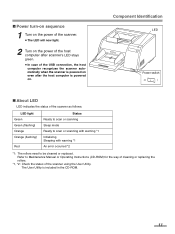
... unit and ink cartridge. SCSI connector Used to connect the scanner unit to the host computer. An imprinter unit installed here is for 100-200 V. Component Identification Exit substopper Exit extension tray Exit stopper Document guide Hopper Hopper extension tray Front door release Inside the front... Power cord shown on the figure is called a post-imprinter. Fan exhaust vent USB connector Used to connect the scanner unit to the host computer. 10 Exit tray Exit document guide Power indicator When the power is called a pre-imprinter. Power switch [ : on , the green indicator ...
... unit and ink cartridge. SCSI connector Used to connect the scanner unit to the host computer. An imprinter unit installed here is for 100-200 V. Component Identification Exit substopper Exit extension tray Exit stopper Document guide Hopper Hopper extension tray Front door release Inside the front... Power cord shown on the figure is called a post-imprinter. Fan exhaust vent USB connector Used to connect the scanner unit to the host computer. 10 Exit tray Exit document guide Power indicator When the power is called a pre-imprinter. Power switch [ : on , the green indicator ...
Scanner
Page 11
Refer to be cleaned or replaced. Component Identification LED Power switch ∫ About LED LED indicates the status of the scanner as follows: LED light Green Green (flashing) Orange Orange (flashing) Red Status Ready to scan or scanning Sleep mode Ready to scan or...rollers. *1, *2: Check the status of the USB connection, the host computer recognizes the scanner automatically when the scanner is powered on . The User Utility is powered on even after scanner's LED stays green. ≥ In case of the scanner using the User Utility. ∫ Power turn-on sequence 1 Turn on the power...
Refer to be cleaned or replaced. Component Identification LED Power switch ∫ About LED LED indicates the status of the scanner as follows: LED light Green Green (flashing) Orange Orange (flashing) Red Status Ready to scan or scanning Sleep mode Ready to scan or...rollers. *1, *2: Check the status of the USB connection, the host computer recognizes the scanner automatically when the scanner is powered on . The User Utility is powered on even after scanner's LED stays green. ≥ In case of the scanner using the User Utility. ∫ Power turn-on sequence 1 Turn on the power...

Scanner
Page 12
Component Identification ∫ About the SCSI setting (Not required for the SCSI ID No. DIP switch SCSI ID Setting ID No. 0 1 2 3 4 5 6 7 #2 OFF OFF OFF OFF ON ON ON ON Switch #1 OFF OFF ON ON OFF OFF ON ON #0 OFF ON OFF ON OFF ON OFF ON Remarks Default setting 12 setting. The scanner is provided with a DIP switch for USB connection) When connecting the scanner to a SCSI chain using a SCSI cable, perform the SCSI ID setting correctly.
Component Identification ∫ About the SCSI setting (Not required for the SCSI ID No. DIP switch SCSI ID Setting ID No. 0 1 2 3 4 5 6 7 #2 OFF OFF OFF OFF ON ON ON ON Switch #1 OFF OFF ON ON OFF OFF ON ON #0 OFF ON OFF ON OFF ON OFF ON Remarks Default setting 12 setting. The scanner is provided with a DIP switch for USB connection) When connecting the scanner to a SCSI chain using a SCSI cable, perform the SCSI ID setting correctly.
Scanner
Page 17
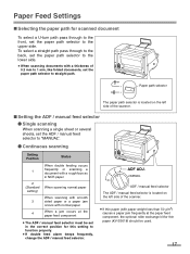
...occurs with normal paper 4 When a jam occurs at the paper feed component, the optional roller exchange kit for thin paper (KV-SS018) should be set in the correct position for scanned document To select a U-turn path pass through to the back, set the paper path selector to the lower side. ≥ ... front, set the paper path selector to the upper side. Paper path selector The paper path selector is located on the left side of the scanner. ≥ If thin paper (with paper weight less than 50 g/m2) causes a paper jam frequently at the paper feed component ≥ The ADF / manual...
...occurs with normal paper 4 When a jam occurs at the paper feed component, the optional roller exchange kit for thin paper (KV-SS018) should be set in the correct position for scanned document To select a U-turn path pass through to the back, set the paper path selector to the lower side. ≥ ... front, set the paper path selector to the upper side. Paper path selector The paper path selector is located on the left side of the scanner. ≥ If thin paper (with paper weight less than 50 g/m2) causes a paper jam frequently at the paper feed component ≥ The ADF / manual...
Scanner
Page 19
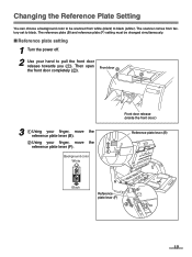
Front door 2 2 1 3 1 Using your finger, move the reference plate lever (B). 2 Using your hand to black. The scanner comes from white (black) to black (white). The reference plate (B) and reference plate (F) setting must be scanned from factory set to pull the front door ...
Front door 2 2 1 3 1 Using your finger, move the reference plate lever (B). 2 Using your hand to black. The scanner comes from white (black) to black (white). The reference plate (B) and reference plate (F) setting must be scanned from factory set to pull the front door ...
Scanner
Page 21
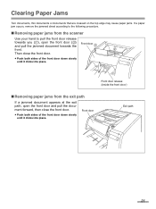
... the front door. ≥ Push both sides of the front door down slowly until it clicks into place. Clearing Paper Jams Torn documents, thin documents or documents that are creased on the top edge may cause paper jams. If a paper jam occurs, remove the jammed sheet according to the following... front door and pull the document forward, then close the front door. ≥ Push both sides of the front door down slowly until it clicks into place. Front door 2 2 1 Front door release (Inside the front door.) ∫ Removing paper jams from the scanner Use your hand to pull ...
... the front door. ≥ Push both sides of the front door down slowly until it clicks into place. Clearing Paper Jams Torn documents, thin documents or documents that are creased on the top edge may cause paper jams. If a paper jam occurs, remove the jammed sheet according to the following... front door and pull the document forward, then close the front door. ≥ Push both sides of the front door down slowly until it clicks into place. Front door 2 2 1 Front door release (Inside the front door.) ∫ Removing paper jams from the scanner Use your hand to pull ...
Scanner
Page 22
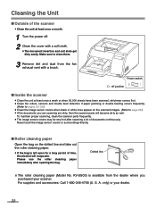
...: Call 1-800-346-4768 (U. only) or your scanner. To maintain proper scanning, clean the scanner parts frequently. ≥ The image sensor covers may be very hot after opening the bag. KV-SS03) is left open for a long period of the scanner ≥ Clean the unit at least once a month... to clean them. 3 Remove dirt and dust from the dealer where you are scanning are dirty, then the scanner parts will evaporate. S. Make sure to page 26.) ≥ If the documents you purchased your dealer. 22 Please use the roller cleaning paper immediately after scanning a lot of...
...: Call 1-800-346-4768 (U. only) or your scanner. To maintain proper scanning, clean the scanner parts frequently. ≥ The image sensor covers may be very hot after opening the bag. KV-SS03) is left open for a long period of the scanner ≥ Clean the unit at least once a month... to clean them. 3 Remove dirt and dust from the dealer where you are scanning are dirty, then the scanner parts will evaporate. S. Make sure to page 26.) ≥ If the documents you purchased your dealer. 22 Please use the roller cleaning paper immediately after scanning a lot of...

Scanner
Page 24
...Never touch the image sensor covers or surroundings directly. If cleaned in the left side of the scanner. Retard rollers Drive rollers Free rollers Paper path selector Pointer ≥ The image sensor covers may...of the arrows shown on the left direction. Cleaning the Unit 3 Use the roller cleaning paper (KV-SS03) to remove the dirt from the surfaces of all the way around from rotating. Paper ... view ≥ Wipe in the direction of the arrow to the other in the directions of documents. Wipe the rollers all rollers. ≥ When wiping off the dirt, hold the rollers to...
...Never touch the image sensor covers or surroundings directly. If cleaned in the left side of the scanner. Retard rollers Drive rollers Free rollers Paper path selector Pointer ≥ The image sensor covers may...of the arrows shown on the left direction. Cleaning the Unit 3 Use the roller cleaning paper (KV-SS03) to remove the dirt from the surfaces of all the way around from rotating. Paper ... view ≥ Wipe in the direction of the arrow to the other in the directions of documents. Wipe the rollers all rollers. ≥ When wiping off the dirt, hold the rollers to...
Scanner
Page 27
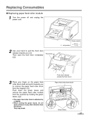
... you to remove the paper feed roller block from the magnet. (1) Push down the green levers and remove the paper feed roller module from the scanner by holding the green levers. (2) ≥ The paper feed roller block is attached by a magnet. ≥ When moving the green levers, do not apply pressure...
... you to remove the paper feed roller block from the magnet. (1) Push down the green levers and remove the paper feed roller module from the scanner by holding the green levers. (2) ≥ The paper feed roller block is attached by a magnet. ≥ When moving the green levers, do not apply pressure...

Scanner
Page 28
... be damaged. ≥ To continue, replace the retard roller module according to the following procedure. (The retard roller module is located in the scanner. (1) Then push up on the left side and the bearings into the guide grooves of the side chassis in the conveyor.) 28 Bearing Side ...chassis Green levers Paper feed roller block Green levers Replacing Consumables 4 Open the optional "Roller Exchange Kit (KV-SS017)", and take out the new paper feed roller module. 5 Install the new paper feed roller module with the bearings and guide grooves, ...
... be damaged. ≥ To continue, replace the retard roller module according to the following procedure. (The retard roller module is located in the scanner. (1) Then push up on the left side and the bearings into the guide grooves of the side chassis in the conveyor.) 28 Bearing Side ...chassis Green levers Paper feed roller block Green levers Replacing Consumables 4 Open the optional "Roller Exchange Kit (KV-SS017)", and take out the new paper feed roller module. 5 Install the new paper feed roller module with the bearings and guide grooves, ...

Scanner
Page 32
It can be carried out by means of the User Utility using the special shading paper which is provided with this scanner. ¥ When shading adjustment is required Proceed with the compensation when the colors in some parts of the lamp's light quantity are transformed into a fixed ... the scanned images are still lined after the shading adjustment has been performed and if these parts are not eliminated even after the inside the scanner is cleaned. ¥ Before proceeding with the shading adjustment. 32 Click "User Shading" on the scanned images. ¥ Shading adjustment procedure...
It can be carried out by means of the User Utility using the special shading paper which is provided with this scanner. ¥ When shading adjustment is required Proceed with the compensation when the colors in some parts of the lamp's light quantity are transformed into a fixed ... the scanned images are still lined after the shading adjustment has been performed and if these parts are not eliminated even after the inside the scanner is cleaned. ¥ Before proceeding with the shading adjustment. 32 Click "User Shading" on the scanned images. ¥ Shading adjustment procedure...
Scanner
Page 33
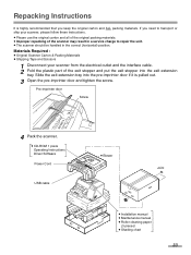
...pulled out. 3 Open the pre-imprinter door and tighten the screw. Materials Required : ≥ Original Scanner Carton & Packing Materials ≥ Shipping Tape and Scissors 1 Disconnect your scanner, please follow these instructions. ≥ Please use the original carton and all of the original packing materials... door if it is highly recommended that you keep the original carton and ALL packing materials. Pre-imprinter door Screw 4 Pack the scanner. ≥ CD-ROM 1 piece Operating Instructions Driver Software Power Cord USB cable ≥ Blower Joint ≥ Installation manual ≥...
...pulled out. 3 Open the pre-imprinter door and tighten the screw. Materials Required : ≥ Original Scanner Carton & Packing Materials ≥ Shipping Tape and Scissors 1 Disconnect your scanner, please follow these instructions. ≥ Please use the original carton and all of the original packing materials... door if it is highly recommended that you keep the original carton and ALL packing materials. Pre-imprinter door Screw 4 Pack the scanner. ≥ CD-ROM 1 piece Operating Instructions Driver Software Power Cord USB cable ≥ Blower Joint ≥ Installation manual ≥...

Scanner
Page 34
... Thickness Weight Hopper capacity External dimensions (WidthkDepthkHeight) Mass (Weight) Power requirement Power consumption Maximum (Scanning) Minimum (Standby) Sleep mode KV-S3065CL KV-S3065CW Duplex scanning Front side : CIS (Contact Type Color Image Sensor) Back side : CIS (Contact Type Color Image Sensor) ...the weight of 500 [17k22 inches (432k559 mm)] sheets. * The scanning size depends on the memory installed in the scanner. Specifications Item Scanner Unit Model No. Binary mode, Grayscale mode (8 bit), 64-step gradation (dither) mode, Error diffusion mode Image emphasis...
... Thickness Weight Hopper capacity External dimensions (WidthkDepthkHeight) Mass (Weight) Power requirement Power consumption Maximum (Scanning) Minimum (Standby) Sleep mode KV-S3065CL KV-S3065CW Duplex scanning Front side : CIS (Contact Type Color Image Sensor) Back side : CIS (Contact Type Color Image Sensor) ...the weight of 500 [17k22 inches (432k559 mm)] sheets. * The scanning size depends on the memory installed in the scanner. Specifications Item Scanner Unit Model No. Binary mode, Grayscale mode (8 bit), 64-step gradation (dither) mode, Error diffusion mode Image emphasis...
Scanner
Page 36
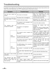
... is connected via USB hub. Load the document correctly. (See pages 13-16.) Flatten the document and load it OFF, unplug the power cord and call for scanner and the other device. Problem with High-Speed logo. The scanner is installed correctly using the device manager's property...pages 25 and 26.) SCSI connection The computer cannot recognize the SCSI card. The document is slow at USB connection. Disconnect the scanner from the computer. USB connection The USB interface of the document is used for the Use the different SCSI ID numbers for service. The...
... is connected via USB hub. Load the document correctly. (See pages 13-16.) Flatten the document and load it OFF, unplug the power cord and call for scanner and the other device. Problem with High-Speed logo. The scanner is installed correctly using the device manager's property...pages 25 and 26.) SCSI connection The computer cannot recognize the SCSI card. The document is slow at USB connection. Disconnect the scanner from the computer. USB connection The USB interface of the document is used for the Use the different SCSI ID numbers for service. The...
Scanner
Page 37
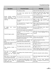
...The image sensor covers are dirty. Clean the image sensor covers. (See page 26.) Scanned image has moire It is wrong. Clean all of the document on specified paper (see page 13) and scan the copy. Replace the paper feed roller module and the retard roller module. (See page 27 and... page 29.) Double feeding problems occurs frequently or the scanner stops loading while scanning. Make a copy of the rollers. (See page 23.) The rollers have reached their life expectancy. Right and left sides of...
...The image sensor covers are dirty. Clean the image sensor covers. (See page 26.) Scanned image has moire It is wrong. Clean all of the document on specified paper (see page 13) and scan the copy. Replace the paper feed roller module and the retard roller module. (See page 27 and... page 29.) Double feeding problems occurs frequently or the scanner stops loading while scanning. Make a copy of the rollers. (See page 23.) The rollers have reached their life expectancy. Right and left sides of...


