Service Manual
Page 2
... electrical installation are a major cause of the power point, consult a qualified electrician. WARNING This apparatus must be connected to the terminal which is not in the U.K.) Disconnect the mains plug from your safety and convenience. A replacement fuse cover can be fitted please observe the wiring code as follows: The wire which is to replace the fuse Open the...
... electrical installation are a major cause of the power point, consult a qualified electrician. WARNING This apparatus must be connected to the terminal which is not in the U.K.) Disconnect the mains plug from your safety and convenience. A replacement fuse cover can be fitted please observe the wiring code as follows: The wire which is to replace the fuse Open the...
Service Manual
Page 5
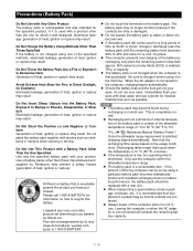
... Manual "Battery Power") Once the allowable range requirement is satisfied, charging begins automatically. NOTE The battery pack may result. tery capacity. Appendix Use of battery packs other than approx. 95% (when Economy Mode (ECO) is enabled: 75%) of capacity. The battery pack is not charged when the computer is completely normal. When the AC adaptor is connected to recycle this battery. Only use ) the battery...
... Manual "Battery Power") Once the allowable range requirement is satisfied, charging begins automatically. NOTE The battery pack may result. tery capacity. Appendix Use of battery packs other than approx. 95% (when Economy Mode (ECO) is enabled: 75%) of capacity. The battery pack is not charged when the computer is completely normal. When the AC adaptor is connected to recycle this battery. Only use ) the battery...
Service Manual
Page 7
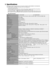
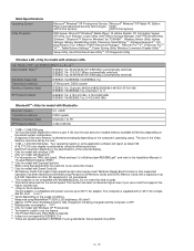
...Jack (Miniature jack, 3.5 DIA, Impedance 32 Њ, Output Power 4 mW × 2) Keyboard / Pointing Device Power Supply AC Adaptor*15 82 keys / Touch Pad / Touchscreen (Anti- 82 keys / Touch Pad / Digitizer (Anti-Reflec- To check CPU speed, memory size and the hard disk drive (HDD) size: Run the Setup Utility ( Reference Manual "Setup Utility") and select [Information] menu. [CPU Speed]: CPU speed, [System Memory]: Memory size, [Hard Disk]: Hard disk drive size Main Specifications Model No. Specifications This page provides the specifications for the basic model CF-19FHGAXBM/CF...
...Jack (Miniature jack, 3.5 DIA, Impedance 32 Њ, Output Power 4 mW × 2) Keyboard / Pointing Device Power Supply AC Adaptor*15 82 keys / Touch Pad / Touchscreen (Anti- 82 keys / Touch Pad / Digitizer (Anti-Reflec- To check CPU speed, memory size and the hard disk drive (HDD) size: Run the Setup Utility ( Reference Manual "Setup Utility") and select [Information] menu. [CPU Speed]: CPU speed, [System Memory]: Memory size, [Hard Disk]: Hard disk drive size Main Specifications Model No. Specifications This page provides the specifications for the basic model CF-19FHGAXBM/CF...
Service Manual
Page 8
...Icon Enlarger, Loupe Utility, Intel® Matrix Storage Manager, Intel® PROSet/Wireless Software*7, Bluetooth™ Stack for Windows® by TOSHIBA*8 , Wireless Switch Utility, Hotkey Settings, Battery Recalibration Utility, Panasonic Hand Writing*20, Software Keyboard*20, Display Rotation Tool, InÞneon TPM Professional Package*21, Recover ProTM 6*21 or Recover ProTM VX*21 , Tablet Buttons Settings*20, Power Saving Utility, Wireless Connection Disable Utility*21 Setup Utility, Hard Disk Data Erase Utility*22, PC-Diagnostic Utility Wireless LAN Intel Wireless WiFi Link 4965AG...
...Icon Enlarger, Loupe Utility, Intel® Matrix Storage Manager, Intel® PROSet/Wireless Software*7, Bluetooth™ Stack for Windows® by TOSHIBA*8 , Wireless Switch Utility, Hotkey Settings, Battery Recalibration Utility, Panasonic Hand Writing*20, Software Keyboard*20, Display Rotation Tool, InÞneon TPM Professional Package*21, Recover ProTM 6*21 or Recover ProTM VX*21 , Tablet Buttons Settings*20, Power Saving Utility, Wireless Connection Disable Utility*21 Setup Utility, Hard Disk Data Erase Utility*22, PC-Diagnostic Utility Wireless LAN Intel Wireless WiFi Link 4965AG...
Service Manual
Page 9
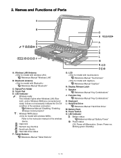
... This indicator lights when Wireless LAN, Bluetooth, and/or Wireless WAN are connected and ready. 2. Names and Functions of the wireless device. : Caps lock : Numeric key (NumLk) : Scroll lock (ScrLk) : Hard disk drive status F: Tablet Buttons Reference Manual "Tablet Buttons" G: LCD Reference Manual "Touchscreen" Reference Manual "Digitizer" H: Display Release Latch I: Speaker Reference Manual "Key Combinations" J: Function Key Reference Manual "Key Combinations" K: Keyboard L: Hard Disk Drive Reference Manual "Hard Disk Drive" M: Battery Pack N: Power Switch O: LED Indicator : Battery...
... This indicator lights when Wireless LAN, Bluetooth, and/or Wireless WAN are connected and ready. 2. Names and Functions of the wireless device. : Caps lock : Numeric key (NumLk) : Scroll lock (ScrLk) : Hard disk drive status F: Tablet Buttons Reference Manual "Tablet Buttons" G: LCD Reference Manual "Touchscreen" Reference Manual "Digitizer" H: Display Release Latch I: Speaker Reference Manual "Key Combinations" J: Function Key Reference Manual "Key Combinations" K: Keyboard L: Hard Disk Drive Reference Manual "Hard Disk Drive" M: Battery Pack N: Power Switch O: LED Indicator : Battery...
Service Manual
Page 10
... Manual "Modem" E: LAN Port Reference Manual "LAN" F: SD Memory Card Indicator (Blinking: During access) Reference Manual "SD Memory Card" G: SD Memory Card Slot Reference Manual "SD Memory Card" H: Wireless Switch Reference Manual "Disabling / Enabling Wireless Communication" I: PC Card Slot Reference Manual "PC Card / ExpressCard" Smart Card Slot Reference Manual "Smart Card" J: ExpressCard Slot Reference Manual "PC Card / ExpressCard" PC Card Slot Reference Manual "PC Card / ExpressCard" K: Headphone Jack You can be possible, or malfunctions may not be connected. When they are used...
... Manual "Modem" E: LAN Port Reference Manual "LAN" F: SD Memory Card Indicator (Blinking: During access) Reference Manual "SD Memory Card" G: SD Memory Card Slot Reference Manual "SD Memory Card" H: Wireless Switch Reference Manual "Disabling / Enabling Wireless Communication" I: PC Card Slot Reference Manual "PC Card / ExpressCard" Smart Card Slot Reference Manual "Smart Card" J: ExpressCard Slot Reference Manual "PC Card / ExpressCard" PC Card Slot Reference Manual "PC Card / ExpressCard" K: Headphone Jack You can be possible, or malfunctions may not be connected. When they are used...
Service Manual
Page 13
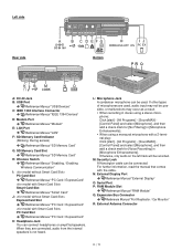
.... OK Return set should all keys cannot be turned ON , Set fails to display. Trouble symptoms on specific media, CD media can be turned ON , Set fails to light up utility starting Not displayed properly on screen. Since flaws may appear on some of delivery from factory . SETNADRT Troubleshooting Please take note of K/B connector in operation. Failure in operation. Replace if defective. Refer to troubleshooting: 1. Main board check NG Replace main board OK Make sure of...
.... OK Return set should all keys cannot be turned ON , Set fails to display. Trouble symptoms on specific media, CD media can be turned ON , Set fails to light up utility starting Not displayed properly on screen. Since flaws may appear on some of delivery from factory . SETNADRT Troubleshooting Please take note of K/B connector in operation. Failure in operation. Replace if defective. Refer to troubleshooting: 1. Main board check NG Replace main board OK Make sure of...
Service Manual
Page 15
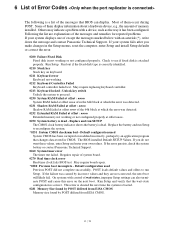
... you make changes in the Setup menus, reset the computer, enter Setup and install Setup defaults or correct the error. 0200 Failure Fixed Disk Fixed disk in CMOS. If the failure was detected. 0232 Extended RAM Failed at offset : nnnn Extended memory not working or not configured properly at offset nnnn of memory installed. The BIOS installed Default SETUP Values. Check to reconfigure the system. *0251 System CMOS checksum bad - Replace and run SETUP The CMOS clock battery indicator shows the battery...
... you make changes in the Setup menus, reset the computer, enter Setup and install Setup defaults or correct the error. 0200 Failure Fixed Disk Fixed disk in CMOS. If the failure was detected. 0232 Extended RAM Failed at offset : nnnn Extended memory not working or not configured properly at offset nnnn of memory installed. The BIOS installed Default SETUP Values. Check to reconfigure the system. *0251 System CMOS checksum bad - Replace and run SETUP The CMOS clock battery indicator shows the battery...
Service Manual
Page 16
... located on the screen. If it cannot locate the address, it displays ????. Enter Setup and see if fixed disk and drive A: are properly identified. 02D0 System cache error - A parity error indicates that some data has been corrupted. Troubleshooting BIOS attempts to locate the address and display it on the screen. Cache disabled Contact Panasonic Technical Support. 02F0: CPU ID: CPU socket number for specified device. device address Conflict Address conflict for Multi-Processor error. 02F4: EISA CMOS...
... located on the screen. If it cannot locate the address, it displays ????. Enter Setup and see if fixed disk and drive A: are properly identified. 02D0 System cache error - A parity error indicates that some data has been corrupted. Troubleshooting BIOS attempts to locate the address and display it on the screen. Cache disabled Contact Panasonic Technical Support. 02F0: CPU ID: CPU socket number for specified device. device address Conflict Address conflict for Multi-Processor error. 02F4: EISA CMOS...
Service Manual
Page 17
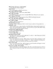
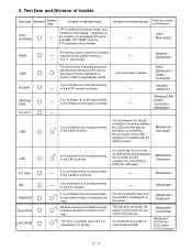
... "Panasonic" start "PC-Diagnostic utility" again after doing the power supply switch in DVD of the USB connection, even if DVD is normal, becomes an error if legacy USB is set to "Invalidity" by "Main" menu such as "Flat pad" is judged that case,restarts pushing"Alt" + "Ctrl" + "Del" key. Do not disclose this model, a standard test and the enhancing test by the module of " Is the default value...
... "Panasonic" start "PC-Diagnostic utility" again after doing the power supply switch in DVD of the USB connection, even if DVD is normal, becomes an error if legacy USB is set to "Invalidity" by "Main" menu such as "Flat pad" is judged that case,restarts pushing"Alt" + "Ctrl" + "Del" key. Do not disclose this model, a standard test and the enhancing test by the module of " Is the default value...
Service Manual
Page 18
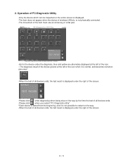
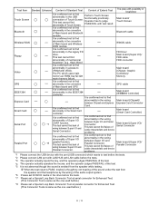
Operation of PC-Diagnostic Utility -Only the device which can be inspected on the way. -When the test of all devices ends, the test result is displayed under the diagnosis, blue and yellow are alternately displayed at the left of wireless LAN etc. 2. The diagnosis result of the device greens at... restart "PC-Diagnostic utility". *Each device is tested from the beginning, and it is not possible to restart on the entire screen is not physically connected. -The movement of the item must use an arrow key or a flat pad. -As for the device under the right of the screen. is displayed. -The...
Operation of PC-Diagnostic Utility -Only the device which can be inspected on the way. -When the test of all devices ends, the test result is displayed under the diagnosis, blue and yellow are alternately displayed at the left of wireless LAN etc. 2. The diagnosis result of the device greens at... restart "PC-Diagnostic utility". *Each device is tested from the beginning, and it is not possible to restart on the entire screen is not physically connected. -The movement of the item must use an arrow key or a flat pad. -As for the device under the right of the screen. is displayed. -The...
Service Manual
Page 19
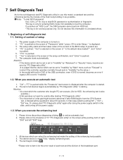
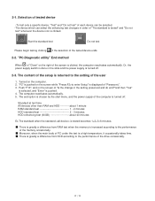
... enter Setup" is displayed of the screen is pushed. 4. The computer reactivates automatically. 5. Push "F10", and on the right of "Panasonic". 3. Or, the power supply switch is done in the slide and the power supply is greatly a difference from HDD according to the setting of the tested device ends. 2-2. "PC-Diagnostic utility" End method When of "Close" on the screen of "Is the change in order...
... enter Setup" is displayed of the screen is pushed. 4. The computer reactivates automatically. 5. Push "F10", and on the right of "Panasonic". 3. Or, the power supply switch is done in the slide and the power supply is greatly a difference from HDD according to the setting of the tested device ends. 2-2. "PC-Diagnostic utility" End method When of "Close" on the screen of "Is the change in order...
Service Manual
Page 20
... the LAN controller. The operation is actually displayed on the screen. It is displayed on the screen by confirming the connection of the USB equipment connected with possibility of breakdown CPU / Main board RAM HDD MODEM Wireless LAN Sound *5 USB All memory space is tested in about two minutes regardless of points of enhancing test Place with the USB connector. Mainboard Mainboard / Keyboard Mainboard / Touch Pad Mainboard / DVD Drive / DVD Cable / DVD Connector The record area frequently accessed with LAN cable...
... the LAN controller. The operation is actually displayed on the screen. It is displayed on the screen by confirming the connection of the USB equipment connected with possibility of breakdown CPU / Main board RAM HDD MODEM Wireless LAN Sound *5 USB All memory space is tested in about two minutes regardless of points of enhancing test Place with the USB connector. Mainboard Mainboard / Keyboard Mainboard / Touch Pad Mainboard / DVD Drive / DVD Cable / DVD Connector The record area frequently accessed with LAN cable...
Service Manual
Page 21
... wiring of the audio output system. *6 Please set DVD/CD media in the wiring between Super I /O and Parallel Connector. It is confirmed not to find abnormality in access to VRAM with VESA. This test cannot find failure of cable characteristic and device problems. The place with LAN cable before .) Test Item Touch Screen Bluetooth Wireless WAN Floppy Video GPS IEEE1394 Express Card Smart Card Serial Port Parallel Port Standard Enhanced...
... wiring of the audio output system. *6 Please set DVD/CD media in the wiring between Super I /O and Parallel Connector. It is confirmed not to find abnormality in access to VRAM with VESA. This test cannot find failure of cable characteristic and device problems. The place with LAN cable before .) Test Item Touch Screen Bluetooth Wireless WAN Floppy Video GPS IEEE1394 Express Card Smart Card Serial Port Parallel Port Standard Enhanced...
Service Manual
Page 22
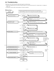
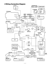
... CN901 CN900 LCD Touch Screen Panel JK601 JK600 CN604 CN600 SERIAL EXTERNAL PORT DISPLAY PORT CN881 CN882 CN880 RTC BATTERY CN883 JK880 DC-IN I/O PCB I/F PCB CN851 H/P MIC CN16 CN9 CN14 CN901 AUDIO PCB KEYBOARD CN27 CN18 CN25 CN17 CN8 CN5 CN11 CN3 COIN BATTERY MAIN PCB CN21 CN6 CN24 CN22 USB IEEE 1394 MODEM PCB CN12 SD PCB LAN PORT CN882 HDD PCMCIA UNIT POWER SW PCB...
... CN901 CN900 LCD Touch Screen Panel JK601 JK600 CN604 CN600 SERIAL EXTERNAL PORT DISPLAY PORT CN881 CN882 CN880 RTC BATTERY CN883 JK880 DC-IN I/O PCB I/F PCB CN851 H/P MIC CN16 CN9 CN14 CN901 AUDIO PCB KEYBOARD CN27 CN18 CN25 CN17 CN8 CN5 CN11 CN3 COIN BATTERY MAIN PCB CN21 CN6 CN24 CN22 USB IEEE 1394 MODEM PCB CN12 SD PCB LAN PORT CN882 HDD PCMCIA UNIT POWER SW PCB...
Service Manual
Page 23
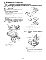
... fixed with two-sided tape. Carefully remove the Palm Top Cover Sheet not to the Suspend or hibernation mode. 9 Disassembly/Reassembly Note: Power off the power. ï Disconnect the AC adaptor. ï Remove the optional DIMM memory card and PCMCIA card if they are connected. ï Remove other devices if they are connected. Do not shut down Windows and turn off the computer. Disassembly Instructions 9.1.1. Preparation Before disassembling, be recycled. HDD Case B HDD...
... fixed with two-sided tape. Carefully remove the Palm Top Cover Sheet not to the Suspend or hibernation mode. 9 Disassembly/Reassembly Note: Power off the power. ï Disconnect the AC adaptor. ï Remove the optional DIMM memory card and PCMCIA card if they are connected. ï Remove other devices if they are connected. Do not shut down Windows and turn off the computer. Disassembly Instructions 9.1.1. Preparation Before disassembling, be recycled. HDD Case B HDD...
Service Manual
Page 26
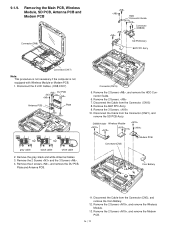
Disconnect the 2 LCD Cables. (CN8,CN17) DU PCB Antenna PCB Plate gray cable black cable white cable 2. Remove the 2 Screws. 7. Remove the 3 Screws. 10. Disconnect the Cable from the Connector. (CN15) 8. Remove the 2 Screws and the 3 Screws . 4. Remove the 2 Screws , and remove the HDD Connector Guide. 6. Disconnect the Cable from the Connector (CN3), and remove the Coin Battery. 12. Remove the BAT FPC Ass'y. 9. DIMM Holder Wireless Module Connector(CN3) Modem...
Disconnect the 2 LCD Cables. (CN8,CN17) DU PCB Antenna PCB Plate gray cable black cable white cable 2. Remove the 2 Screws. 7. Remove the 3 Screws. 10. Disconnect the Cable from the Connector. (CN15) 8. Remove the 2 Screws and the 3 Screws . 4. Remove the 2 Screws , and remove the HDD Connector Guide. 6. Disconnect the Cable from the Connector (CN3), and remove the Coin Battery. 12. Remove the BAT FPC Ass'y. 9. DIMM Holder Wireless Module Connector(CN3) Modem...
Service Manual
Page 31
... the frame. (0 to 3.0 Kgf) B Order of fixing 33 35mm Detail of the Frame within 0 to the LCD Frame. Attention when CF-19 series is repaired ï Please execute writing BIOS ID when you exchange the Main Board. ï Parts (Sheet and rubber) etc. related various the Conductive Cloth and Heat Spreader cannot be recycled. Set the LCD UNIT to 0.5 mm) Screw 2 Screw...
... the frame. (0 to 3.0 Kgf) B Order of fixing 33 35mm Detail of the Frame within 0 to the LCD Frame. Attention when CF-19 series is repaired ï Please execute writing BIOS ID when you exchange the Main Board. ï Parts (Sheet and rubber) etc. related various the Conductive Cloth and Heat Spreader cannot be recycled. Set the LCD UNIT to 0.5 mm) Screw 2 Screw...
Service Manual
Page 33
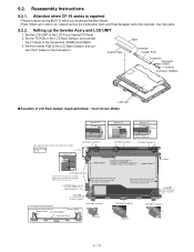
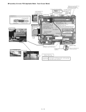
... 1 Connect the Cable to the Cabinet.) LCD Side Cushion E Insulation Parts Insulation Parts Avoid any stress on the CCFL Cable. LCD Cable TS middle of right and left sides on the Back Dumper as shown below and overlap on the Cable when connecting the CCFL Cable. ■ Assembly of Inverter PCB (Applicable Model : Touch Screen Model) Inverter Ass'y Confirm the direction of the Inverter board when...
... 1 Connect the Cable to the Cabinet.) LCD Side Cushion E Insulation Parts Insulation Parts Avoid any stress on the CCFL Cable. LCD Cable TS middle of right and left sides on the Back Dumper as shown below and overlap on the Cable when connecting the CCFL Cable. ■ Assembly of Inverter PCB (Applicable Model : Touch Screen Model) Inverter Ass'y Confirm the direction of the Inverter board when...
Service Manual
Page 74
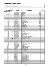
... PCB, MAIN PCB, AUDIO PCB, IO PCB, PAD PCB, SW PCB, LED-LEFT PCB, PR PCB, LED-RIGHT PCB, SD PCB, HSDPA PCB, POWERSW PCB, EXT ANT UNIT PCB, BT BAT FPC UNIT WWAN MAIN ANT WWAN AUX ANT LAN-MAIN BT ANT LAN AUX ANT CF-19 TS PCB UNIT WWAN COAXIAL CABLE LCD CABLE TS INVERTER HARD DISK KEYBOARD VISTA, U.S. NO and OS...
... PCB, MAIN PCB, AUDIO PCB, IO PCB, PAD PCB, SW PCB, LED-LEFT PCB, PR PCB, LED-RIGHT PCB, SD PCB, HSDPA PCB, POWERSW PCB, EXT ANT UNIT PCB, BT BAT FPC UNIT WWAN MAIN ANT WWAN AUX ANT LAN-MAIN BT ANT LAN AUX ANT CF-19 TS PCB UNIT WWAN COAXIAL CABLE LCD CABLE TS INVERTER HARD DISK KEYBOARD VISTA, U.S. NO and OS...


