Installation Guide
Page 1
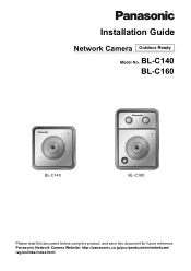
Panasonic Network Camera Website: http://panasonic.co.jp/pcc/products/en/netwkcam/ regionlinks/index.html BL-C140 BL-C160 BL-C140 BL-C160 Please read this document before using the product, and save this document for future reference. Installation Guide Network Camera Outdoor Ready Model No.
Panasonic Network Camera Website: http://panasonic.co.jp/pcc/products/en/netwkcam/ regionlinks/index.html BL-C140 BL-C160 BL-C140 BL-C160 Please read this document before using the product, and save this document for future reference. Installation Guide Network Camera Outdoor Ready Model No.
Installation Guide
Page 6
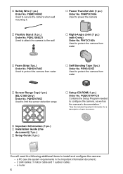
...PQKL10082Z1 Used to attach the camera to install and configure the camera. - PSHG1235Z Used to protect the camera from water … Sensor Range Cap (1 pc.) [BL-C160 Only] Order No. PQQX15704TCD Contains the Setup Program needed to configure the camera, as well as the camera's documentation.* *See the ...the Important Information document) - 2 LAN cables (1 indoor cable and 1 outdoor cable) - PQME10080Z Used to limit the sensor detection range … Setup CD-ROM (1 pc.) Order No. PQHG10765Z Used to secure the camera when wall mounting it. … Power Transfer Unit (1 pc.) Order No...
...PQKL10082Z1 Used to attach the camera to install and configure the camera. - PSHG1235Z Used to protect the camera from water … Sensor Range Cap (1 pc.) [BL-C160 Only] Order No. PQQX15704TCD Contains the Setup Program needed to configure the camera, as well as the camera's documentation.* *See the ...the Important Information document) - 2 LAN cables (1 indoor cable and 1 outdoor cable) - PQME10080Z Used to limit the sensor detection range … Setup CD-ROM (1 pc.) Order No. PQHG10765Z Used to secure the camera when wall mounting it. … Power Transfer Unit (1 pc.) Order No...
Installation Guide
Page 17
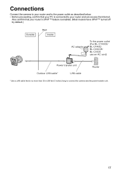
... your router and to the power outlet as described below. • Before proceeding, confirm that your PC is connected to connect the camera and the power transfer unit. 17 Also confirm that is no more than 30 m (98 feet 5 inches) long to your router's UPnP™ feature ...is enabled. (Most routers have UPnP™ turned off by default.) Outside Wall Inside AC adaptor To the power outlet (For BL-C140CE/ BL-C140E/ BL-C160CE/ BL-C160E use an AC cord) Power transfer unit Outdoor LAN cable* LAN cable Router * Use a LAN cable that your router and can access the Internet.
... your router and to the power outlet as described below. • Before proceeding, confirm that your PC is connected to connect the camera and the power transfer unit. 17 Also confirm that is no more than 30 m (98 feet 5 inches) long to your router's UPnP™ feature ...is enabled. (Most routers have UPnP™ turned off by default.) Outside Wall Inside AC adaptor To the power outlet (For BL-C140CE/ BL-C140E/ BL-C160CE/ BL-C160E use an AC cord) Power transfer unit Outdoor LAN cable* LAN cable Router * Use a LAN cable that your router and can access the Internet.
Installation Guide
Page 18
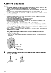
... outdoor LAN cable through the ground, do not connect cables under the ground. Install cables through a conduit to protect them from water. • Refer to page 9-12 for use with wooden walls only. • Prolonged exposure to direct sunlight or halogen light may damage the camera's... image sensor. Drive the screws into a soft material. Mount the camera appropriately. • Make sure to prevent the camera from falling. Camera Mounting Caution • Do not drive the screws into a secure...
... outdoor LAN cable through the ground, do not connect cables under the ground. Install cables through a conduit to protect them from water. • Refer to page 9-12 for use with wooden walls only. • Prolonged exposure to direct sunlight or halogen light may damage the camera's... image sensor. Drive the screws into a soft material. Mount the camera appropriately. • Make sure to prevent the camera from falling. Camera Mounting Caution • Do not drive the screws into a secure...
Installation Guide
Page 21
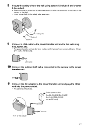
To the power outlet (For BL-C140CE/BL-C140E/ BL-C160CE/BL-C160E use an anchor to help secure the camera to the wall. • Leave some slack in place with 2 pieces from screw A (4 mm x 20 mm [3/16 inch x 13/16 inch]). 8 Secure the safety wire ... transfer unit and to the power transfer unit and plug the other end into the power outlet. • The camera will activate. LAN Cable 10 Connect the outdoor LAN cable connected to the camera to the power transfer unit. 11 Connect the AC adaptor to the switching hub, router, etc. • The power...
To the power outlet (For BL-C140CE/BL-C140E/ BL-C160CE/BL-C160E use an anchor to help secure the camera to the wall. • Leave some slack in place with 2 pieces from screw A (4 mm x 20 mm [3/16 inch x 13/16 inch]). 8 Secure the safety wire ... transfer unit and to the power transfer unit and plug the other end into the power outlet. • The camera will activate. LAN Cable 10 Connect the outdoor LAN cable connected to the camera to the power transfer unit. 11 Connect the AC adaptor to the switching hub, router, etc. • The power...
