
Installation Guide
Page 7
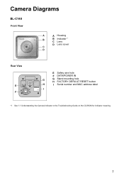
Camera Diagrams BL-C140 Front View A A Housing B B Indicator*1 C Lens D Lens cover C D Rear View E F E Safety wire hole F DATA/POWER IN G G Stand mounting hole H FACTORY DEFAULT RESET button H I Serial number and MAC address label I *1 See 1.1 Understanding the Camera Indicator in the Troubleshooting Guide on the CD-ROM for indicator meaning. 7
Camera Diagrams BL-C140 Front View A A Housing B B Indicator*1 C Lens D Lens cover C D Rear View E F E Safety wire hole F DATA/POWER IN G G Stand mounting hole H FACTORY DEFAULT RESET button H I Serial number and MAC address label I *1 See 1.1 Understanding the Camera Indicator in the Troubleshooting Guide on the CD-ROM for indicator meaning. 7
Installation Guide
Page 8
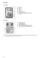
BL-C160 Front View A Housing A B Light C Indicator*1 B D Lens E Lens cover C F Brightness sensor*2 G Built-in sensor (pyroelectric infrared D sensor) E F G Rear View H I H Safety wire hole I DATA/POWER IN J Stand mounting hole K FACTORY DEFAULT RESET button L Serial number and MAC address label J K L *1 See 1.1 Understanding the Camera Indicator in the Troubleshooting Guide on the CD-ROM for indicator meaning. *2 The brightness sensor determines when the light turns on. 8
BL-C160 Front View A Housing A B Light C Indicator*1 B D Lens E Lens cover C F Brightness sensor*2 G Built-in sensor (pyroelectric infrared D sensor) E F G Rear View H I H Safety wire hole I DATA/POWER IN J Stand mounting hole K FACTORY DEFAULT RESET button L Serial number and MAC address label J K L *1 See 1.1 Understanding the Camera Indicator in the Troubleshooting Guide on the CD-ROM for indicator meaning. *2 The brightness sensor determines when the light turns on. 8
