Installation Guide
Page 2
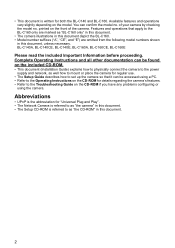
... the camera's features. • Refer to the BL-C160 only are marked as "the CD-ROM" in this document, unless necessary. You can be found on the model. BL-C140A, BL-C140CE, BL-C140E, BL-C160A, BL-C160CE, BL-C160E ...Please read the included Important Information before proceeding. Available features and operations vary slightly depending on the included CD-ROM. • This document (Installation Guide) explains how to physically connect the camera to the power supply and network, as well how to mount or place the camera...
... the camera's features. • Refer to the BL-C160 only are marked as "the CD-ROM" in this document, unless necessary. You can be found on the model. BL-C140A, BL-C140CE, BL-C140E, BL-C160A, BL-C160CE, BL-C160E ...Please read the included Important Information before proceeding. Available features and operations vary slightly depending on the included CD-ROM. • This document (Installation Guide) explains how to physically connect the camera to the power supply and network, as well how to mount or place the camera...
Installation Guide
Page 3
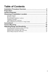
Table of Contents Installation Procedure Overview 4 Preparation 5 Camera Diagrams 7 Choosing an Installation Location 9 Detection Features...9 Mounting Location...13 Recommended Installation Locations 14 Installation Examples ...15 Light Brightness (BL-C160 Only 16 Effect of Brightness and Distance on Image Quality 16 Connections 17 Camera Mounting 18 Adjusting Range and Sensitivity 23 Preventing Sensor Interference (BL-C160 Only 23 Adjusting Motion Detection Sensitivity 25 Adjusting Sensor Sensitivity (BL-C160 Only 26 Sensor Range Caps (BL-C160 Only 27 3
Table of Contents Installation Procedure Overview 4 Preparation 5 Camera Diagrams 7 Choosing an Installation Location 9 Detection Features...9 Mounting Location...13 Recommended Installation Locations 14 Installation Examples ...15 Light Brightness (BL-C160 Only 16 Effect of Brightness and Distance on Image Quality 16 Connections 17 Camera Mounting 18 Adjusting Range and Sensitivity 23 Preventing Sensor Interference (BL-C160 Only 23 Adjusting Motion Detection Sensitivity 25 Adjusting Sensor Sensitivity (BL-C160 Only 26 Sensor Range Caps (BL-C160 Only 27 3
Installation Guide
Page 4
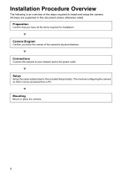
... Confirm you have all the items required for installation. Mounting Mount or place the camera. 4 All steps are explained in the included Setup Guide). Setup Setup the camera (described in this document unless otherwise noted. Connections Connect the camera to your network and to install and setup the camera. Installation Procedure Overview The following is an overview...
... Confirm you have all the items required for installation. Mounting Mount or place the camera. 4 All steps are explained in the included Setup Guide). Setup Setup the camera (described in this document unless otherwise noted. Connections Connect the camera to your network and to install and setup the camera. Installation Procedure Overview The following is an overview...
Installation Guide
Page 5
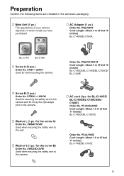
... 10 inches) BL-C140A/BL-C160A BL-C140 BL-C160 … Screw A (6 pcs.) Order No. XTB26 + 10GVW Used for securing the safety wire to the camera. … Washer L (1 pc. PFJA02A006Z Cord Length: About 1.8 m (5 feet 11 inches) BL-C140CE/BL-C160CE Order No. Order No. for fixing the right-angle joint to the camera and for BL-C140CE/ BL-C140E/BL-C160CE/BLC160E...
... 10 inches) BL-C140A/BL-C160A BL-C140 BL-C160 … Screw A (6 pcs.) Order No. XTB26 + 10GVW Used for securing the safety wire to the camera. … Washer L (1 pc. PFJA02A006Z Cord Length: About 1.8 m (5 feet 11 inches) BL-C140CE/BL-C160CE Order No. Order No. for fixing the right-angle joint to the camera and for BL-C140CE/ BL-C140E/BL-C160CE/BLC160E...
Installation Guide
Page 6
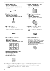
...PNWP3C160A Used to install and configure the camera. - PSHG1235Z Used to protect the camera from water … Sensor Range Cap (1 pc.) [BL-C160 Only] Order No. PQQX15704TCD Contains the Setup Program needed to configure the camera, as well as the camera's documentation.* *See the included Important...Information document) - 2 LAN cables (1 indoor cable and 1 outdoor cable) - PQHG10748Z Used to protect the camera from water … Self Bonding Tape (1pc.) Order No. a router 6 PNYCC160A Used to secure the camera when wall mounting it. … Power Transfer Unit (1 pc.) Order No....
...PNWP3C160A Used to install and configure the camera. - PSHG1235Z Used to protect the camera from water … Sensor Range Cap (1 pc.) [BL-C160 Only] Order No. PQQX15704TCD Contains the Setup Program needed to configure the camera, as well as the camera's documentation.* *See the included Important...Information document) - 2 LAN cables (1 indoor cable and 1 outdoor cable) - PQHG10748Z Used to protect the camera from water … Self Bonding Tape (1pc.) Order No. a router 6 PNYCC160A Used to secure the camera when wall mounting it. … Power Transfer Unit (1 pc.) Order No....
Installation Guide
Page 7
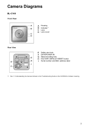
Camera Diagrams BL-C140 Front View A A Housing B B Indicator*1 C Lens D Lens cover C D Rear View E F E Safety wire hole F DATA/POWER IN G G Stand mounting hole H FACTORY DEFAULT RESET button H I Serial number and MAC address label I *1 See 1.1 Understanding the Camera Indicator in the Troubleshooting Guide on the CD-ROM for indicator meaning. 7
Camera Diagrams BL-C140 Front View A A Housing B B Indicator*1 C Lens D Lens cover C D Rear View E F E Safety wire hole F DATA/POWER IN G G Stand mounting hole H FACTORY DEFAULT RESET button H I Serial number and MAC address label I *1 See 1.1 Understanding the Camera Indicator in the Troubleshooting Guide on the CD-ROM for indicator meaning. 7
Installation Guide
Page 8
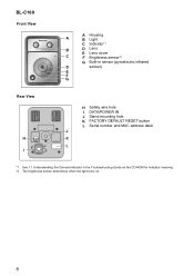
BL-C160 Front View A Housing A B Light C Indicator*1 B D Lens E Lens cover C F Brightness sensor*2 G Built-in sensor (pyroelectric infrared D sensor) E F G Rear View H I H Safety wire hole I DATA/POWER IN J Stand mounting hole K FACTORY DEFAULT RESET button L Serial number and MAC address label J K L *1 See 1.1 Understanding the Camera Indicator in the Troubleshooting Guide on the CD-ROM for indicator meaning. *2 The brightness sensor determines when the light turns on. 8
BL-C160 Front View A Housing A B Light C Indicator*1 B D Lens E Lens cover C F Brightness sensor*2 G Built-in sensor (pyroelectric infrared D sensor) E F G Rear View H I H Safety wire hole I DATA/POWER IN J Stand mounting hole K FACTORY DEFAULT RESET button L Serial number and MAC address label J K L *1 See 1.1 Understanding the Camera Indicator in the Troubleshooting Guide on the CD-ROM for indicator meaning. *2 The brightness sensor determines when the light turns on. 8
Installation Guide
Page 9
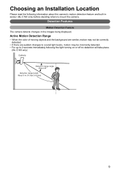
... range angle About 45q Detection range length About 5 m (16 feet 5 inches) 9 Detection Features Motion Detection Feature The camera detects changes in sensor (BL-C160 only) before deciding where to 2 seconds immediately following information about the camera's motion detection feature and built-in the images being displayed. Active Motion Detection Range • When the..., motion may not be correctly detected. • If there are sudden changes to overall light levels, motion may be incorrectly detected. • For up to mount the camera.
... range angle About 45q Detection range length About 5 m (16 feet 5 inches) 9 Detection Features Motion Detection Feature The camera detects changes in sensor (BL-C160 only) before deciding where to 2 seconds immediately following information about the camera's motion detection feature and built-in the images being displayed. Active Motion Detection Range • When the..., motion may not be correctly detected. • If there are sudden changes to overall light levels, motion may be incorrectly detected. • For up to mount the camera.
Installation Guide
Page 11
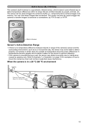
...detection. • If the camera is mounted facing a road, the sensor may not be used to trigger the camera to transfer images to interference caused by passing cars. When the camera is in a 20 °C (68 °F) environment Camera Detection range angle About 20q ...Detection range length About 5 m (16 feet 5 inches) 11 Built-in Sensor (BL-C160 Only) The camera...
...detection. • If the camera is mounted facing a road, the sensor may not be used to trigger the camera to transfer images to interference caused by passing cars. When the camera is in a 20 °C (68 °F) environment Camera Detection range angle About 20q ...Detection range length About 5 m (16 feet 5 inches) 11 Built-in Sensor (BL-C160 Only) The camera...
Installation Guide
Page 13
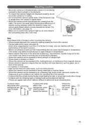
...8226; Make sure to position the camera's light so as not to disturb the surrounding area. (BL-C160 only) Built-in sensor Note Avoid these kinds of locations when mounting the camera. • Where people approach the camera by walking toward the front of the camera • Facing roads where many cars... with heat detection, such as mobile phones • Where the camera can be exposed to strong chemicals or noxious fumes • Where the camera can be exposed to fire, heating devices, or interference from the sides. If the Panasonic logo is upside down, the camera is upside down .
...8226; Make sure to position the camera's light so as not to disturb the surrounding area. (BL-C160 only) Built-in sensor Note Avoid these kinds of locations when mounting the camera. • Where people approach the camera by walking toward the front of the camera • Facing roads where many cars... with heat detection, such as mobile phones • Where the camera can be exposed to strong chemicals or noxious fumes • Where the camera can be exposed to fire, heating devices, or interference from the sides. If the Panasonic logo is upside down, the camera is upside down .
Installation Guide
Page 15
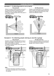
...garage will be difficult to detect. Not Recommend People or cars passing by on the street are easy to detect, but people approaching the camera by on the street will be easy to detect, but people or cars passing by on your property Recommend Where it is easy to detect... can view over parked cars, or other objects in front of the camera are difficult to detect. Difficult to detect Street Easy to detect Street Easy to detect Camera Easy to detect Difficult to detect Note • Cameras should be mounted so that they pass in the garage. Installation Examples Example 1: For ...
...garage will be difficult to detect. Not Recommend People or cars passing by on the street are easy to detect, but people approaching the camera by on the street will be easy to detect, but people or cars passing by on your property Recommend Where it is easy to detect... can view over parked cars, or other objects in front of the camera are difficult to detect. Difficult to detect Street Easy to detect Street Easy to detect Camera Easy to detect Difficult to detect Note • Cameras should be mounted so that they pass in the garage. Installation Examples Example 1: For ...
Installation Guide
Page 18
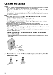
... the power transfer unit. • Use screws that are for the material of the wall, such as a column, otherwise the camera may damage the camera's image sensor. Camera Mounting Caution • Do not drive the screws into a secure area of the wall. • The included screws are appropriate for use...can cause the built-in sensor before deciding where to install the camera. 1 Secure the safety wire to prevent the camera from falling. Safety wire Washer S Screw B 2 Remove the tab on the flexible stand, then pass an outdoor LAN cable through the ground, do not connect cables under the ...
... the power transfer unit. • Use screws that are for the material of the wall, such as a column, otherwise the camera may damage the camera's image sensor. Camera Mounting Caution • Do not drive the screws into a secure area of the wall. • The included screws are appropriate for use...can cause the built-in sensor before deciding where to install the camera. 1 Secure the safety wire to prevent the camera from falling. Safety wire Washer S Screw B 2 Remove the tab on the flexible stand, then pass an outdoor LAN cable through the ground, do not connect cables under the ...
Installation Guide
Page 19
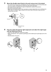
... stand firmly to nip the cable. • Make sure the flexible stand is firmly mounted on the other side of material the camera is pointing up when attaching the right-angle joint to make sure the camera does not drop. Screw A At least 25 mm (1 inch) 4 Pass the cable through the right-... clicks into a soft material. Drive the screws into a secure area of the wall, such as a column, otherwise the camera may fall and be damaged. • Use screws that the "↑UP" symbol is mounted to. • Be careful not to the wall using screw A (included). • Do not drive the screws into...
... stand firmly to nip the cable. • Make sure the flexible stand is firmly mounted on the other side of material the camera is pointing up when attaching the right-angle joint to make sure the camera does not drop. Screw A At least 25 mm (1 inch) 4 Pass the cable through the right-... clicks into a soft material. Drive the screws into a secure area of the wall, such as a column, otherwise the camera may fall and be damaged. • Use screws that the "↑UP" symbol is mounted to. • Be careful not to the wall using screw A (included). • Do not drive the screws into...
Installation Guide
Page 20
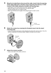
Threaded mount Grip 7 Adjust the camera position. • Leave some slack in the cable, as shown. • Stretch the tape to twice its length when you wrap...there are no gaps in the wrapped tape for water to enter. 50 mm (1 15/16 inches) 6 Attach the camera by screwing the threaded mount into the stand mounting hole. • Loosen the flexible stand grip to the desired angle, retighten the grip firmly into place. 5 Wrap the... included self bonding tape. • Leave about 10 mm (3/8 inches) of the foam exposed, as shown. 20 Once the camera is adjusted to make adjusting the angle of the...
Threaded mount Grip 7 Adjust the camera position. • Leave some slack in the cable, as shown. • Stretch the tape to twice its length when you wrap...there are no gaps in the wrapped tape for water to enter. 50 mm (1 15/16 inches) 6 Attach the camera by screwing the threaded mount into the stand mounting hole. • Loosen the flexible stand grip to the desired angle, retighten the grip firmly into place. 5 Wrap the... included self bonding tape. • Leave about 10 mm (3/8 inches) of the foam exposed, as shown. 20 Once the camera is adjusted to make adjusting the angle of the...
Installation Guide
Page 21
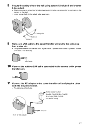
To the power outlet (For BL-C140CE/BL-C140E/ BL-C160CE/BL-C160E use an anchor to help secure the camera to the wall. • Leave some slack in place with 2 pieces from screw A (4 mm x 20 mm [3/16 inch x 13/16 inch]). Safety wire Washer L Screw A 9 ... outdoor LAN cable connected to the camera to the power transfer unit. 11 Connect the AC adaptor to the switching hub, router, etc. • The power transfer unit can be fixed in the safety wire, as shown. 8 Secure the safety wire to the wall using screw A (included) and washer L (included). • When mounting...
To the power outlet (For BL-C140CE/BL-C140E/ BL-C160CE/BL-C160E use an anchor to help secure the camera to the wall. • Leave some slack in place with 2 pieces from screw A (4 mm x 20 mm [3/16 inch x 13/16 inch]). Safety wire Washer L Screw A 9 ... outdoor LAN cable connected to the camera to the power transfer unit. 11 Connect the AC adaptor to the switching hub, router, etc. • The power transfer unit can be fixed in the safety wire, as shown. 8 Secure the safety wire to the wall using screw A (included) and washer L (included). • When mounting...

Installation Guide
Page 22
... on a mortar or concrete surface • Prepare anchors for 4 mm (3/16 inch) diameter screws for tile) C Mount the flexible stand using the screws. 22 Be careful of pieces of tile, use a drill for mounting. Drill for concrete (in case of mortar which may become loose and fall. B Make holes with a hammer...8226; Mortar walls break easily when drilling. Insert anchors (customer-provided) into the holes and push them inside the holes with an electric drill. When mounting on the wall where you plan to mount the flexible stand and mark the points where you are going to make holes.
... on a mortar or concrete surface • Prepare anchors for 4 mm (3/16 inch) diameter screws for tile) C Mount the flexible stand using the screws. 22 Be careful of pieces of tile, use a drill for mounting. Drill for concrete (in case of mortar which may become loose and fall. B Make holes with a hammer...8226; Mortar walls break easily when drilling. Insert anchors (customer-provided) into the holes and push them inside the holes with an electric drill. When mounting on the wall where you plan to mount the flexible stand and mark the points where you are going to make holes.