
Installation Guide
Page 1
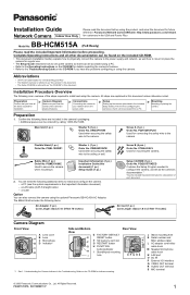
... 1.8 m (5 feet 11 inches) Camera Diagram Front View A Lens cover A B Lens C Microphone B D Indicator*1 C D Side and Bottom View E F G H I E FACTORY DEFAULT RESET button F SD memory card slot G RESTART button H FUNCTION button/indicator I /O interface Q VIDEO OUT terminal R AUDIO OUT terminal S MIC terminal © 2006 Panasonic Communications Co., Ltd. Installation Procedure Overview The following items are explained in the camera's packaging. • Additional pieces can be accessed using the camera. This involves configuring the camera so that you know...
... 1.8 m (5 feet 11 inches) Camera Diagram Front View A Lens cover A B Lens C Microphone B D Indicator*1 C D Side and Bottom View E F G H I E FACTORY DEFAULT RESET button F SD memory card slot G RESTART button H FUNCTION button/indicator I /O interface Q VIDEO OUT terminal R AUDIO OUT terminal S MIC terminal © 2006 Panasonic Communications Co., Ltd. Installation Procedure Overview The following items are explained in the camera's packaging. • Additional pieces can be accessed using the camera. This involves configuring the camera so that you know...
Installation Guide
Page 2
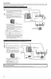
... take time for the PoE hub's indicators to light green. • The indicator display differs depending on manufacturers, refer to the Panasonic Network Camera website (http://panasonic.co.jp/pcc/products/en/netwkcam/) for connection instructions • The lens will pan and tilt when the camera is connected to a LAN port of the PoE hub and to your router and can access the Internet. BB-HCA3A). • When the lens pans or tilts, a sound can...
... take time for the PoE hub's indicators to light green. • The indicator display differs depending on manufacturers, refer to the Panasonic Network Camera website (http://panasonic.co.jp/pcc/products/en/netwkcam/) for connection instructions • The lens will pan and tilt when the camera is connected to a LAN port of the PoE hub and to your router and can access the Internet. BB-HCA3A). • When the lens pans or tilts, a sound can...
Installation Guide
Page 3
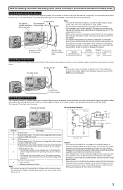
... degradation in the event of the terminal 4. Audio may be connected to this in the Operating Instructions on the CDROM for example, turning a light on the CD-ROM. DC power output terminal. 4 • 10.5-13 V DC • Maximum load drive is 100 mA. Audio distortion will be controlled. 3 The external I /O interface Circuit Diagram Example Camera Relay Light 12 V* 4 3 Door Sensor 2 (Alarm 2) 2 G Door Sensor 1 (Alarm 1) 1 G Terminal Description...
... degradation in the event of the terminal 4. Audio may be connected to this in the Operating Instructions on the CDROM for example, turning a light on the CD-ROM. DC power output terminal. 4 • 10.5-13 V DC • Maximum load drive is 100 mA. Audio distortion will be controlled. 3 The external I /O interface Circuit Diagram Example Camera Relay Light 12 V* 4 3 Door Sensor 2 (Alarm 2) 2 G Door Sensor 1 (Alarm 1) 1 G Terminal Description...
Installation Guide
Page 4
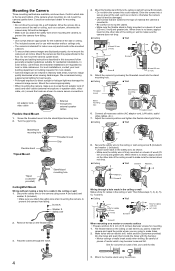
... not mount the camera upside down . Screw the threaded mount into a soft material. Turn the grip firmly. Connect all necessary cables (AC adaptor cord, LAN cable, audio/ video cables, etc.). 7. Adjust the camera position and tighten the flexible stand grip firmly. Secure the safety wire to the ceiling or wall using supplemental lighting for best results. • Prolonged exposure to direct sunlight or halogen light may damage the camera's image sensor...
... not mount the camera upside down . Screw the threaded mount into a soft material. Turn the grip firmly. Connect all necessary cables (AC adaptor cord, LAN cable, audio/ video cables, etc.). 7. Adjust the camera position and tighten the flexible stand grip firmly. Secure the safety wire to the ceiling or wall using supplemental lighting for best results. • Prolonged exposure to direct sunlight or halogen light may damage the camera's image sensor...


