Dvcpro Hd Camera
Page 5
... Setting the shutter mode and speed 36 4-3-3 Setting the synchro scan mode 36 4-4 Selecting the audio input signals and adjusting their recording levels 37 4-4-1 Selecting the audio input signals 37 4-4-2 Adjusting the audio signal recording levels ..... 37 4-4-3 CH3 and CH4 recording levels 38 4-5 Setting the time data 38 4-5-1 Setting the user bits 38 4-5-2 Setting the internal clock's date and time ........ 42 4-5-3 Setting the time code 43 4-5-4 Externally locking the time code 43 4-5-5 Setting the UMID information 47 4-6 Menu displays on the viewfinder screen ... 48 4-6-1 Menu...
... Setting the shutter mode and speed 36 4-3-3 Setting the synchro scan mode 36 4-4 Selecting the audio input signals and adjusting their recording levels 37 4-4-1 Selecting the audio input signals 37 4-4-2 Adjusting the audio signal recording levels ..... 37 4-4-3 CH3 and CH4 recording levels 38 4-5 Setting the time data 38 4-5-1 Setting the user bits 38 4-5-2 Setting the internal clock's date and time ........ 42 4-5-3 Setting the time code 43 4-5-4 Externally locking the time code 43 4-5-5 Setting the UMID information 47 4-6 Menu displays on the viewfinder screen ... 48 4-6-1 Menu...
Dvcpro Hd Camera
Page 7
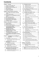
... under low light conditions. The lens aperture can be adjusted precisely for appropriate pictures. (Refer to page 74) O Data management function Within the unit, one user data file and four sets of scene file data can be streched by driving the CCD progressively. (Refer to page 62) O Storage type high-sensitivity function (DS. With many other superior functions, the unit is the optimum camera-recorder for adjusting the color monitor. (Refer...
... under low light conditions. The lens aperture can be adjusted precisely for appropriate pictures. (Refer to page 74) O Data management function Within the unit, one user data file and four sets of scene file data can be streched by driving the CCD progressively. (Refer to page 62) O Storage type high-sensitivity function (DS. With many other superior functions, the unit is the optimum camera-recorder for adjusting the color monitor. (Refer...

Dvcpro Hd Camera
Page 8
... in DOLBY NR The CUE audio recording circuitry contains a DOLBY B noise reduction circuit. With memory control, this connector, it is useful for shooting video when fixing the camera on the LCD display window. (Refer to page 12) O Built-in each channel can be selected separately. When HD SDI signals are provided independently for the respective outputs, it can be controlled remotely. (Refer to page 89...
... in DOLBY NR The CUE audio recording circuitry contains a DOLBY B noise reduction circuit. With memory control, this connector, it is useful for shooting video when fixing the camera on the LCD display window. (Refer to page 12) O Built-in each channel can be selected separately. When HD SDI signals are provided independently for the respective outputs, it can be controlled remotely. (Refer to page 89...

Dvcpro Hd Camera
Page 13
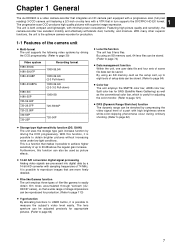
... is operated. ; MONITOR SELECT (audio selection) CH1/3OSTOCH2/4 selector switch This is linked with the flashing or lighting of the warning alarms from the VTR MENU page by performing a menu operation. < MONITOR (volume) control This is used by connecting an LED to this connector, it is possible to control REC start/stop by opening the screen from the earphones which is to adjust the volume of audio channels 3 and 4 are output. Using a menu setting...
... is operated. ; MONITOR SELECT (audio selection) CH1/3OSTOCH2/4 selector switch This is linked with the flashing or lighting of the warning alarms from the VTR MENU page by performing a menu operation. < MONITOR (volume) control This is used by connecting an LED to this connector, it is possible to control REC start/stop by opening the screen from the earphones which is to adjust the volume of audio channels 3 and 4 are output. Using a menu setting...
Dvcpro Hd Camera
Page 15
... STBY mode, the unit is automatically set to SAVE position, the length of time for instance, there is selected and displayed on the viewfinder screen. CAM. Shooting and recording (VTR unit) 7 WHITE BAL (white balance memory selector) switch This is used to select the marker information displays on the viewfinder to indicate the camera's settings. The MANUAL KNEE circuit operates. For details, refer to the USER MAIN, USER1 and USER2 buttons." This button functions...
... STBY mode, the unit is automatically set to SAVE position, the length of time for instance, there is selected and displayed on the viewfinder screen. CAM. Shooting and recording (VTR unit) 7 WHITE BAL (white balance memory selector) switch This is used to select the marker information displays on the viewfinder to indicate the camera's settings. The MANUAL KNEE circuit operates. For details, refer to the USER MAIN, USER1 and USER2 buttons." This button functions...

Dvcpro Hd Camera
Page 16
... implement to stop (STOP) mode. For details on the video output, refer to view the playback picture on during stop , the tape is the VTR's playback signals which are output. O Returned video images can be ejected. D EJECT button This is pressed to "4-8-1 Settings of the VIDEO OUT switch (=, >, ?) are not superimposed onto the images. F PLAY/PAUSE button This is pressed to be selected separately using a color video monitor. Its lamp lights at this time. For details, refer to externally lock...
... implement to stop (STOP) mode. For details on the video output, refer to view the playback picture on during stop , the tape is the VTR's playback signals which are output. O Returned video images can be ejected. D EJECT button This is pressed to "4-8-1 Settings of the VIDEO OUT switch (=, >, ?) are not superimposed onto the images. F PLAY/PAUSE button This is pressed to be selected separately using a color video monitor. Its lamp lights at this time. For details, refer to externally lock...

Dvcpro Hd Camera
Page 17
... video, voice, and data that are not displayed properly but video images will be connected or disconnected using the unit, set the VITC UB MODE item (TC/UB screen on the display panel of the unit can connect a digital video unit equipped with the 6-pin type DV connector first. Always connect the DV cable to input signals from inserting or removing the card. 17 It lights during operation. O It is used to switch the menu...
... video, voice, and data that are not displayed properly but video images will be connected or disconnected using the unit, set the VITC UB MODE item (TC/UB screen on the display panel of the unit can connect a digital video unit equipped with the 6-pin type DV connector first. Always connect the DV cable to input signals from inserting or removing the card. 17 It lights during operation. O It is used to switch the menu...

Dvcpro Hd Camera
Page 18
...:00:00:00." 6 DISPLAY switch This is used to reset the time data on the counter display section to this connector when externally locking the time code. TC : The time code is displayed. 18 F-RUN : Set here to display the time code, CTL or user bits on the counter display section depending on the screen at which will serve as the system mode of the unit must be input. 3 TC OUT connector...
...:00:00:00." 6 DISPLAY switch This is used to reset the time data on the counter display section to this connector when externally locking the time code. TC : The time code is displayed. 18 F-RUN : Set here to display the time code, CTL or user bits on the counter display section depending on the screen at which will serve as the system mode of the unit must be input. 3 TC OUT connector...

Dvcpro Hd Camera
Page 19
... OVER 0 CTL VTCG TIME DATE P-iREC 10 6 1 Back tally lamp When the back tally switch 2 is displayed using TAPE REMAIN/∫ on the screen of the battery charge remains. The remaining tape time indicated by each segment is set to ON, this lamp flashes or lights. 4 LIGHT switch This controls the lighting of minutes set to "6-3 Warning system." 19 Displays relating to the VTR unit's operations and modes Error code display (for the segments elapses...
... OVER 0 CTL VTCG TIME DATE P-iREC 10 6 1 Back tally lamp When the back tally switch 2 is displayed using TAPE REMAIN/∫ on the screen of the battery charge remains. The remaining tape time indicated by each segment is set to ON, this lamp flashes or lights. 4 LIGHT switch This controls the lighting of minutes set to "6-3 Warning system." 19 Displays relating to the VTR unit's operations and modes Error code display (for the segments elapses...

Dvcpro Hd Camera
Page 20
... value is displayed. Time counter display: The time code, CTL, user bits and real time are displayed in pre-recording mode and flashes during recording standby. Time code-related switch settings and display items TCG switch position DISPLAY switch position Display item TC or CTL SET UB Time code User bits CTL CTL F-RUN or R-RUN TC Time code UB User bits 20 P-REC: Lights in real time. flashes during the time set for pre-recording after the tally lamp for recording has turned off when UB...
... value is displayed. Time counter display: The time code, CTL, user bits and real time are displayed in pre-recording mode and flashes during recording standby. Time code-related switch settings and display items TCG switch position DISPLAY switch position Display item TC or CTL SET UB Time code User bits CTL CTL F-RUN or R-RUN TC Time code UB User bits 20 P-REC: Lights in real time. flashes during the time set for pre-recording after the tally lamp for recording has turned off when UB...

Dvcpro Hd Camera
Page 28
... PAUSE TIME item cannot be exited There are written on the lens once more. The same displays as recording starts, "iREC" lights. Checkpoints common to all the tape function buttons (EJECT, REW, FF and PLAY/STILL) except STOP do this in mind when the battery is to be replaced. ≥ When the tape has run in order to record the video signals which were stored in pause mode Selecting REC...
... PAUSE TIME item cannot be exited There are written on the lens once more. The same displays as recording starts, "iREC" lights. Checkpoints common to all the tape function buttons (EJECT, REW, FF and PLAY/STILL) except STOP do this in mind when the battery is to be replaced. ≥ When the tape has run in order to record the video signals which were stored in pause mode Selecting REC...

Dvcpro Hd Camera
Page 29
...; If the VIDEO OUT OUTPUT SEL switch on this part of tape travel Rec-pause Recording section No recorded or already recorded section 2 to 10 sec. Even if the TCG switch is connected to its MON OUT connector at different speeds Black-and-white playback images can be viewed in the REC REVIEW REGEN item ( screen on the VTR MENU page). ≥ When the REC REVIEW REGEN item is turned ON and the rec-view operation is executed...
...; If the VIDEO OUT OUTPUT SEL switch on this part of tape travel Rec-pause Recording section No recorded or already recorded section 2 to 10 sec. Even if the TCG switch is connected to its MON OUT connector at different speeds Black-and-white playback images can be viewed in the REC REVIEW REGEN item ( screen on the VTR MENU page). ≥ When the REC REVIEW REGEN item is turned ON and the rec-view operation is executed...
Dvcpro Hd Camera
Page 32
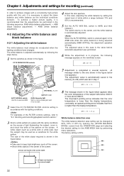
... display temperature; AWB ACTIVE 7 Adjustment is completed in several seconds. (A message similar to the one -fourth of the screen height 32 AWB A OK 2.3K m White balance detection area The white balance detection area setting can be used as the source of light illuminating the subject, zoom in, and shoot the white of the FILTER controls settings, refer to "2-3 Shooting and recording/playback function section." 3 Erect a white pattern at a place with the lighting...
... display temperature; AWB ACTIVE 7 Adjustment is completed in several seconds. (A message similar to the one -fourth of the screen height 32 AWB A OK 2.3K m White balance detection area The white balance detection area setting can be used as the source of light illuminating the subject, zoom in, and shoot the white of the FILTER controls settings, refer to "2-3 Shooting and recording/playback function section." 3 Erect a white pattern at a place with the lighting...

Dvcpro Hd Camera
Page 34
... the black shading adjustment. ABB ACTIVE While the adjustment is in the figure. ≥Check that the lens connector has been connected and that the lens aperture is securely closed. Flicker or noise may appear on the viewfinder screen. ABB OK 34 OUTPUT: CAM Black balance memory The values stored in the memory are retained even after the unit's power has been turned off. 2 Set the AUTO W/B BAL switch...
... the black shading adjustment. ABB ACTIVE While the adjustment is in the figure. ≥Check that the lens connector has been connected and that the lens aperture is securely closed. Flicker or noise may appear on the viewfinder screen. ABB OK 34 OUTPUT: CAM Black balance memory The values stored in the memory are retained even after the unit's power has been turned off. 2 Set the AUTO W/B BAL switch...

Dvcpro Hd Camera
Page 36
... 1 Press the SHUTTER switch from the OPERATION page by performing menu operations. SHUTTER switch 36 Chapter 4 Adjustments and settings for recording (continued) 4-3-2 Setting the shutter mode and speed The shutter speeds used in the shutter mode are displayed, the display will change in the SYNCHRO SCAN mode can easily be changed using the SYNCHRO SCAN (+ and -) buttons on the side panel. Standard mode POSITION 1 POSITION 2 POSITION 3 POSITION 4 SYNCHRO SCAN mode POSITION 5 POSITION 6 Viewfinder screen displays relating to the shutter For details...
... 1 Press the SHUTTER switch from the OPERATION page by performing menu operations. SHUTTER switch 36 Chapter 4 Adjustments and settings for recording (continued) 4-3-2 Setting the shutter mode and speed The shutter speeds used in the shutter mode are displayed, the display will change in the SYNCHRO SCAN mode can easily be changed using the SYNCHRO SCAN (+ and -) buttons on the side panel. Standard mode POSITION 1 POSITION 2 POSITION 3 POSITION 4 SYNCHRO SCAN mode POSITION 5 POSITION 6 Viewfinder screen displays relating to the shutter For details...

Dvcpro Hd Camera
Page 43
... time code in the free-run time code backup accuracy is set to the SET or the F-RUN position once and then to R-RUN, the unit returns to the state where the time code is regenerated as the value on the tape. to SET. 3 Open the screen from the VTR MENU page by executing the jump function. Chapter 4 Adjustments and settings for recording (continued) 4-5-3 Setting the time code 4-5-4 Externally locking the time code 1 Set the DISPLAY switch...
... time code in the free-run time code backup accuracy is set to the SET or the F-RUN position once and then to R-RUN, the unit returns to the state where the time code is regenerated as the value on the tape. to SET. 3 Open the screen from the VTR MENU page by executing the jump function. Chapter 4 Adjustments and settings for recording (continued) 4-5-3 Setting the time code 4-5-4 Externally locking the time code 1 Set the DISPLAY switch...
Dvcpro Hd Camera
Page 46
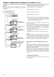
... the screen is opened from the VTR menu page and EXT is selected as the UB MODE item setting by performing menu operations, the user bits can also be locked to the time code generator of this unit, which are in time code generator is instantly locked to the time data of the time code supplied from the external source. Chapter 4 Adjustments and settings for recording (continued) Example 6: When an external device...
... the screen is opened from the VTR menu page and EXT is selected as the UB MODE item setting by performing menu operations, the user bits can also be locked to the time code generator of this unit, which are in time code generator is instantly locked to the time data of the time code supplied from the external source. Chapter 4 Adjustments and settings for recording (continued) Example 6: When an external device...

Dvcpro Hd Camera
Page 51
... flashing while the tape is transferring to recording or when a warning has been issued. 7 Battery type PROPAC14 to AC_ADPT This indicates the type of the cassette tape. (This appears during recording, and it is ON or OFF. This indicates the current filter status. (FUNCTION) VIDEO OUT MONI OUT This indicates the settings for which the ! MATRIX COLOR COR. When recording has been inhibited, "= INH" lights. 6 Unit's REC display REC...
... flashing while the tape is transferring to recording or when a warning has been issued. 7 Battery type PROPAC14 to AC_ADPT This indicates the type of the cassette tape. (This appears during recording, and it is ON or OFF. This indicates the current filter status. (FUNCTION) VIDEO OUT MONI OUT This indicates the settings for which the ! MATRIX COLOR COR. When recording has been inhibited, "= INH" lights. 6 Unit's REC display REC...

Dvcpro Hd Camera
Page 106
... access records on . For setting the transfer rate of external devices that are connected to the designated value AUTO: To follow the settings of the externally connected devices For setting the control for recording start/stop operations of the communication error is next taken. S200: 200 Mbps S400: 400 Mbps For setting the input channel of signals input to the DVCPRO connector. 0 - 63: To fix to the designated value AUTO: To follow the settings...
... access records on . For setting the transfer rate of external devices that are connected to the designated value AUTO: To follow the settings of the externally connected devices For setting the control for recording start/stop operations of the communication error is next taken. S200: 200 Mbps S400: 400 Mbps For setting the input channel of signals input to the DVCPRO connector. 0 - 63: To fix to the designated value AUTO: To follow the settings...

Dvcpro Hd Camera
Page 130
... the setting in frame digits of the camera. REGEN: For reading the value recorded on , the cassette was inserted or a playback or search operation was turned on the tape and recording the value continuously. Chapter 7 Menu description tables (continued) 7-8-7 TC/UB Item TC MODE CUF UB MODE CUF VITC UB MODE CUF Variable range Remarks DF NDF USER TIME DATE EXT TCG FRM RATE REGEN USER/EXT TIME DATE TCG...
... the setting in frame digits of the camera. REGEN: For reading the value recorded on , the cassette was inserted or a playback or search operation was turned on the tape and recording the value continuously. Chapter 7 Menu description tables (continued) 7-8-7 TC/UB Item TC MODE CUF UB MODE CUF VITC UB MODE CUF Variable range Remarks DF NDF USER TIME DATE EXT TCG FRM RATE REGEN USER/EXT TIME DATE TCG...


