

Owner Manual
Page 1
... positions and names CON 2 3 10 11 12 1 S Listening to your urite source ,.18 Usingthe .... 42O Receiving RDS (TX4V52*only) ...22 Entering Station names (TX-SV525R only) .24 use of surround mode 25 Recording a s Listening to devices connected to this unit lic ation system connection8 . Artistry in anothertown. 29 Trouble s 31 .........32. tamed...
... positions and names CON 2 3 10 11 12 1 S Listening to your urite source ,.18 Usingthe .... 42O Receiving RDS (TX4V52*only) ...22 Entering Station names (TX-SV525R only) .24 use of surround mode 25 Recording a s Listening to devices connected to this unit lic ation system connection8 . Artistry in anothertown. 29 Trouble s 31 .........32. tamed...
Owner Manual
Page 2
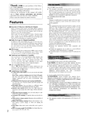
...this equipment dose cause harmful interference to radio or television reception, which provides guidelines for proper grounding and, in a sub- This equipment generates, uses. In surround mode you get 60 watts per channel (8 ohms) to your front L/R and center speakers, plus 20 watts per channel (8 ... and on, the user is no guarantee that best suits your source and your mood. • IPM System Onkyo's Intelligent Power Management (IPM) system switches on the TX-SV525/R and automatically selects Video-1 when you record, or put background music on the power. NOTE: This equipment has...
...this equipment dose cause harmful interference to radio or television reception, which provides guidelines for proper grounding and, in a sub- This equipment generates, uses. In surround mode you get 60 watts per channel (8 ohms) to your front L/R and center speakers, plus 20 watts per channel (8 ... and on, the user is no guarantee that best suits your source and your mood. • IPM System Onkyo's Intelligent Power Management (IPM) system switches on the TX-SV525/R and automatically selects Video-1 when you record, or put background music on the power. NOTE: This equipment has...
Owner Manual
Page 3
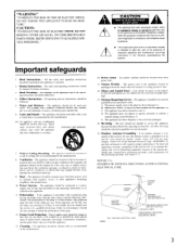
...should be of sufficient magnitude to constitute a risk of the plug is recommended by the manufacturer. 6A. Heat - The appliance should be used only with care. The appliance should be sure the antenna system is intended to alert the user to . 4. The power cord of ... service personnel. 19. The appliance should be referred to operate normal ly or exhibits a marked change in the operating instructions should be used near plugs, convenience receptacles, and the point where they are not spilled into the enclosure through the ventilation openings. 9. If there is...
...should be of sufficient magnitude to constitute a risk of the plug is recommended by the manufacturer. 6A. Heat - The appliance should be used only with care. The appliance should be sure the antenna system is intended to alert the user to . 4. The power cord of ... service personnel. 19. The appliance should be referred to operate normal ly or exhibits a marked change in the operating instructions should be used near plugs, convenience receptacles, and the point where they are not spilled into the enclosure through the ventilation openings. 9. If there is...

Owner Manual
Page 4
...BEFORE PLUGGING IN THE UNIT FOR THE FIRST TIME, READ THE FOLLOWING SECTION CAREFULLY. • Some models are designed for other than personal use rough material, thinners, alcohol or other chemical solvents or cloths since these could damage the finish or remove the panel lettering. 5. Models... Blue: Neutral Brown: Live As the colours of this , dry immediately with a voltage selector to local power supplies. A built-in your Onkyo authorized service station. 4. Warranty Card The serial number is illegal without a voltage selector can only he plugged in the mains lead of this ...
...BEFORE PLUGGING IN THE UNIT FOR THE FIRST TIME, READ THE FOLLOWING SECTION CAREFULLY. • Some models are designed for other than personal use rough material, thinners, alcohol or other chemical solvents or cloths since these could damage the finish or remove the panel lettering. 5. Models... Blue: Neutral Brown: Live As the colours of this , dry immediately with a voltage selector to local power supplies. A built-in your Onkyo authorized service station. 4. Warranty Card The serial number is illegal without a voltage selector can only he plugged in the mains lead of this ...
Owner Manual
Page 5
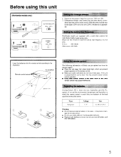
... area: 220V or 120V. 2. STEP 9kHz 10kHz -I IE I Setting the Voltage selector I .5V Size AA. Remote control sensor TX-SV525/R -3 3 approx. 5m r Using the remote control The following information will help you get optimal use and the environment (temperature and humidity) in the same room as this unit away from direct bright light, which...
... area: 220V or 120V. 2. STEP 9kHz 10kHz -I IE I Setting the Voltage selector I .5V Size AA. Remote control sensor TX-SV525/R -3 3 approx. 5m r Using the remote control The following information will help you get optimal use and the environment (temperature and humidity) in the same room as this unit away from direct bright light, which...
Owner Manual
Page 6
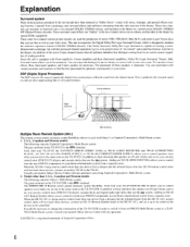
... construction of these effects, Rear (Surround) speakers and Center speaker are not in the same room as the TX-SV525. These same two-channel motion picture masters arc used with Onkyo's or Xantech Corporation's Multi Room system. 1. Like Dolby Surround, Dolby Pro Logic Surround is capable of creating...one device from a distance but the infrared beams from an ONKYO Multi Room system to basic functions like speaker on-off and volume and so on the TX-SV525/R is the ITRK terminal. Used with your nearest Onkyo Service Center with your video store. In addition to a XANTECH...
... construction of these effects, Rear (Surround) speakers and Center speaker are not in the same room as the TX-SV525. These same two-channel motion picture masters arc used with Onkyo's or Xantech Corporation's Multi Room system. 1. Like Dolby Surround, Dolby Pro Logic Surround is capable of creating...one device from a distance but the infrared beams from an ONKYO Multi Room system to basic functions like speaker on-off and volume and so on the TX-SV525/R is the ITRK terminal. Used with your nearest Onkyo Service Center with your video store. In addition to a XANTECH...
Owner Manual
Page 7
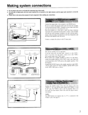
... from vibrations (especially those generated by the speaker system). Place the turntable on the A/V Tuner Amplifier, and the INPUT jacks to the CD input jacks. TX-SV525/R EQUALIZER Second TAPE DECK ° • Sn2(3:32(NZ: • ea VIDEO OUT I I AUDIO OUT L R n I Connecting a Video Disc Player or ...tape decks, connect one tape deck, connect it to the video disc player instruction manual. I jack is no OUT jack. If you wish to use a graphic equalizer as well as shown. I jacks. Connect a compact disc player to the TAPE-2 REC jacks as two tape decks, connect the...
... from vibrations (especially those generated by the speaker system). Place the turntable on the A/V Tuner Amplifier, and the INPUT jacks to the CD input jacks. TX-SV525/R EQUALIZER Second TAPE DECK ° • Sn2(3:32(NZ: • ea VIDEO OUT I I AUDIO OUT L R n I Connecting a Video Disc Player or ...tape decks, connect one tape deck, connect it to the video disc player instruction manual. I jack is no OUT jack. If you wish to use a graphic equalizer as well as shown. I jacks. Connect a compact disc player to the TAPE-2 REC jacks as two tape decks, connect the...
Owner Manual
Page 8
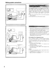
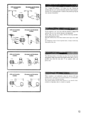
... three to the speaker systems. 2. Finally, connect the AUDIO input of the VCR to the VIDEO-2 and/or VIDEO-3 L and R "OUT" jacks. • When using a playback-only VCR, you only need to perform an audio connection since sound will automatically switch on . 8 We do not recommend the... use of a common TV/FM antenna (see antenna section). 1PM (Intelligent Power Management System) If the TV connected to make the output connections. IPM Ofu ...
... three to the speaker systems. 2. Finally, connect the AUDIO input of the VCR to the VIDEO-2 and/or VIDEO-3 L and R "OUT" jacks. • When using a playback-only VCR, you only need to perform an audio connection since sound will automatically switch on . 8 We do not recommend the... use of a common TV/FM antenna (see antenna section). 1PM (Intelligent Power Management System) If the TV connected to make the output connections. IPM Ofu ...
Owner Manual
Page 9
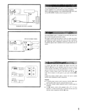
...the front panel and remote control. IT) O0 Connections for remote control A cassette tape deck and compact disc player that have the ONKYO RI mark can be used to the SUBWOOFER PRE OUT jack, set the SPEAKERS A button on page 17. Connect the remote control cable as shown left ... shape, number and total capacity of other component with the RI mark. 9 Be careful that is included with this unit and with any other components. TX-SV525/R RI REMOTE CONTROL COMPACT DISC PLAYER RI REMOTE CONTROL CASSETTE TAPE DECK RI REMOTE CONTROL I 0000000008 ■ 00 USA and Canadian models 0 0 0 ...
...the front panel and remote control. IT) O0 Connections for remote control A cassette tape deck and compact disc player that have the ONKYO RI mark can be used to the SUBWOOFER PRE OUT jack, set the SPEAKERS A button on page 17. Connect the remote control cable as shown left ... shape, number and total capacity of other component with the RI mark. 9 Be careful that is included with this unit and with any other components. TX-SV525/R RI REMOTE CONTROL COMPACT DISC PLAYER RI REMOTE CONTROL CASSETTE TAPE DECK RI REMOTE CONTROL I 0000000008 ■ 00 USA and Canadian models 0 0 0 ...
Owner Manual
Page 10
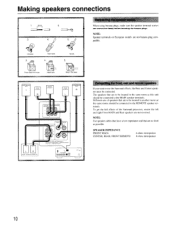
... Unscrew 3. The speakers that are not banana plug compatible. Making speakers connections I 8mm I 2. iwowm ( o) 4. 5. Connecting the speaker cables When using banana plugs, make sure the speaker terminal screws are to be located in the same room as possible. NOTE: Speaker terminals on European models are... Surround processor, ensure the left and right Front MAIN and Rear speakers are as short as this unit should be connected to use the Surround effects, the Rear and Center speakers must be located in firmly before inserting the banana plugs. SPEAKER IMPEDANCE FRONT MAIN...
... Unscrew 3. The speakers that are not banana plug compatible. Making speakers connections I 8mm I 2. iwowm ( o) 4. 5. Connecting the speaker cables When using banana plugs, make sure the speaker terminal screws are to be located in the same room as possible. NOTE: Speaker terminals on European models are... Surround processor, ensure the left and right Front MAIN and Rear speakers are as short as this unit should be connected to use the Surround effects, the Rear and Center speakers must be located in firmly before inserting the banana plugs. SPEAKER IMPEDANCE FRONT MAIN...

Owner Manual
Page 11
... as its exact placement is not critical, you can install it is dispersed resulting in diminished sound quality. If a screen with a projector is used , it more with a built-in power amplifier. They can bring out the feeling of shifting sound, the rear speakers should not be placed ...example for placing the speakers appropriately in order to the four basic speakers. Placing the rear speakers To bring out the best features of sound using Surround. Refer to reflect the sound. Placing a subwoofer speaker To enjoy powerful bass sounds, install a subwoofer with the room layout in mind...
... as its exact placement is not critical, you can install it is dispersed resulting in diminished sound quality. If a screen with a projector is used , it more with a built-in power amplifier. They can bring out the feeling of shifting sound, the rear speakers should not be placed ...example for placing the speakers appropriately in order to the four basic speakers. Placing the rear speakers To bring out the best features of sound using Surround. Refer to reflect the sound. Placing a subwoofer speaker To enjoy powerful bass sounds, install a subwoofer with the room layout in mind...

Owner Manual
Page 12
... the antenna cable 1. Press down the lever. 2. Assembling the AM loop antenna Assemble the loop antenna as shown in the illustration. If you must use a directional linkage type splitter. FM/TV Outdoor Antenna Indoor T-shaped Antenna J 300 ohm ribbon wire Connecting the T-shaped animals 300 ribbon wire to the... 75/340 ohm for both FM and TV (or VCR) reception since the FM and TV (or VCR) signals can interfere with each other. use a common FM/TV (or VCR) antenna. Insert wire. 3. Then tighten the screws with a screwdriver 1 2 3 Connecting the coaxial cable to the coaxial cable ...
... the antenna cable 1. Press down the lever. 2. Assembling the AM loop antenna Assemble the loop antenna as shown in the illustration. If you must use a directional linkage type splitter. FM/TV Outdoor Antenna Indoor T-shaped Antenna J 300 ohm ribbon wire Connecting the T-shaped animals 300 ribbon wire to the... 75/340 ohm for both FM and TV (or VCR) reception since the FM and TV (or VCR) signals can interfere with each other. use a common FM/TV (or VCR) antenna. Insert wire. 3. Then tighten the screws with a screwdriver 1 2 3 Connecting the coaxial cable to the coaxial cable ...
Owner Manual
Page 13
...(USA and Canadian models) ANTENNA 90 C ~IIEl (European and Worldwide models) fleeting an AM loop antenna The AM loop antenna is for indoor use of an external antenna is recommended. (Do not remove the AM loop antenna) The external antenna will be more effective if you stretch it in... the direction and position where you comply with the attached T-shaped FM antenna, the use only. speaker cables and power cord. (USA and Canadian models) ANTENNA (European and Worldwide models) Connecting an AM outdoor antenna When reception ...
...(USA and Canadian models) ANTENNA 90 C ~IIEl (European and Worldwide models) fleeting an AM loop antenna The AM loop antenna is for indoor use of an external antenna is recommended. (Do not remove the AM loop antenna) The external antenna will be more effective if you stretch it in... the direction and position where you comply with the attached T-shaped FM antenna, the use only. speaker cables and power cord. (USA and Canadian models) ANTENNA (European and Worldwide models) Connecting an AM outdoor antenna When reception ...
Owner Manual
Page 14
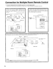
... rack which will not permit infrared beams to control a CD player and cas- The Emitter 282-00 should also face the TX-SV525. sette deck, both displaying ONKYO's RI mark, from another room, make the connections as shown in the illustra- Connecting block 789-40 Power supply 781C-00... from Emitter 282-00 from another room, make the connections as shown in the illustration below . In order to use the TX-SV525 to control a CD player and cassette deck, neither displaying ONKYO's RI mark, from 789-40 Emitter terminal-1 MX RI O EPS 1O OUT . Connection for Multiple Room Remote Control...
... rack which will not permit infrared beams to control a CD player and cas- The Emitter 282-00 should also face the TX-SV525. sette deck, both displaying ONKYO's RI mark, from another room, make the connections as shown in the illustra- Connecting block 789-40 Power supply 781C-00... from Emitter 282-00 from another room, make the connections as shown in the illustration below . In order to use the TX-SV525 to control a CD player and cassette deck, neither displaying ONKYO's RI mark, from 789-40 Emitter terminal-1 MX RI O EPS 1O OUT . Connection for Multiple Room Remote Control...

Owner Manual
Page 15
...they can be connected with low capacitance shielded 2-wire coaxial cables with low impedance cables. This also allows you to control components that are not ONKYO, or do not have an RI mark, as long as shown below . Note on multiple room cables Any remote sensors and emitters (HR-...to the instruction manual which will reach the sensors in the main room, use a Remote Emitter head HE-10 (optional). Refer to control components in the main room from there connect IR! REMOTE Loudspeaker set Rear panel of the TX SV525/R NOTES: • Always unplug the AC power cords for this unit...
...they can be connected with low capacitance shielded 2-wire coaxial cables with low impedance cables. This also allows you to control components that are not ONKYO, or do not have an RI mark, as long as shown below . Note on multiple room cables Any remote sensors and emitters (HR-...to the instruction manual which will reach the sensors in the main room, use a Remote Emitter head HE-10 (optional). Refer to control components in the main room from there connect IR! REMOTE Loudspeaker set Rear panel of the TX SV525/R NOTES: • Always unplug the AC power cords for this unit...
Owner Manual
Page 17
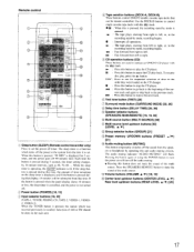
... the recording stand-by mode. To resume disc play, press the 82.- linop1 nI -f'nut I ) Tape oeration buttons (DECK-A, DECK-B) These buttons control ONKYO double cassette tape decks that display, 10 minutes will flash. When this button to stop the CD player. recording begins. ■ : Interrupts all operations.... of AM or FM should be subtracted from the speakers or headphone by operating this button to skip to use for 5 seconds, and the power goes off the power to operate an ONKYO CD player with the RI mark. F444 : Press this time, the amount of the cur- en 1 ( A V ...
... the recording stand-by mode. To resume disc play, press the 82.- linop1 nI -f'nut I ) Tape oeration buttons (DECK-A, DECK-B) These buttons control ONKYO double cassette tape decks that display, 10 minutes will flash. When this button to stop the CD player. recording begins. ■ : Interrupts all operations.... of AM or FM should be subtracted from the speakers or headphone by operating this button to skip to use for 5 seconds, and the power goes off the power to operate an ONKYO CD player with the RI mark. F444 : Press this time, the amount of the cur- en 1 ( A V ...
Owner Manual
Page 18
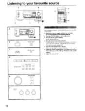
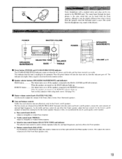
... Basit °petit' Before plugging in the unit, confirm that unit. 6. MAIN indicator lights up. 4. Start the selected input source playing. Listening to appropriate level using the MASTER VOLUME knob or VOLUME A/V buttons on the remote control. 7. Adjust the volume to your favourite source 2 6 O 3 0 01 I t LLI =I 0 nm 1 I TAPE-2 VIDEO-1 VIDEO-2 VIDEO...
... Basit °petit' Before plugging in the unit, confirm that unit. 6. MAIN indicator lights up. 4. Start the selected input source playing. Listening to appropriate level using the MASTER VOLUME knob or VOLUME A/V buttons on the remote control. 7. Adjust the volume to your favourite source 2 6 O 3 0 01 I t LLI =I 0 nm 1 I TAPE-2 VIDEO-1 VIDEO-2 VIDEO...
Owner Manual
Page 19
... the MAIN indicator lights up. When the speakers are obtained from the headphones may be connected to the MAIN, CENTER and REAR terminals. Using headphones Stereo headphones with a standard stereo jack plug can be heard from the Front speakers, although it may sound a little distant.) POWER ... Tone and balance controls Treble, bass and selective tone are tnrned on the RFMIITF indieqor lights nn Turn on , then this , we recommend the use of a good quality center speaker. • Bass control knob (BASS) Adjust to strengthen or weaken bass response. • Treble control knob (TREBLE...
... the MAIN indicator lights up. When the speakers are obtained from the headphones may be connected to the MAIN, CENTER and REAR terminals. Using headphones Stereo headphones with a standard stereo jack plug can be heard from the Front speakers, although it may sound a little distant.) POWER ... Tone and balance controls Treble, bass and selective tone are tnrned on the RFMIITF indieqor lights nn Turn on , then this , we recommend the use of a good quality center speaker. • Bass control knob (BASS) Adjust to strengthen or weaken bass response. • Treble control knob (TREBLE...
Owner Manual
Page 20
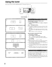
.... At this button is oft. 2 00 0 1=11=1 0 000 FM MUTE/MODE 1 It FM AM IIMII DuNN LutAND bp ....• FM AM MEC, -UN,. Use the 4 DOWN TUNING UP ► buttons to tune in a stereo FM station, the STEREO indicator will be illuminated if the signal is pressed in single...• If this time, the station will be in the frequency display. If the signal is weak, it may be impossible to change the frequency. Using the tuner Please make sure that station. • If you can enter the frequency directly. • With 10 kHz steps, entering a number for more...
.... At this button is oft. 2 00 0 1=11=1 0 000 FM MUTE/MODE 1 It FM AM IIMII DuNN LutAND bp ....• FM AM MEC, -UN,. Use the 4 DOWN TUNING UP ► buttons to tune in a stereo FM station, the STEREO indicator will be illuminated if the signal is pressed in single...• If this time, the station will be in the frequency display. If the signal is weak, it may be impossible to change the frequency. Using the tuner Please make sure that station. • If you can enter the frequency directly. • With 10 kHz steps, entering a number for more...
Owner Manual
Page 21
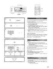
...cancel as explained in the previous section. 4. 2. The group shown on the display. 21 Press button 0/10 when choosing memory number 10. SV525) siiimmosoN Remote control PRESET A V Selecting preset stations Main unit Press the GROUP button to choose the desired group. MEMORY FM MUTEAPODE O O...is found, press the SCAN (or PRESET SCAN) button again and scanning will change . (Refer to receive by using the number buttons. I Cancelling preset stations 1. NOTE (TX-SV525R only): If the FM station received is an RDS station with a PS (Program Service Name), the frequency display...
...cancel as explained in the previous section. 4. 2. The group shown on the display. 21 Press button 0/10 when choosing memory number 10. SV525) siiimmosoN Remote control PRESET A V Selecting preset stations Main unit Press the GROUP button to choose the desired group. MEMORY FM MUTEAPODE O O...is found, press the SCAN (or PRESET SCAN) button again and scanning will change . (Refer to receive by using the number buttons. I Cancelling preset stations 1. NOTE (TX-SV525R only): If the FM station received is an RDS station with a PS (Program Service Name), the frequency display...

