Owner Manual
Page 1
Remote controller 63 Appendix 76 Please retain this manual for purchasing the Onkyo AV Receiver. Following the instructions in this manual thoroughly before making connections and plugging in the unit. Please read this manual will enable you for future reference. Contents AV Receiver TX-SR700/700E TX-SR600/600E Instruction Manual Before using 2 Facilities and connections 8 Setup and operation 36 Thank you to obtain optimum performance and listening enjoyment from your new AV Receiver.
Remote controller 63 Appendix 76 Please retain this manual for purchasing the Onkyo AV Receiver. Following the instructions in this manual thoroughly before making connections and plugging in the unit. Please read this manual will enable you for future reference. Contents AV Receiver TX-SR700/700E TX-SR600/600E Instruction Manual Before using 2 Facilities and connections 8 Setup and operation 36 Thank you to obtain optimum performance and listening enjoyment from your new AV Receiver.
Owner Manual
Page 4
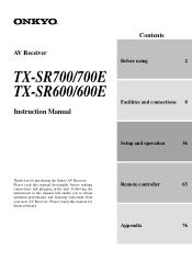
... 23 When using the ZONE 2 PRE OUT terminals 23 AC OUTLETS 29 REMOTE CONTROL 29 Connections (TX-SR600/600E 24 Connecting your audio components 24 Connecting your video components 25 AC OUTLETS 29 REMOTE CONTROL 29 Connecting speakers 30 Standard speaker setup for surround sound 30 Minimum ...the speaker cable 31 Connecting a subwoofer 31 Connecting to the SPEAKERS B terminals (TX-SR600/600E only 31 Connecting the power 33 Turning on the power 33 Turning on the power from the remote controller ........ 33 Connecting antennas 34 Assembling the AM loop antenna 34 Connecting the...
... 23 When using the ZONE 2 PRE OUT terminals 23 AC OUTLETS 29 REMOTE CONTROL 29 Connections (TX-SR600/600E 24 Connecting your audio components 24 Connecting your video components 25 AC OUTLETS 29 REMOTE CONTROL 29 Connecting speakers 30 Standard speaker setup for surround sound 30 Minimum ...the speaker cable 31 Connecting a subwoofer 31 Connecting to the SPEAKERS B terminals (TX-SR600/600E only 31 Connecting the power 33 Turning on the power 33 Turning on the power from the remote controller ........ 33 Connecting antennas 34 Assembling the AM loop antenna 34 Connecting the...
Owner Manual
Page 5
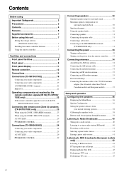
...your programmed remote controller 69 DVD MODE (DVD Player Mode 69 VCR MODE (VCR Mode 69 TV MODE (TV Mode 69 Programming the commands of the messages shown below appears 78 Specifications (TX-SR700/700E 79 Specifications (TX-SR600/600E) ....... MORI ONKYO EUROPE ...ELECTRONICS GmbH 5 back cover Declaration of Conformity We, ONKYO EUROPE ELECTRONICS GmbH INDUSTRIESTRASSE 20 82110 GERMERING, GERMANY declare in own responsibility...
...your programmed remote controller 69 DVD MODE (DVD Player Mode 69 VCR MODE (VCR Mode 69 TV MODE (TV Mode 69 Programming the commands of the messages shown below appears 78 Specifications (TX-SR700/700E 79 Specifications (TX-SR600/600E) ....... MORI ONKYO EUROPE ...ELECTRONICS GmbH 5 back cover Declaration of Conformity We, ONKYO EUROPE ELECTRONICS GmbH INDUSTRIESTRASSE 20 82110 GERMERING, GERMANY declare in own responsibility...
Owner Manual
Page 6
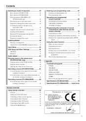
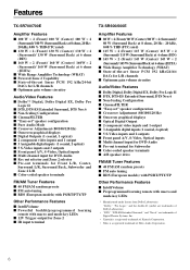
...FM/AM random presets I FM auto tuning I RDS (European models) with PS/RT/PTY/TP Other Performance Features I IntelliVolume I Preprogrammed learning remote with macro and mode-key LEDs I 12V Trigger output for Front L/R, Center, Surround L/R, Surround Back, Subwoofer and Zone 2 L/R I Color... Front panel A/V, S-Video, Optical inputs I Multi channel input for DVD-Audio I Rec out selector and Zone 2 selector I Pre-out terminals for Zone 2 I IR input terminal TX-SR600/600E Amplifier Features I 80 W × 2 (Front)/ 80 W (Center)/ 80 W × 2 (Surround)/ 80 W (Surround Back) at 8 ohms, 20 Hz - ...
...FM/AM random presets I FM auto tuning I RDS (European models) with PS/RT/PTY/TP Other Performance Features I IntelliVolume I Preprogrammed learning remote with macro and mode-key LEDs I 12V Trigger output for Front L/R, Center, Surround L/R, Surround Back, Subwoofer and Zone 2 L/R I Color... Front panel A/V, S-Video, Optical inputs I Multi channel input for DVD-Audio I Rec out selector and Zone 2 selector I Pre-out terminals for Zone 2 I IR input terminal TX-SR600/600E Amplifier Features I 80 W × 2 (Front)/ 80 W (Center)/ 80 W × 2 (Surround)/ 80 W (Surround Back) at 8 ohms, 20 Hz - ...
Owner Manual
Page 7
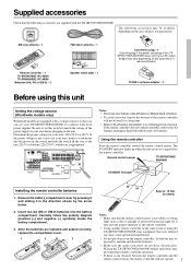
... Its buttons may be used for your area before plugging in the unit. Be sure to set your TX-SR700/700E/600/600E to avoid damage from the remote controller. If the preset voltage is not correct for it in the same room or using this unit Setting...from corrosion. Carefully follow the polarity diagram (positive (+) and negative (-) symbols) inside the battery compartment. 3. AM loop antenna × 1 RC-482M Remote controller × 1 TX-SR700/700E: RC-482M TX-SR600/600E: RC-480M Batteries (AA, R6 or UM-3) × 2 Front Left Front Left SP-B / Zone 2 Left SP-B / Zone 2 ...
... Its buttons may be used for your area before plugging in the unit. Be sure to set your TX-SR700/700E/600/600E to avoid damage from the remote controller. If the preset voltage is not correct for it in the same room or using this unit Setting...from corrosion. Carefully follow the polarity diagram (positive (+) and negative (-) symbols) inside the battery compartment. 3. AM loop antenna × 1 RC-482M Remote controller × 1 TX-SR700/700E: RC-482M TX-SR600/600E: RC-480M Batteries (AA, R6 or UM-3) × 2 Front Left Front Left SP-B / Zone 2 Left SP-B / Zone 2 ...
Owner Manual
Page 9
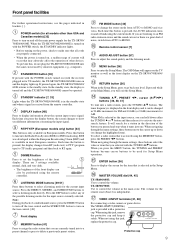
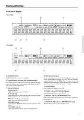
...back to activate the autosearch feature. Remote control sensor [7] AUDIO ADJUST button [57] Press to delete a previously preset station. When you are 3 settings available: normal, dark, and very dark. • The brightness of the front display. MASTER VOLUME dial [44, 45] TX-SR600/600E: Use to be performed using ...this , do not plug the TX-SR700/700E/600/600E into to a preset channel or press to adjust the sound quality and the listening mode....
...back to activate the autosearch feature. Remote control sensor [7] AUDIO ADJUST button [57] Press to delete a previously preset station. When you are 3 settings available: normal, dark, and very dark. • The brightness of the front display. MASTER VOLUME dial [44, 45] TX-SR600/600E: Use to be performed using ...this , do not plug the TX-SR700/700E/600/600E into to a preset channel or press to adjust the sound quality and the listening mode....
Owner Manual
Page 10
... the currently selected input source for recording or outputting to the remote zone is referred to as that selected for the main zone will be used to select the input source for recording (Rec Out). SPEAKERS A/B buttons (TX-SR600/600E only) [45] Press these buttons to select the input... displayed, then the same input source as the remote zone (Zone 2). Front panel facilities Input source buttons (DVD, VIDEO 1-4, TAPE, TUNER, PHONO (TX-SR700/700E only), and CD) [44, 45, 53] TX-SR600/600E: These buttons are used at the same time. TX-SR700/700E: Press these buttons to ZONE 2. ...
... the currently selected input source for recording or outputting to the remote zone is referred to as that selected for the main zone will be used to select the input source for recording (Rec Out). SPEAKERS A/B buttons (TX-SR600/600E only) [45] Press these buttons to select the input... displayed, then the same input source as the remote zone (Zone 2). Front panel facilities Input source buttons (DVD, VIDEO 1-4, TAPE, TUNER, PHONO (TX-SR700/700E only), and CD) [44, 45, 53] TX-SR600/600E: These buttons are used at the same time. TX-SR700/700E: Press these buttons to ZONE 2. ...
Owner Manual
Page 11
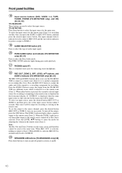
...During normal operation, shows the current input source and volume. SLEEP indicator Lights when the sleep timer is received. REC OUT indicator (TX-SR700/700E only) Lights when recording the input source from one of the listening mode indicators lights to another (Rec Out). RDS...indicator Lights when receiving FM broadcasts in use. 11 SPEAKERS A/B indicators (TX-SR600/600E only) Indicates which speaker system is selected, shows the frequency and preset number. ZONE 2 indicator (TX-SR700/700E only) Lights when using the remote zone (Zone 2). When the FM or AM input is currently in ...
...During normal operation, shows the current input source and volume. SLEEP indicator Lights when the sleep timer is received. REC OUT indicator (TX-SR700/700E only) Lights when recording the input source from one of the listening mode indicators lights to another (Rec Out). RDS...indicator Lights when receiving FM broadcasts in use. 11 SPEAKERS A/B indicators (TX-SR600/600E only) Indicates which speaker system is selected, shows the frequency and preset number. ZONE 2 indicator (TX-SR700/700E only) Lights when using the remote zone (Zone 2). When the FM or AM input is currently in ...
Owner Manual
Page 12
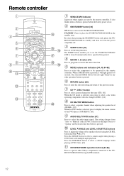
...] Press to turn the power completely off automatically after a specified time period. When a MODE button is pressed, it will also light whenever any other Onkyo components connected to the TXSR700/700E/600/600E using the CH SEL button (LEVEL / ). [39] Press the ANGLE button to select a camera angle when...is selected as the input source) to place the TX-SR700/700E/600/600E in standby and does not turn on the TX-SR700/700E/600/600E. SLEEP button [47] Press to set the TX-SR700/700E/600/ 600E to be operated by the remote controller. MODE buttons and indicators [44, 45, ...
...] Press to turn the power completely off automatically after a specified time period. When a MODE button is pressed, it will also light whenever any other Onkyo components connected to the TXSR700/700E/600/600E using the CH SEL button (LEVEL / ). [39] Press the ANGLE button to select a camera angle when...is selected as the input source) to place the TX-SR700/700E/600/600E in standby and does not turn on the TX-SR700/700E/600/600E. SLEEP button [47] Press to set the TX-SR700/700E/600/ 600E to be operated by the remote controller. MODE buttons and indicators [44, 45, ...
Owner Manual
Page 13
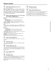
...function on the remote zone (ZONE 2) (not used with the TX-SR700/700E. TEST/MENU button This button is selected, press to find the specific section on a DVD where you can select a listening mode. [51] Note: During playback of a track. [64-66] PURE A: TX-SR600/600E: Not used with the TX-SR600/600E. The input... to perform operations on or off the lights in the MD mode, press to turn on the front panel of the remote controller. Use this button in conjunction with the TX-SR600/600E). [60] When in the buttons of the TXSR700/700E/600/600E. DVD:DVD, CD:CD, V1:VIDEO1, V2:VIDEO2,...
...function on the remote zone (ZONE 2) (not used with the TX-SR700/700E. TEST/MENU button This button is selected, press to find the specific section on a DVD where you can select a listening mode. [51] Note: During playback of a track. [64-66] PURE A: TX-SR600/600E: Not used with the TX-SR600/600E. The input... to perform operations on or off the lights in the MD mode, press to turn on the front panel of the remote controller. Use this button in conjunction with the TX-SR600/600E). [60] When in the buttons of the TXSR700/700E/600/600E. DVD:DVD, CD:CD, V1:VIDEO1, V2:VIDEO2,...
Owner Manual
Page 15
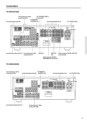
... When using the ZONE 2 SPEAKERS terminals [23] TX-SR600/600E Connecting your video components [25] 15 TX-SR600E AC OUTLETS AC 230-240V 50 Hz SWITCHED TOTAL 100W MAX. Connecting a subwoofer [31] Connecting your audio components [24] REMOTE Connecting antennas [34] CONTROL [27] Connecting speakers ... SURROUND BACK AC OUTLETS AC 230-240V 50 Hz SWITCHED TOTAL 100W MAX. Connections TX-SR700/700E Connecting your audio components [16] 12V TRIGGER ZONE 2 terminal [21] Connecting antennas [34] REMOTE CONTROL [27] Connecting speakers [31] AC OUTLETS [26] ANTENNA FM AM 75 GND R...
... When using the ZONE 2 SPEAKERS terminals [23] TX-SR600/600E Connecting your video components [25] 15 TX-SR600E AC OUTLETS AC 230-240V 50 Hz SWITCHED TOTAL 100W MAX. Connecting a subwoofer [31] Connecting your audio components [24] REMOTE Connecting antennas [34] CONTROL [27] Connecting speakers ... SURROUND BACK AC OUTLETS AC 230-240V 50 Hz SWITCHED TOTAL 100W MAX. Connections TX-SR700/700E Connecting your audio components [16] 12V TRIGGER ZONE 2 terminal [21] Connecting antennas [34] REMOTE CONTROL [27] Connecting speakers [31] AC OUTLETS [26] ANTENNA FM AM 75 GND R...
Owner Manual
Page 17
... COMPONENT VIDEO INPUT 2 INPUT 1 OUTPUT Y PB DIGITAL INPUT OPTICAL 2 1 DIGITAL VIDEO 3 OUTPUT COAXIAL IN OPTICAL VIDEO 2 OUT IN VIDEO 1 OUT IN REMOTE CONTROL PR DVD IN MONITOR OUT V ZONE 2 12 V TRIGGE OUT SUBWOOFER PRE OUT IN L R CD COAXIAL DIGITAL INPUT OUT IN IN OUT IN TAPE... output from the component video connectors. • For more information about the DIGITAL INPUT/OUTPUT jacks, see page 16. 17 Connections (TX-SR700/700E) Connecting a DVD Player with incredibly lifelike colors and crisp detail. • The signal that comes in from COMPONENT VIDEO INPUT...
... COMPONENT VIDEO INPUT 2 INPUT 1 OUTPUT Y PB DIGITAL INPUT OPTICAL 2 1 DIGITAL VIDEO 3 OUTPUT COAXIAL IN OPTICAL VIDEO 2 OUT IN VIDEO 1 OUT IN REMOTE CONTROL PR DVD IN MONITOR OUT V ZONE 2 12 V TRIGGE OUT SUBWOOFER PRE OUT IN L R CD COAXIAL DIGITAL INPUT OUT IN IN OUT IN TAPE... output from the component video connectors. • For more information about the DIGITAL INPUT/OUTPUT jacks, see page 16. 17 Connections (TX-SR700/700E) Connecting a DVD Player with incredibly lifelike colors and crisp detail. • The signal that comes in from COMPONENT VIDEO INPUT...

Owner Manual
Page 18
... COMPONENT VIDEO INPUT 2 INPUT 1 OUTPUT Y DIGITAL INPUT OPTICAL 2 1 DIGITAL VIDEO 3 OUTPUT COAXIAL IN OPTICAL VIDEO 2 OUT IN VIDEO 1 OUT IN PB REMOTE PR CONTROL DVD IN MONITOR OUT V ZONE 2 12 V TRIGGE OUT SUBWOOFER PRE OUT IN L R CD COAXIAL DIGITAL INPUT OUT IN IN OUT IN TAPE ...TXSR700/700E. If the device has a 5.1-channel output, connect the DVD FRONT L/ R, SURR L/R, CENTER, and SUBWOOFER (5.1-channel input) jacks of the TX-SR700/700E to the COMPONENT VIDEO INPUT 2 jacks, this must be changed at "Input Setup" → "Digital Input" (see page 54). Using an...
... COMPONENT VIDEO INPUT 2 INPUT 1 OUTPUT Y DIGITAL INPUT OPTICAL 2 1 DIGITAL VIDEO 3 OUTPUT COAXIAL IN OPTICAL VIDEO 2 OUT IN VIDEO 1 OUT IN PB REMOTE PR CONTROL DVD IN MONITOR OUT V ZONE 2 12 V TRIGGE OUT SUBWOOFER PRE OUT IN L R CD COAXIAL DIGITAL INPUT OUT IN IN OUT IN TAPE ...TXSR700/700E. If the device has a 5.1-channel output, connect the DVD FRONT L/ R, SURR L/R, CENTER, and SUBWOOFER (5.1-channel input) jacks of the TX-SR700/700E to the COMPONENT VIDEO INPUT 2 jacks, this must be changed at "Input Setup" → "Digital Input" (see page 54). Using an...
Owner Manual
Page 19
...Video output L (white) Analog audio output R (red) ANTENNA FM AM 75 R L PHONO IN GND COMPONENT VIDEO INPUT 2 INPUT 1 OUTPUT Y PB REMOT PR CONTRO DIGITAL INPUT OPTICAL 2 1 DIGITAL VIDEO 3 OUTPUT COAXIAL IN OPTICAL VIDEO 2 OUT IN VIDEO 1 OUT IN DVD MONITOR IN OUT ZONE V ...FRONT SURR CENTER L VIDEO 1 R DVD SUB WOOFER Y PB Component video output PR Video output S video output 5. With the initial settings of the TX-SR700/700E, the VIDEO 3 input source is made at a different jack, this must be changed at "Input Setup" → "Digital Input" (see...
...Video output L (white) Analog audio output R (red) ANTENNA FM AM 75 R L PHONO IN GND COMPONENT VIDEO INPUT 2 INPUT 1 OUTPUT Y PB REMOT PR CONTRO DIGITAL INPUT OPTICAL 2 1 DIGITAL VIDEO 3 OUTPUT COAXIAL IN OPTICAL VIDEO 2 OUT IN VIDEO 1 OUT IN DVD MONITOR IN OUT ZONE V ...FRONT SURR CENTER L VIDEO 1 R DVD SUB WOOFER Y PB Component video output PR Video output S video output 5. With the initial settings of the TX-SR700/700E, the VIDEO 3 input source is made at a different jack, this must be changed at "Input Setup" → "Digital Input" (see...
Owner Manual
Page 20
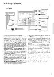
...DVD recorder or other digital video recording device (VIDEO 2) ANTENNA FM AM 75 R L PHONO IN GND COMPONENT VIDEO INPUT 2 INPUT 1 OUTPUT Y PB REMOT CONTRO PR DIGITAL INPUT OPTICAL 2 1 DIGITAL VIDEO 3 OUTPUT COAXIAL IN OPTICAL VIDEO 2 OUT IN VIDEO 1 OUT IN DVD MONITOR IN OUT ZONE V ... digital input, connect it to either the DIGITAL INPUT COAXIAL jack or the DIGITAL INPUT OPTICAL jack of the TX-SR700/700E depending on the TX-SR700/ 700E. Connections (TX-SR700/700E) Video output S Video output Video input S Video input 7. Using RCA audio cables, connect the ...
...DVD recorder or other digital video recording device (VIDEO 2) ANTENNA FM AM 75 R L PHONO IN GND COMPONENT VIDEO INPUT 2 INPUT 1 OUTPUT Y PB REMOT CONTRO PR DIGITAL INPUT OPTICAL 2 1 DIGITAL VIDEO 3 OUTPUT COAXIAL IN OPTICAL VIDEO 2 OUT IN VIDEO 1 OUT IN DVD MONITOR IN OUT ZONE V ... digital input, connect it to either the DIGITAL INPUT COAXIAL jack or the DIGITAL INPUT OPTICAL jack of the TX-SR700/700E depending on the TX-SR700/ 700E. Connections (TX-SR700/700E) Video output S Video output Video input S Video input 7. Using RCA audio cables, connect the ...
Owner Manual
Page 21
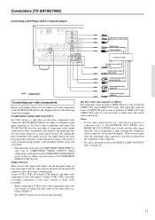
...TX-SR700/700E alone. TX-SR700E SURROUND BACK AC OUTLETS AC 230-240V 50 Hz SWITCHED TOTAL 100W MAX. Center speaker 21 ANTENNA FM AM 75 GND R L PHONO IN COMPONENT VIDEO INPUT 2 INPUT 1 OUTPUT Y L PB DIGITAL INPUT OPTICAL 2 1 DIGITAL VIDEO 3 OUTPUT COAXIAL IN OPTICAL VIDEO 2 OUT IN VIDEO 1 OUT IN REMOTE... R R AV RECEIVER MODEL NO. If the device has an optical digital output, connect it to the VIDEO 4 VIDEO jack of the TX-SR700/700E. Front right speaker 3. Front left speaker 6. Connecting video camera, etc. (VIDEO 4 INPUT) Using an RCA video cable, ...
...TX-SR700/700E alone. TX-SR700E SURROUND BACK AC OUTLETS AC 230-240V 50 Hz SWITCHED TOTAL 100W MAX. Center speaker 21 ANTENNA FM AM 75 GND R L PHONO IN COMPONENT VIDEO INPUT 2 INPUT 1 OUTPUT Y L PB DIGITAL INPUT OPTICAL 2 1 DIGITAL VIDEO 3 OUTPUT COAXIAL IN OPTICAL VIDEO 2 OUT IN VIDEO 1 OUT IN REMOTE... R R AV RECEIVER MODEL NO. If the device has an optical digital output, connect it to the VIDEO 4 VIDEO jack of the TX-SR700/700E. Front right speaker 3. Front left speaker 6. Connecting video camera, etc. (VIDEO 4 INPUT) Using an RCA video cable, ...
Owner Manual
Page 22
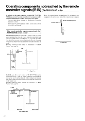
Make the connections as those given below: • Onkyo's Multi-Room System kit (IR Remote Controller Extension System) • Multiroom A/V distribution and control system such as shown below shows how to make the proper connections for the remote zone. With this connection, select "Main" at "Preference" → "IR IN... kit (sold separately) such as one of those from Niles® and Xantech® If the remote controller signal does not reach the TX-SR700/700E remote sensor If the TX-SR700/700E is located inside a cabinet or other side of the cabinet where the infrared rays from ...
Make the connections as those given below: • Onkyo's Multi-Room System kit (IR Remote Controller Extension System) • Multiroom A/V distribution and control system such as shown below shows how to make the proper connections for the remote zone. With this connection, select "Main" at "Preference" → "IR IN... kit (sold separately) such as one of those from Niles® and Xantech® If the remote controller signal does not reach the TX-SR700/700E remote sensor If the TX-SR700/700E is located inside a cabinet or other side of the cabinet where the infrared rays from ...
Owner Manual
Page 23
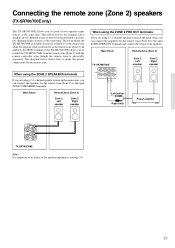
..., you can connect the amplifier for the remote zone (Zone 2) to the open ZONE 2 SPEAKERS terminals. Connecting the remote zone (Zone 2) speakers (TX-SR700/700E only) The TX-SR700/700E allows you to control the TX-SR700/700E from the remote zone (Zone 2) with the remote controller even though the remote zone is physically separated. In addition, the...
..., you can connect the amplifier for the remote zone (Zone 2) to the open ZONE 2 SPEAKERS terminals. Connecting the remote zone (Zone 2) speakers (TX-SR700/700E only) The TX-SR700/700E allows you to control the TX-SR700/700E from the remote zone (Zone 2) with the remote controller even though the remote zone is physically separated. In addition, the...
Owner Manual
Page 25
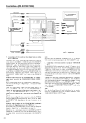
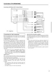
... (surround L/R) R (red) L (white) Analog audio output (front L/R) R (red) Digital audio output (coaxial) Connecting your video components to the TX-SR600/600E. Refer to the diagram above for direct component video input. The result is vastly increased image quality, with 5.1-Channel Output ANTENNA FM AM 75... 2 1 DIGITAL DIGITAL OUTPUT INPUT OPTICAL COAXIAL COMPONENT VIDEO INPUT 2 INPUT 1 OUTPUT Y VIDEO 3 VIDEO 2 VIDEO 1 IN IN OUT IN PB REMOTE CONTROL PR DVD MONITOR IN OUT VIDEO CD IN L SUBWOOFER PRE OUT R TAPE OUT IN S VIDEO IN IN OUT IN FRONT SURR CENTER L ...
... (surround L/R) R (red) L (white) Analog audio output (front L/R) R (red) Digital audio output (coaxial) Connecting your video components to the TX-SR600/600E. Refer to the diagram above for direct component video input. The result is vastly increased image quality, with 5.1-Channel Output ANTENNA FM AM 75... 2 1 DIGITAL DIGITAL OUTPUT INPUT OPTICAL COAXIAL COMPONENT VIDEO INPUT 2 INPUT 1 OUTPUT Y VIDEO 3 VIDEO 2 VIDEO 1 IN IN OUT IN PB REMOTE CONTROL PR DVD MONITOR IN OUT VIDEO CD IN L SUBWOOFER PRE OUT R TAPE OUT IN S VIDEO IN IN OUT IN FRONT SURR CENTER L ...
Owner Manual
Page 26
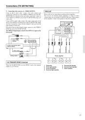
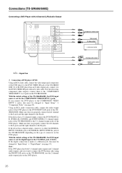
...DIGITAL INPUT OPTICAL 2 1 DIGITAL DIGITAL OUTPUT INPUT OPTICAL COAXIAL COMPONENT VIDEO INPUT 2 INPUT 1 OUTPUT Y VIDEO 3 VIDEO 2 VIDEO 1 IN IN OUT IN PB REMOTE CONTROL PR DVD MONITOR IN OUT VIDEO CD IN L SUBWOOFER PRE OUT R TAPE OUT IN S VIDEO IN IN OUT IN FRONT SURR CENTER L L R ... Using an RCA video cable, connect the video output jack (composite) of the DVD player to the DVD FRONT L/R jacks of the TX-SR600/ 600E. Connections (TX-SR600/600E) Connecting a DVD Player with an S video cable. Using an RCA audio connection cable, connect the audio output jacks of the ...
...DIGITAL INPUT OPTICAL 2 1 DIGITAL DIGITAL OUTPUT INPUT OPTICAL COAXIAL COMPONENT VIDEO INPUT 2 INPUT 1 OUTPUT Y VIDEO 3 VIDEO 2 VIDEO 1 IN IN OUT IN PB REMOTE CONTROL PR DVD MONITOR IN OUT VIDEO CD IN L SUBWOOFER PRE OUT R TAPE OUT IN S VIDEO IN IN OUT IN FRONT SURR CENTER L L R ... Using an RCA video cable, connect the video output jack (composite) of the DVD player to the DVD FRONT L/R jacks of the TX-SR600/ 600E. Connections (TX-SR600/600E) Connecting a DVD Player with an S video cable. Using an RCA audio connection cable, connect the audio output jacks of the ...


