Owner Manual
Page 1
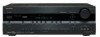
Please retain this manual for purchasing an Onkyo AV Receiver. Enjoying the Listening Modes ..... 55 Advanced Operation 62 Troubleshooting 90 En AV Receiver TX-SR506 TX-SR576 Instruction Manual Contents Introduction 2 Connection 14 Turning On & First Time Setup..... 35 Basic Operation Playing your new AV Receiver. Following the instructions in this manual thoroughly before making connections and plugging in the unit...
Please retain this manual for purchasing an Onkyo AV Receiver. Enjoying the Listening Modes ..... 55 Advanced Operation 62 Troubleshooting 90 En AV Receiver TX-SR506 TX-SR576 Instruction Manual Contents Introduction 2 Connection 14 Turning On & First Time Setup..... 35 Basic Operation Playing your new AV Receiver. Following the instructions in this manual thoroughly before making connections and plugging in the unit...
Owner Manual
Page 4
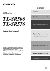
...Back Right Surround Back Right Zone 2 Right Zone 2 Right Supplied Accessories Make sure you have the same ampere rating as that the ONKYO product described in this instruction manual is in certain countries. The wire which is coloured brown must be connected to mount the AC plug...the product name indicates the color. For European Models Declaration of Conformity We, ONKYO EUROPE ELECTRONICS GmbH LIEGNITZERSTRASSE 6, 82194 GROEBENZELL, GERMANY declare in your AC outlet does not match with the plug on the AV receiver's power cord. (Adapter varies from country to country.) *How to the...
...Back Right Surround Back Right Zone 2 Right Zone 2 Right Supplied Accessories Make sure you have the same ampere rating as that the ONKYO product described in this instruction manual is in certain countries. The wire which is coloured brown must be connected to mount the AC plug...the product name indicates the color. For European Models Declaration of Conformity We, ONKYO EUROPE ELECTRONICS GmbH LIEGNITZERSTRASSE 6, 82194 GROEBENZELL, GERMANY declare in your AC outlet does not match with the plug on the AV receiver's power cord. (Adapter varies from country to country.) *How to the...
Owner Manual
Page 5
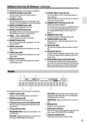
...Turntable 31 Connecting a Cassette, CDR, MiniDisc, or DAT Recorder 32 Connecting an RI Dock 33 Connecting Onkyo Components 34 Connecting the Power Cord 34 Turning On the AV Receiver 35 Turning On and Standby 35 First Time Setup 36 Automatic Speaker Setup (Audyssey 2EQ) ..........36 ...42 Changing the Input Display 43 Automatic Audio Input Selection Setup (TX-SR576 only 44 Playing Your AV Components 45 Basic AV Receiver Operation 45 Common Functions 46 Setting the Display Brightness 46 Muting the AV Receiver 46 Using the Sleep Timer 46 Using Headphones 47 Displaying Source ...
...Turntable 31 Connecting a Cassette, CDR, MiniDisc, or DAT Recorder 32 Connecting an RI Dock 33 Connecting Onkyo Components 34 Connecting the Power Cord 34 Turning On the AV Receiver 35 Turning On and Standby 35 First Time Setup 36 Automatic Speaker Setup (Audyssey 2EQ) ..........36 ...42 Changing the Input Display 43 Automatic Audio Input Selection Setup (TX-SR576 only 44 Playing Your AV Components 45 Basic AV Receiver Operation 45 Common Functions 46 Setting the Display Brightness 46 Muting the AV Receiver 46 Using the Sleep Timer 46 Using Headphones 47 Displaying Source ...
Owner Manual
Page 7
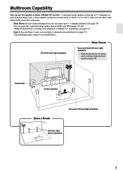
... listening modes such as we call it. Subwoofer Center speaker Zone 2 Room Surround left and right speakers * While Powered Zone 2 is being used with this AV receiver-a surround-sound speaker system (up to 5.1-channels (see page 14). Main Room: In your main listening room, you can enjoy up to 7.1 channels) in a second...
... listening modes such as we call it. Subwoofer Center speaker Zone 2 Room Surround left and right speakers * While Powered Zone 2 is being used with this AV receiver-a surround-sound speaker system (up to 5.1-channels (see page 14). Main Room: In your main listening room, you can enjoy up to 7.1 channels) in a second...

Owner Manual
Page 8
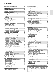
A ON/STANDBY button (35) F Display Sets the AV receiver to Know the AV Receiver Front Panel North American model 1 23 4 5 6 ON/STANDBY STANDBY ... On or Standby. D Input selector buttons (45) Opens and closes the setup menus. Lights up when the AV receiver is on it. See "Display" on . H TUNING, PRESET, Arrow, and ENTER buttons When AM or...SETUP button Lights up when Zone 2 is selected, the TUNING [ ] [ ] buttons are used for clarity. Receives control signals from the remote controller. as arrow buttons and are used to select radio presets (see page 52). ...
A ON/STANDBY button (35) F Display Sets the AV receiver to Know the AV Receiver Front Panel North American model 1 23 4 5 6 ON/STANDBY STANDBY ... On or Standby. D Input selector buttons (45) Opens and closes the setup menus. Lights up when the AV receiver is on it. See "Display" on . H TUNING, PRESET, Arrow, and ENTER buttons When AM or...SETUP button Lights up when Zone 2 is selected, the TUNING [ ] [ ] buttons are used for clarity. Receives control signals from the remote controller. as arrow buttons and are used to select radio presets (see page 52). ...
Owner Manual
Page 9
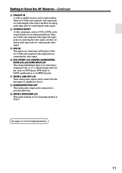
... about the currently selected input source. S DIGITAL INPUT button (42, 44) On the TX-SR506, used when setting Zone 2. Pressing this mode is selected for use with music. ...area Displays various information. 6 Audio input indicators Indicate the type of the AV receiver to input selectors. Getting to Know the AV Receiver-Continued For detailed information, see the pages in parentheses. M ZONE 2 and... Lights up when the Sleep function has been set. 2 MUTING indicator (46) Flashes while the AV receiver is the RT/PTY/TP button, and it's used to turn off . W SETUP MIC ...
... about the currently selected input source. S DIGITAL INPUT button (42, 44) On the TX-SR506, used when setting Zone 2. Pressing this mode is selected for use with music. ...area Displays various information. 6 Audio input indicators Indicate the type of the AV receiver to input selectors. Getting to Know the AV Receiver-Continued For detailed information, see the pages in parentheses. M ZONE 2 and... Lights up when the Sleep function has been set. 2 MUTING indicator (46) Flashes while the AV receiver is the RT/PTY/TP button, and it's used to turn off . W SETUP MIC ...

Owner Manual
Page 10
... FM jack is for connecting components with an analog audio input and output, such as a CD player or DVD player. Getting to Know the AV Receiver-Continued Rear Panel 12 3 4 5 67 8 9 Only some models) This voltage selector provides compatibility with front speakers and surround back speakers, ... BACK L/R terminal posts can assign each one to an input selector to suit your setup. See "Digital Input Setup" on another -capable Onkyo component for connecting the front speakers, center, surround, and surround back speakers. D COMPONENT VIDEO OUT This RCA component video output is for...
... FM jack is for connecting components with an analog audio input and output, such as a CD player or DVD player. Getting to Know the AV Receiver-Continued Rear Panel 12 3 4 5 67 8 9 Only some models) This voltage selector provides compatibility with front speakers and surround back speakers, ... BACK L/R terminal posts can assign each one to an input selector to suit your setup. See "Digital Input Setup" on another -capable Onkyo component for connecting the front speakers, center, surround, and surround back speakers. D COMPONENT VIDEO OUT This RCA component video output is for...
Owner Manual
Page 11
... jacks for connecting the video signal, and there are analog audio input jacks for connecting the audio signal. Getting to Know the AV Receiver-Continued M CBL/SAT IN A cable or satellite receiver can be connected here for recording and playback. S ZONE 2 SPEAKERS L/R These push terminals are S-Video and composite video input jacks for...
... jacks for connecting the video signal, and there are analog audio input jacks for connecting the audio signal. Getting to Know the AV Receiver-Continued M CBL/SAT IN A cable or satellite receiver can be connected here for recording and playback. S ZONE 2 SPEAKERS L/R These push terminals are S-Video and composite video input jacks for...

Owner Manual
Page 12
...Receiver mode (see page 88). E SETUP button Used to change settings. K RETURN button Returns to select AM and FM radio stations directly. 3 D.TUN button (51) Selects the Direct tuning mode. 4 DISPLAY button (51) Displays information about the current input source. You can also be controlled in parentheses. Note: • An Onkyo...]/[ ] button (45) Adjusts the volume of the AV receiver regardless of the currently selected remote controller mode. Remote Controller Controlling the AV Receiver To control the AV receiver, press the [RECEIVER] REMOTE MODE button to On or Standby. See page ...
...Receiver mode (see page 88). E SETUP button Used to change settings. K RETURN button Returns to select AM and FM radio stations directly. 3 D.TUN button (51) Selects the Direct tuning mode. 4 DISPLAY button (51) Displays information about the current input source. You can also be controlled in parentheses. Note: • An Onkyo...]/[ ] button (45) Adjusts the volume of the AV receiver regardless of the currently selected remote controller mode. Remote Controller Controlling the AV Receiver To control the AV receiver, press the [RECEIVER] REMOTE MODE button to On or Standby. See page ...
Owner Manual
Page 13
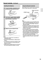
... remote controller will not work reliably if the AV receiver is installed in a rack behind colored glass doors. STANDBY indicator Remote control sensor AV receiver 2 Insert the two supplied batteries (AA/R6) in the same room, or the AV receiver is installed close to equipment that uses infrared ... diagram inside the battery compartment. 3 Replace the cover and push it and the AV receiver's remote control sensor. 13 Notes: • If the remote controller doesn't work reliably if the AV receiver is subjected to prevent damage from leakage or corrosion. • Expired batteries should ...
... remote controller will not work reliably if the AV receiver is installed in a rack behind colored glass doors. STANDBY indicator Remote control sensor AV receiver 2 Insert the two supplied batteries (AA/R6) in the same room, or the AV receiver is installed close to equipment that uses infrared ... diagram inside the battery compartment. 3 Replace the cover and push it and the AV receiver's remote control sensor. 13 Notes: • If the remote controller doesn't work reliably if the AV receiver is subjected to prevent damage from leakage or corrosion. • Expired batteries should ...
Owner Manual
Page 14
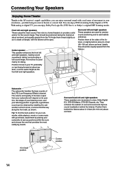
... a front corner, or at the apex. You can enjoy Dolby Pro Logic IIx, DTS Neo:6, or Onkyo's original DSP listening modes. Surround left and right speakers. Connecting Your Speakers Enjoying Home Theater Thanks to the AV receiver's superb capabilities, you can enjoy DVDs featuring Dolby Digital or DTS. Their role in a movie theater...
... a front corner, or at the apex. You can enjoy Dolby Pro Logic IIx, DTS Neo:6, or Onkyo's original DSP listening modes. Surround left and right speakers. Connecting Your Speakers Enjoying Home Theater Thanks to the AV receiver's superb capabilities, you can enjoy DVDs featuring Dolby Digital or DTS. Their role in a movie theater...

Owner Manual
Page 15
...Dipole speakers TV/screen 1 2 3 4 Normal speakers TV/screen 1 2 3 4 Connecting a Powered Subwoofer Using a suitable cable, connect the AV receiver's PRE OUT: SUBWOOFER to the input on them to do this automatically (see page 36) or manually (see page 67). Subwoofer 2. The surround...L L WOOFER R R R R CBL/SAT VCR/DVR SUB WOOFER DVD LINE INPUT PRE OUT SUB WOOFER Attaching the Speaker Labels The AV receiver's positive (+) speaker terminals are all red. (The negative (-) speaker terminals are all black.) Speaker Front left Front right Center Surround left...
...Dipole speakers TV/screen 1 2 3 4 Normal speakers TV/screen 1 2 3 4 Connecting a Powered Subwoofer Using a suitable cable, connect the AV receiver's PRE OUT: SUBWOOFER to the input on them to do this automatically (see page 36) or manually (see page 67). Subwoofer 2. The surround...L L WOOFER R R R R CBL/SAT VCR/DVR SUB WOOFER DVD LINE INPUT PRE OUT SUB WOOFER Attaching the Speaker Labels The AV receiver's positive (+) speaker terminals are all red. (The negative (-) speaker terminals are all black.) Speaker Front left Front right Center Surround left...

Owner Manual
Page 16
...Disconnect the power cord from the ends of phase and will sound unnatural. • Unnecessarily long or very thin speaker cables may damage the AV receiver. • Don't connect more , but less than one surround back speaker, connect it to the left speaker Center speaker 16 Connecting the...and 16 ohms. If you 're using only one cable to each pair of time, the built-in amp protection circuit may damage the AV receiver. • Don't connect a speaker to only negative (-) terminals. Surround back left speaker Surround back right speaker Surround left speaker Surround ...
...Disconnect the power cord from the ends of phase and will sound unnatural. • Unnecessarily long or very thin speaker cables may damage the AV receiver. • Don't connect more , but less than one surround back speaker, connect it to the left speaker Center speaker 16 Connecting the...and 16 ohms. If you 're using only one cable to each pair of time, the built-in amp protection circuit may damage the AV receiver. • Don't connect a speaker to only negative (-) terminals. Surround back left speaker Surround back right speaker Surround left speaker Surround ...
Owner Manual
Page 17
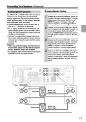
... FRONT SPEAKERS FRONT SPEAKERS L L Left speaker Woofer (low) Tweeter (high) R R Right speaker Woofer (low) Tweeter (high) 17 And connect the AV receiver's SURR BACK L negative (-) terminal to the right speaker's positive (+) woofer (low) terminal. Connecting Your Speakers-Continued Bi-amping Front Speakers The FRONT L/R...240V SURR BACK SPEAKERS Bi-AMP for front speakers, providing improved bass and treble performance. • When bi-amping is used, the AV receiver is able to drive up to 5.1 speakers in the main room. • For bi-amping, the FRONT L/R terminal posts connect to...
... FRONT SPEAKERS FRONT SPEAKERS L L Left speaker Woofer (low) Tweeter (high) R R Right speaker Woofer (low) Tweeter (high) 17 And connect the AV receiver's SURR BACK L negative (-) terminal to the right speaker's positive (+) woofer (low) terminal. Connecting Your Speakers-Continued Bi-amping Front Speakers The FRONT L/R...240V SURR BACK SPEAKERS Bi-AMP for front speakers, providing improved bass and treble performance. • When bi-amping is used, the AV receiver is able to drive up to 5.1 speakers in the main room. • For bi-amping, the FRONT L/R terminal posts connect to...
Owner Manual
Page 18
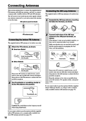
...Connect both wires of the AM antenna to connect commercially available outdoor FM and AM antennas. Push Insert wire Release AM ANTENNA Once your AV receiver, TV, speaker cables, and power cords. FM antenna jack Connecting the Indoor FM Antenna The supplied indoor FM antenna is ready for ...connected either way around). If you cannot achieve good reception with a commercially available outdoor AM antenna (see page 19). 18 Once your AV receiver is for use the tuner. Connecting Antennas This section explains how to connect the supplied indoor FM antenna and AM loop antenna, and ...
...Connect both wires of the AM antenna to connect commercially available outdoor FM and AM antennas. Push Insert wire Release AM ANTENNA Once your AV receiver, TV, speaker cables, and power cords. FM antenna jack Connecting the Indoor FM Antenna The supplied indoor FM antenna is ready for ...connected either way around). If you cannot achieve good reception with a commercially available outdoor AM antenna (see page 19). 18 Once your AV receiver is for use the tuner. Connecting Antennas This section explains how to connect the supplied indoor FM antenna and AM loop antenna, and ...
Owner Manual
Page 19
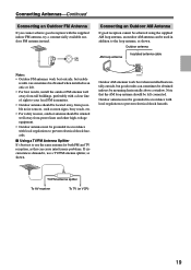
...-Continued Connecting an Outdoor FM Antenna If you cannot achieve good reception with local regulations to prevent electrical shock hazards. TV/FM antenna splitter To AV receiver To TV (or VCR) 19 Outdoor antenna must be grounded in accordance with the supplied indoor FM antenna, try a commercially available outdoor FM antenna instead...
...-Continued Connecting an Outdoor FM Antenna If you cannot achieve good reception with local regulations to prevent electrical shock hazards. TV/FM antenna splitter To AV receiver To TV (or VCR) 19 Outdoor antenna must be grounded in accordance with the supplied indoor FM antenna, try a commercially available outdoor FM antenna instead...

Owner Manual
Page 20
.... It's the most common connection format for optical. Several standard analog audio cables can carry uncompressed standard- Note: The AV receiver does not support SCART connections. 20 Use red plugs to connect composite video inputs and outputs. Right! or high-definition...and video cables away from power cords and speaker cables. Optical Digital Jacks The AV receiver's optical digital jacks have shutter-type covers that open when an optical plug is typically used on virtually all AV connections. AV Cables and Jacks • Push plugs in all the way to make good ...
.... It's the most common connection format for optical. Several standard analog audio cables can carry uncompressed standard- Note: The AV receiver does not support SCART connections. 20 Use red plugs to connect composite video inputs and outputs. Right! or high-definition...and video cables away from power cords and speaker cables. Optical Digital Jacks The AV receiver's optical digital jacks have shutter-type covers that open when an optical plug is typically used on virtually all AV connections. AV Cables and Jacks • Push plugs in all the way to make good ...
Owner Manual
Page 21
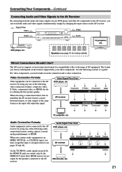
... format, bear in mind that input to an input selector (see page 16 for compatibility with a wide range of AV equipment. HDMI Multichannel Optical Coaxial Analog AV receiver On the TX-SR506, audio signals received by the HDMI IN jacks are not output by the HDMI OUT (pass thru). Connecting Your Components-Continued Connecting Audio...
... format, bear in mind that input to an input selector (see page 16 for compatibility with a wide range of AV equipment. HDMI Multichannel Optical Coaxial Analog AV receiver On the TX-SR506, audio signals received by the HDMI IN jacks are not output by the HDMI OUT (pass thru). Connecting Your Components-Continued Connecting Audio...

Owner Manual
Page 22
...Dolby Digital and DTS, use connection b or c . (To record or listen in Zone 2 as well, use its tuner to listen to the AV receiver and use a and b , or a and c .) Connection A B C a b c AV receiver COMPONENT VIDEO OUT MONITOR OUT S MONITOR OUT V CBL/SAT IN L/R DIGITAL IN COAXIAL 2 DIGITAL IN OPTICAL 1 Signal flow TV Component video... matches your TV ( a , b , or c ), and then make the connection. Step 2: Audio Connection Choose an audio connection that matches your VCR or cable or satellite receiver to TV programs through the AV receiver (see page 42) TV, projector, etc.
...Dolby Digital and DTS, use connection b or c . (To record or listen in Zone 2 as well, use its tuner to listen to the AV receiver and use a and b , or a and c .) Connection A B C a b c AV receiver COMPONENT VIDEO OUT MONITOR OUT S MONITOR OUT V CBL/SAT IN L/R DIGITAL IN COAXIAL 2 DIGITAL IN OPTICAL 1 Signal flow TV Component video... matches your TV ( a , b , or c ), and then make the connection. Step 2: Audio Connection Choose an audio connection that matches your VCR or cable or satellite receiver to TV programs through the AV receiver (see page 42) TV, projector, etc.
Owner Manual
Page 23
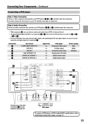
... Step 1: Video Connection Choose a video connection that matches your DVD player ( a , b , or c ), and then make the connection. Connection A B C a b c AV receiver COMPONENT VIDEO IN 1 DVD IN S DVD IN V DVD IN FRONT L/R DIGITAL IN COAXIAL 1 DIGITAL IN OPTICAL 1 Signal flow DVD player Component video output S-Video...OPTICAL OUT Y PB PR COMPONENT VIDEO OUT L R AUDIO OUT S VIDEO OUT VIDEO OUT Connect one or the other Connection c must connect the AV receiver to and record audio from a DVD or listen in Zone 2. • To enjoy Dolby Digital and DTS, use connection b or c ....
... Step 1: Video Connection Choose a video connection that matches your DVD player ( a , b , or c ), and then make the connection. Connection A B C a b c AV receiver COMPONENT VIDEO IN 1 DVD IN S DVD IN V DVD IN FRONT L/R DIGITAL IN COAXIAL 1 DIGITAL IN OPTICAL 1 Signal flow DVD player Component video output S-Video...OPTICAL OUT Y PB PR COMPONENT VIDEO OUT L R AUDIO OUT S VIDEO OUT VIDEO OUT Connect one or the other Connection c must connect the AV receiver to and record audio from a DVD or listen in Zone 2. • To enjoy Dolby Digital and DTS, use connection b or c ....


