Owner Manual
Page 2
... qualified service personnel. When the apparatus exhibits a distinct change in a fire or electric shock. Don't put candles or other apparatus (including amplifiers) that may be set 10 cm (4") away from being walked on the apparatus. Read these instructions. 3. Unplug this apparatus near any kind into the apparatus, the apparatus has been...
... qualified service personnel. When the apparatus exhibits a distinct change in a fire or electric shock. Don't put candles or other apparatus (including amplifiers) that may be set 10 cm (4") away from being walked on the apparatus. Read these instructions. 3. Unplug this apparatus near any kind into the apparatus, the apparatus has been...
Owner Manual
Page 5
...Setting the Multi Zone 135 Using Zone 2/3 136 Using the Remote Controller in Zone 2/3 and Multiroom Control Kits 138 Controlling Other Components Controlling Other Components 139 Preprogrammed Remote Control Codes 139 Looking up for Remote Control Code 139 Entering Remote Control Codes 141 Remote Control Codes for Onkyo...a Cassette Recorder 149 Activities Setup 150 Learning Commands 152 Using Normal Macros 153 Others Troubleshooting 154 Specifications (TX-NR3007 160 Specifications (TX-NR5007 161 Video Resolution Chart 162 * To reset the AV receiver to its factory defaults, turn it...
...Setting the Multi Zone 135 Using Zone 2/3 136 Using the Remote Controller in Zone 2/3 and Multiroom Control Kits 138 Controlling Other Components Controlling Other Components 139 Preprogrammed Remote Control Codes 139 Looking up for Remote Control Code 139 Entering Remote Control Codes 141 Remote Control Codes for Onkyo...a Cassette Recorder 149 Activities Setup 150 Learning Commands 152 Using Normal Macros 153 Others Troubleshooting 154 Specifications (TX-NR3007 160 Specifications (TX-NR5007 161 Video Resolution Chart 162 * To reset the AV receiver to its factory defaults, turn it...
Owner Manual
Page 8
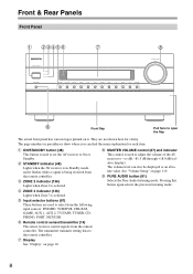
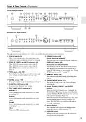
B ON/STANDBY button (48) This button is used to set the AV receiver to select from the following input sources: DVD/BD, VCR/DVR, CBL/SAT, GAME, AUX 1, AUX 2, TV/TAPE, TUNER, CD, PHONO, PORT, .../USB. D ZONE 2 indicator (136) Lights when Zone 2 is selected. F Input selector buttons (67) These buttons are not shown here for each item. The transmitter transmits setting data to open the flap The actual front panel has various logos printed on it flashes while a signal is being received from the remote controller...
B ON/STANDBY button (48) This button is used to set the AV receiver to select from the following input sources: DVD/BD, VCR/DVR, CBL/SAT, GAME, AUX 1, AUX 2, TV/TAPE, TUNER, CD, PHONO, PORT, .../USB. D ZONE 2 indicator (136) Lights when Zone 2 is selected. F Input selector buttons (67) These buttons are not shown here for each item. The transmitter transmits setting data to open the flap The actual front panel has various logos printed on it flashes while a signal is being received from the remote controller...
Owner Manual
Page 9
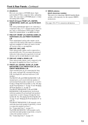
... (73) This button is also used to select the volume level of stereo headphones for Zone 2 or Zone 3. U SETUP button This button is used to set items. The [ENTER] button is used to select Zone 2. The [RT/PTY/TP] button does not work as arrow buttons and are used with music...
... (73) This button is also used to select the volume level of stereo headphones for Zone 2 or Zone 3. U SETUP button This button is used to set items. The [ENTER] button is used to select Zone 2. The [RT/PTY/TP] button does not work as arrow buttons and are used with music...

Owner Manual
Page 10
... (European and Asian models) This is used . B Speaker/channel indicators Indicate the speaker channels used . The following abbreviations indicate which speaker set to connect an HD camcorder etc. Audyssey (61, 98): Flashes during Audyssey MultEQ® XT Room Correction and Speaker Setup. E Z3 ...indicator (136) Lights when Powered Zone 3 is selected. Lights when the "Equalizer Settings" is set is selected: A or B. Front & Rear Panels-Continued W SETUP MIC jack (62) Audyssey MultEQ® XT Room Correction and Speaker Setup ...
... (European and Asian models) This is used . B Speaker/channel indicators Indicate the speaker channels used . The following abbreviations indicate which speaker set to connect an HD camcorder etc. Audyssey (61, 98): Flashes during Audyssey MultEQ® XT Room Correction and Speaker Setup. E Z3 ...indicator (136) Lights when Powered Zone 3 is selected. Lights when the "Equalizer Settings" is set is selected: A or B. Front & Rear Panels-Continued W SETUP MIC jack (62) Audyssey MultEQ® XT Room Correction and Speaker Setup ...

Owner Manual
Page 11
... 're in a cabinet. K BTL indicator (24, 26) Lights when the "Speakers Type(FrontA)" or "Speakers Type(FrontB)" setting is selected. Goes off when Manual Tuning mode is set . N USB indicator (128) Lights up when a USB mass storage device is muted. See "Digital Audio Input Setup" on ...CD and DVD/BD players. P MUTING indicator (69) Flashes while the AV receiver is detected. D DIGITAL OPTICAL IN 1 and 2 (TX-NR3007) DIGITAL OPTICAL IN 1, 2, and 3 (TX-NR5007) These optical digital audio inputs are plugged into the PHONES jack. L Headphone indicator (70) Lights when a pair of audio input...
... 're in a cabinet. K BTL indicator (24, 26) Lights when the "Speakers Type(FrontA)" or "Speakers Type(FrontB)" setting is selected. Goes off when Manual Tuning mode is set . N USB indicator (128) Lights up when a USB mass storage device is muted. See "Digital Audio Input Setup" on ...CD and DVD/BD players. P MUTING indicator (69) Flashes while the AV receiver is detected. D DIGITAL OPTICAL IN 1 and 2 (TX-NR3007) DIGITAL OPTICAL IN 1, 2, and 3 (TX-NR5007) These optical digital audio inputs are plugged into the PHONES jack. L Headphone indicator (70) Lights when a pair of audio input...
Owner Manual
Page 13
...-capable player, or an MPEG decoder. You can connect the powered subwoofer with each output. # PRE OUT: ZONE 2, ZONE 3 L/R These analog audio outputs can be set individually for each jacks respectively.
...-capable player, or an MPEG decoder. You can connect the powered subwoofer with each output. # PRE OUT: ZONE 2, ZONE 3 L/R These analog audio outputs can be set individually for each jacks respectively.
Owner Manual
Page 15
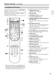
... SELECTOR buttons (67, 143 to Standby. G Arrow [R]/[X]/[F]/[S] and ENTER buttons Used to select Receiver mode. H SETUP button Used to change video settings. You can control the component corresponding to control your DVD/BD player, CD player, and other components. C ON button (48) Turns on ...the AV receiver. Remote Controller-Continued Controlling the AV Receiver To control the AV receiver, press the [RECEIVER] button to select and adjust settings. F SP LAYOUT button (70) This button is disabled. Q SLEEP button (69) Used with the AV receiver's remote controller, you ...
... SELECTOR buttons (67, 143 to Standby. G Arrow [R]/[X]/[F]/[S] and ENTER buttons Used to select Receiver mode. H SETUP button Used to change video settings. You can control the component corresponding to control your DVD/BD player, CD player, and other components. C ON button (48) Turns on ...the AV receiver. Remote Controller-Continued Controlling the AV Receiver To control the AV receiver, press the [RECEIVER] button to select and adjust settings. F SP LAYOUT button (70) This button is disabled. Q SLEEP button (69) Used with the AV receiver's remote controller, you ...

Owner Manual
Page 18
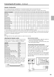
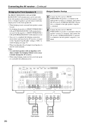
...cannot be selected at the same time. Two typical applications are bi-amped, Speakers A can drive up to 7.2 speakers. Speaker Settings Speaker Impedance Speakers Type(FrontA) Speakers Type(FrontB) Powered Zone2 Powered Zone3 6ohms Normal Normal Not Act Not Act 2-2. Speaker Configuration ...below. Speakers B FL FR FL C FR Speakers A SL SBL SR SBR ■ 5.2-channel Playback with Speakers A and Speakers B. Speaker Settings Speaker Impedance Speakers Type(FrontA) Speakers Type(FrontB) Powered Zone2 Powered Zone3 8ohms Normal BTL Not Act Not Act 2-2. For example, if front ...
...cannot be selected at the same time. Two typical applications are bi-amped, Speakers A can drive up to 7.2 speakers. Speaker Settings Speaker Impedance Speakers Type(FrontA) Speakers Type(FrontB) Powered Zone2 Powered Zone3 6ohms Normal Normal Not Act Not Act 2-2. Speaker Configuration ...below. Speakers B FL FR FL C FR Speakers A SL SBL SR SBR ■ 5.2-channel Playback with Speakers A and Speakers B. Speaker Settings Speaker Impedance Speakers Type(FrontA) Speakers Type(FrontB) Powered Zone2 Powered Zone3 8ohms Normal BTL Not Act Not Act 2-2. For example, if front ...
Owner Manual
Page 19
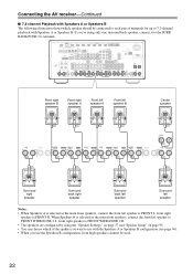
...wide right, Zone 2 right Red The supplied speaker cable labels are all red (the negative (-) speaker terminals are also color-coded and you need to set individually for a really powerful and solid bass. No matter how many speakers you 're using an external amplifier, connect the PRE OUT: SW1, SW2 to... an input on the amp. To get the best from your surround sound system, you have. You can be set the speaker settings. If your powered subwoofer, as shown. If you 're using only one subwoofer, connect it to the SURR BACK/ZONE 3 L terminal. Note: Front ...
...wide right, Zone 2 right Red The supplied speaker cable labels are all red (the negative (-) speaker terminals are also color-coded and you need to set individually for a really powerful and solid bass. No matter how many speakers you 're using an external amplifier, connect the PRE OUT: SW1, SW2 to... an input on the amp. To get the best from your surround sound system, you have. You can be set the speaker settings. If your powered subwoofer, as shown. If you 're using only one subwoofer, connect it to the SURR BACK/ZONE 3 L terminal. Note: Front ...
Owner Manual
Page 20
... speakers with an impedance of between 4 and 16 ohms. If the impedance of the two surround speakers to indicate how they should be sure to set the minimum speaker impedance to short the positive and negative wires. Front right speaker 5. If you use 4 or 5 speakers, connect each of any connections. •...
... speakers with an impedance of between 4 and 16 ohms. If the impedance of the two surround speakers to indicate how they should be sure to set the minimum speaker impedance to short the positive and negative wires. Front right speaker 5. If you use 4 or 5 speakers, connect each of any connections. •...
Owner Manual
Page 22
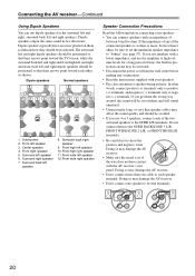
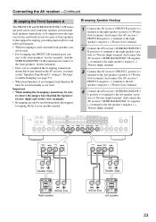
... front speakers, connect the front left speaker to FRONT L, front right speaker to FRONT WIDE/ZONE 2 R. • The speakers are configured by using the "Speaker Settings" on page 57 and "Speaker Setup" on page 95. • You can choose which speaker should be used. 22 If you use with Speakers A or...
... front speakers, connect the front left speaker to FRONT L, front right speaker to FRONT WIDE/ZONE 2 R. • The speakers are configured by using the "Speaker Settings" on page 57 and "Speaker Setup" on page 95. • You can choose which speaker should be used. 22 If you use with Speakers A or...
Owner Manual
Page 23
... front speakers' tweeter terminals. • Once you've completed the bi-amping connections shown below and turned on the AV receiver, you must set the "Speakers Type(FrontA)" setting to "Bi-Amp" to enable biamping (see page 57). • When front Speakers A are biamped, front Speakers B must be wired normally or not...
... front speakers' tweeter terminals. • Once you've completed the bi-amping connections shown below and turned on the AV receiver, you must set the "Speakers Type(FrontA)" setting to "Bi-Amp" to enable biamping (see page 57). • When front Speakers A are biamped, front Speakers B must be wired normally or not...
Owner Manual
Page 24
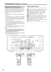
... BACK/ZONE 3 L/R terminals are not. • Once you've completed the bridging connections shown below and turned on the AV receiver, you must set the "Speakers Type(FrontA)" setting to "BTL" to the left speaker's positive (+) terminal. And connect the AV receiver's SURR BACK/ZONE 3 R positive (+) terminal to the right speaker's negative...
... BACK/ZONE 3 L/R terminals are not. • Once you've completed the bridging connections shown below and turned on the AV receiver, you must set the "Speakers Type(FrontA)" setting to "BTL" to the left speaker's positive (+) terminal. And connect the AV receiver's SURR BACK/ZONE 3 R positive (+) terminal to the right speaker's negative...

Owner Manual
Page 25
... front speakers' tweeter terminals. • Once you've completed the bi-amping connections shown below and turned on the AV receiver, you must set the "Speakers Type(FrontB)" setting to "Bi-Amp" to enable biamping (see page 57). • When front Speakers B are biamped, front Speakers A must be used. • For bi...
... front speakers' tweeter terminals. • Once you've completed the bi-amping connections shown below and turned on the AV receiver, you must set the "Speakers Type(FrontB)" setting to "Bi-Amp" to enable biamping (see page 57). • When front Speakers B are biamped, front Speakers A must be used. • For bi...
Owner Manual
Page 26
... 2 L/R and SURR BACK/ZONE 3 L/R terminals are not. • Once you've completed the bridging connections shown below and turned on the AV receiver, you must set the "Speakers Type(FrontB)" setting to "BTL" to the left speaker's negative (-) terminal.
... 2 L/R and SURR BACK/ZONE 3 L/R terminals are not. • Once you've completed the bridging connections shown below and turned on the AV receiver, you must set the "Speakers Type(FrontB)" setting to "BTL" to the left speaker's negative (-) terminal.

Owner Manual
Page 30
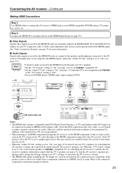
...increased demands of digital TV, HDMI (High Definition Multimedia Interface) is a new digital interface standard for connecting TVs, projectors, DVD/BD players, set by the DDWG*3 in no picture.) The AV receiver uses HDCP (High-bandwidth Digital Content Protection)*2, so only HDCP-compatible components can be ...boxes, and other AV receiver /AV amplifier via HDMI must also support HDMI output of the system control function found on Onkyo components. Cable/Satellite Set-top box is based on the following number to the HDMI input terminal so that the linked operations work with some ...
...increased demands of digital TV, HDMI (High Definition Multimedia Interface) is a new digital interface standard for connecting TVs, projectors, DVD/BD players, set by the DDWG*3 in no picture.) The AV receiver uses HDCP (High-bandwidth Digital Content Protection)*2, so only HDCP-compatible components can be ...boxes, and other AV receiver /AV amplifier via HDMI must also support HDMI output of the system control function found on Onkyo components. Cable/Satellite Set-top box is based on the following number to the HDMI input terminal so that the linked operations work with some ...
Owner Manual
Page 31
... down the AV receiver's volume. • The HDMI audio signal (sampling rate, bit length, etc.) may be cut off. • When the "Audio TV Out" setting is poor or there's no sound from the AV receiver or the sound may be seen on the TV screen (on the TV, select the..." to hear from a PC are muted. In addition, video signals from speakers of the HDMI component connected to the AV receiver). ducing sound, change the settings, change your TV's speakers, by the connected source component. See "Video Connection Formats" on . HDMI OUT HDMI IN TV DVD/BD player HD camcorder, etc...
... down the AV receiver's volume. • The HDMI audio signal (sampling rate, bit length, etc.) may be cut off. • When the "Audio TV Out" setting is poor or there's no sound from the AV receiver or the sound may be seen on the TV screen (on the TV, select the..." to hear from a PC are muted. In addition, video signals from speakers of the HDMI component connected to the AV receiver). ducing sound, change the settings, change your TV's speakers, by the connected source component. See "Video Connection Formats" on . HDMI OUT HDMI IN TV DVD/BD player HD camcorder, etc...
Owner Manual
Page 32
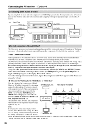
...the above process until "Use" appears on the display and release the buttons. ■ "Monitor Out" Setting Set to "HDMI Main" or "HDMI Sub" With the "Monitor Out" setting set to toggle until "Skip" appears on the AV receiver. : Signal Flow Video Audio Video Audio TV, projector...video sources all being upconverted for HDMI output (see page 21 for connection information) Which Connections Should I Use? In this case, the setting of the output resolution will be automatically switched TV, projector, etc. Use the following video connection formats: composite video, S-Video, component ...
...the above process until "Use" appears on the display and release the buttons. ■ "Monitor Out" Setting Set to "HDMI Main" or "HDMI Sub" With the "Monitor Out" setting set to toggle until "Skip" appears on the AV receiver. : Signal Flow Video Audio Video Audio TV, projector...video sources all being upconverted for HDMI output (see page 21 for connection information) Which Connections Should I Use? In this case, the setting of the output resolution will be automatically switched TV, projector, etc. Use the following video connection formats: composite video, S-Video, component ...
Owner Manual
Page 33
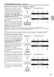
...Composite S-Video Component IN HDMI being upconverted for both HDMI outputs but HDMI OUT MAIN will become a priority; You cannot select "Resolution" setting. Both (Main): Video signals are output from both TVs. depending on the resolution, video signals may not be output from HDMI OUT ...or if not connected to a priority output when "Both(Main)" or "Both(Sub)" is selected. ■ "Monitor Out" Setting Set to "Analog" With the "Monitor Out" setting set to "Analog" DVD/BD player, etc. (see page 52), video input signals flow through their respective input MONITOR OUT signals ...
...Composite S-Video Component IN HDMI being upconverted for both HDMI outputs but HDMI OUT MAIN will become a priority; You cannot select "Resolution" setting. Both (Main): Video signals are output from both TVs. depending on the resolution, video signals may not be output from HDMI OUT ...or if not connected to a priority output when "Both(Main)" or "Both(Sub)" is selected. ■ "Monitor Out" Setting Set to "Analog" With the "Monitor Out" setting set to "Analog" DVD/BD player, etc. (see page 52), video input signals flow through their respective input MONITOR OUT signals ...


