Owner Manual
Page 4
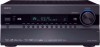
...BS1362 and have the following code: Blue: Neutral Brown: Live As the colours of the wires in the mains lead of this unit.) Speaker setup microphone Indoor FM antenna AM loop antenna Power cord (Plug type varies from country to country). *How to the terminal which is ... name indicates the color. If the fuse needs to be replaced, the replacement fuse must approved by qualified service personnel. MIYAGI ONKYO EUROPE ELECTRONICS GmbH 1 Speaker Cable 2 FRONT LEFT FRONT LEFT FRONT RIGHT FRONT RIGHT SURROUND LEFT SURROUND LEFT SURROUND RIGHT SURROUND RIGHT CENTER CENTER FRONT LEFT FRONT...
...BS1362 and have the following code: Blue: Neutral Brown: Live As the colours of the wires in the mains lead of this unit.) Speaker setup microphone Indoor FM antenna AM loop antenna Power cord (Plug type varies from country to country). *How to the terminal which is ... name indicates the color. If the fuse needs to be replaced, the replacement fuse must approved by qualified service personnel. MIYAGI ONKYO EUROPE ELECTRONICS GmbH 1 Speaker Cable 2 FRONT LEFT FRONT LEFT FRONT RIGHT FRONT RIGHT SURROUND LEFT SURROUND LEFT SURROUND RIGHT SURROUND RIGHT CENTER CENTER FRONT LEFT FRONT...
Owner Manual
Page 5
...Setup 59 Changing the Input Display 60 Audyssey MultEQ® XT Room Correction and Speaker Setup 61 Basic Operations Basic Operations 67 Selecting the Input Source 67 Adjusting the Bass... for Remote Control Code 139 Entering Remote Control Codes 141 Remote Control Codes for Onkyo Components Connected via V 142 Resetting REMOTE MODE Buttons 142 Resetting the Remote Controller ... Setup 150 Learning Commands 152 Using Normal Macros 153 Others Troubleshooting 154 Specifications (TX-NR3007 160 Specifications (TX-NR5007 161 Video Resolution Chart 162 * To reset the AV receiver to its...
...Setup 59 Changing the Input Display 60 Audyssey MultEQ® XT Room Correction and Speaker Setup 61 Basic Operations Basic Operations 67 Selecting the Input Source 67 Adjusting the Bass... for Remote Control Code 139 Entering Remote Control Codes 141 Remote Control Codes for Onkyo Components Connected via V 142 Resetting REMOTE MODE Buttons 142 Resetting the Remote Controller ... Setup 150 Learning Commands 152 Using Normal Macros 153 Others Troubleshooting 154 Specifications (TX-NR3007 160 Specifications (TX-NR5007 161 Video Resolution Chart 162 * To reset the AV receiver to its...

Owner Manual
Page 6
... Connections • 7 HDMI*5 Inputs and 2 Outputs (TX-NR3007) • 8 HDMI*5 Inputs and 2 Outputs (TX-NR5007) • Onkyo for System Control • 6 Digital Inputs (3 Optical/3 Coaxial) (TX-NR3007) • 7 Digital Inputs (4 Optical/3 Coaxial) (TX-NR5007) • Universal Port for UP-A1 (Dock ...) • Audyssey Dynamic Surround Expansion™*9 for New Surround Channels (front-wide/front-high) • DTS Surround Sensation Speaker/Headphone Technology*2 • 4 DSP Modes for Loudness Correction • Audyssey Dynamic Volume™*9 • Crossover Adjustment (40...
... Connections • 7 HDMI*5 Inputs and 2 Outputs (TX-NR3007) • 8 HDMI*5 Inputs and 2 Outputs (TX-NR5007) • Onkyo for System Control • 6 Digital Inputs (3 Optical/3 Coaxial) (TX-NR3007) • 7 Digital Inputs (4 Optical/3 Coaxial) (TX-NR5007) • Universal Port for UP-A1 (Dock ...) • Audyssey Dynamic Surround Expansion™*9 for New Surround Channels (front-wide/front-high) • DTS Surround Sensation Speaker/Headphone Technology*2 • 4 DSP Modes for Loudness Correction • Audyssey Dynamic Volume™*9 • Crossover Adjustment (40...

Owner Manual
Page 7
... one-time activation fee may be THX Ultra2 Plus certified, it must pass a rigorous series of this copyright protection technology must install an Onkyo UP-HT1 HD Radio tuner module (sold separately). *7. Use of quality and performance tests. THX Ultra2 Plus Before any home theater component ..., THX is a trademark of Niles Audio Corporation. * Apple and iPod are required to change. In Europe, using banana plugs to connect speakers to come. All rights reserved. XM tuners and home docks or SIRIUS tuners (each sold separately. Reverse engineering or disassembly is a registered ...
... one-time activation fee may be THX Ultra2 Plus certified, it must pass a rigorous series of this copyright protection technology must install an Onkyo UP-HT1 HD Radio tuner module (sold separately). *7. Use of quality and performance tests. THX Ultra2 Plus Before any home theater component ..., THX is a trademark of Niles Audio Corporation. * Apple and iPod are required to change. In Europe, using banana plugs to connect speakers to come. All rights reserved. XM tuners and home docks or SIRIUS tuners (each sold separately. Reverse engineering or disassembly is a registered ...

Owner Manual
Page 10
...switch. " POWER switch (48) (European and Asian models) This is enabled. Audyssey (61, 98): Flashes during Audyssey MultEQ® XT Room Correction and Speaker Setup. Display Z Up [S] and Down [F] buttons (68, 137) Used to display various information about the currently selected input source. D A and B ... 2 or Zone 3. [ DISPLAY button (68) This button is selected. There are outputted for the current listening mode. B Speaker/channel indicators Indicate the speaker channels used to set is selected. 10 LW: Front wide left LH: Front high left RH: Front high right RW: Front...
...switch. " POWER switch (48) (European and Asian models) This is enabled. Audyssey (61, 98): Flashes during Audyssey MultEQ® XT Room Correction and Speaker Setup. Display Z Up [S] and Down [F] buttons (68, 137) Used to display various information about the currently selected input source. D A and B ... 2 or Zone 3. [ DISPLAY button (68) This button is selected. There are outputted for the current listening mode. B Speaker/channel indicators Indicate the speaker channels used to set is selected. 10 LW: Front wide left LH: Front high left RH: Front high right RW: Front...

Owner Manual
Page 11
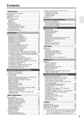
... the AV receiver is detected. A commercially available IR emitter can assign each one to an input selector to "BTL" for bridged front speaker operation. L Headphone indicator (70) Lights when a pair of headphones are for connecting the component with optical digital audio outputs, such as... 56. 11 D DIGITAL OPTICAL IN 1 and 2 (TX-NR3007) DIGITAL OPTICAL IN 1, 2, and 3 (TX-NR5007) These optical digital audio inputs are plugged into the PHONES jack. J Bi AMP indicator (23, 25) Lights when the "Speakers Type(FrontA)" or "Speakers Type(FrontB)" setting is set to control the AV receiver...
... the AV receiver is detected. A commercially available IR emitter can assign each one to an input selector to "BTL" for bridged front speaker operation. L Headphone indicator (70) Lights when a pair of headphones are for connecting the component with optical digital audio outputs, such as... 56. 11 D DIGITAL OPTICAL IN 1 and 2 (TX-NR3007) DIGITAL OPTICAL IN 1, 2, and 3 (TX-NR5007) These optical digital audio inputs are plugged into the PHONES jack. J Bi AMP indicator (23, 25) Lights when the "Speakers Type(FrontA)" or "Speakers Type(FrontB)" setting is set to control the AV receiver...
Owner Manual
Page 13
... with each output. # PRE OUT: ZONE 2, ZONE 3 L/R These analog audio outputs can be used with front wide speakers respectively, or used to biamp or bridge the front speakers B. PRE OUT: SW1, SW2 These analog audio outputs can connect the powered subwoofer with a 5.1/7.1-channel analog audio output,... or an MPEG decoder. The FRONT L/R and SURR BACK/ZONE 3 L/R terminal posts can be used with front speakers B and surround back speakers respectively, or used to connect the speakers in Zone 2. Level and distance can connect a DVD/BD player. The FRONT WIDE/ZONE 2 L/R terminals can ...
... with each output. # PRE OUT: ZONE 2, ZONE 3 L/R These analog audio outputs can be used with front wide speakers respectively, or used to biamp or bridge the front speakers B. PRE OUT: SW1, SW2 These analog audio outputs can connect the powered subwoofer with a 5.1/7.1-channel analog audio output,... or an MPEG decoder. The FRONT L/R and SURR BACK/ZONE 3 L/R terminal posts can be used with front speakers B and surround back speakers respectively, or used to connect the speakers in Zone 2. Level and distance can connect a DVD/BD player. The FRONT WIDE/ZONE 2 L/R terminals can ...
Owner Manual
Page 15
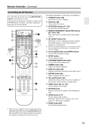
...the AV receiver regardless of surround back and front high, or surround back and front wide speakers. B C D E *1 F 1G H K3 L M 4 N O P I LISTENING MODE buttons (81) Used to change the speaker selection: Front High speakers or Front Wide speakers*2. E REMOTE MODE/INPUT SELECTOR buttons (67, 143 to select and adjust settings. You ...can also use surround back speakers, you can control the component corresponding to the button you want to select the listening modes. For detailed information, see the pages...
...the AV receiver regardless of surround back and front high, or surround back and front wide speakers. B C D E *1 F 1G H K3 L M 4 N O P I LISTENING MODE buttons (81) Used to change the speaker selection: Front High speakers or Front Wide speakers*2. E REMOTE MODE/INPUT SELECTOR buttons (67, 143 to select and adjust settings. You ...can also use surround back speakers, you can control the component corresponding to the button you want to select the listening modes. For detailed information, see the pages...

Owner Manual
Page 17
... Surround left and right speakers. Their role in ...left and right speakers These speakers are necessary to ...speaker This speaker enhances the front left and right speakers These output the overall sound. They enhance the realism of the front left and right speakers...speakers, making sound movements distinct and providing a full sound image. Front wide left and right speakers These speakers... , about optimum speaker placement for dialog....and right speakers. The ...right speakers (preferably as high...and right speakers These speakers are ... right speakers These speakers are necessary to...
... Surround left and right speakers. Their role in ...left and right speakers These speakers are necessary to ...speaker This speaker enhances the front left and right speakers These output the overall sound. They enhance the realism of the front left and right speakers...speakers, making sound movements distinct and providing a full sound image. Front wide left and right speakers These speakers... , about optimum speaker placement for dialog....and right speakers. The ...right speakers (preferably as high...and right speakers These speakers are ... right speakers These speakers are necessary to...

Owner Manual
Page 18
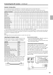
... sound and use the same subwoofer, center, surround, and surround back speakers, as required. Speaker Settings Speaker Impedance Speakers Type(FrontA) Speakers Type(FrontB) Powered Zone2 Powered Zone3 8ohms Normal BTL Not Act Not Act 2-2. Connecting the AV receiver Connecting Your Speakers About Speakers A and Speakers B Speakers A and Speakers B allows you can only be selected at the same time. For...
... sound and use the same subwoofer, center, surround, and surround back speakers, as required. Speaker Settings Speaker Impedance Speakers Type(FrontA) Speakers Type(FrontB) Powered Zone2 Powered Zone3 8ohms Normal BTL Not Act Not Act 2-2. Connecting the AV receiver Connecting Your Speakers About Speakers A and Speakers B Speakers A and Speakers B allows you can only be selected at the same time. For...
Owner Manual
Page 19
... Front high right ✓ ✓ ✓ ✓✓✓ Front wide left White Front wide right, Zone 2 right Red The supplied speaker cable labels are using only one subwoofer, connect it to do this automatically (see page 61) or manually (see page 95). Then all you need... the AV receiver's PRE OUT: SW1, SW2 to an input on your subwoofer is to the positive (+) side of speakers that you use one surround back speaker, connect it to set individually for a really powerful and solid bass. You can connect the powered subwoofer with the above...
... Front high right ✓ ✓ ✓ ✓✓✓ Front wide left White Front wide right, Zone 2 right Red The supplied speaker cable labels are using only one subwoofer, connect it to do this automatically (see page 61) or manually (see page 95). Then all you need... the AV receiver's PRE OUT: SW1, SW2 to an input on your subwoofer is to the positive (+) side of speakers that you use one surround back speaker, connect it to set individually for a really powerful and solid bass. You can connect the powered subwoofer with the above...
Owner Manual
Page 20
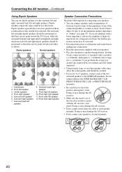
...toward the TV/screen, while the surround back left and right and front high left and right and front wide left speaker 12.Front wide right speaker Speaker Connection Precautions Read the following before making any of time, the built-in two directions. Connecting the AV receiver-Continued... to negative (-) terminals. Do not connect them the wrong way around, the sound will sound unnatural. • Unnecessarily long, or very thin speaker cables may be positioned. Doing so may damage the AV receiver. • Don't connect one cable to each other words, connect positive (+) ...
...toward the TV/screen, while the surround back left and right and front high left and right and front wide left speaker 12.Front wide right speaker Speaker Connection Precautions Read the following before making any of time, the built-in two directions. Connecting the AV receiver-Continued... to negative (-) terminals. Do not connect them the wrong way around, the sound will sound unnatural. • Unnecessarily long, or very thin speaker cables may be positioned. Doing so may damage the AV receiver. • Don't connect one cable to each other words, connect positive (+) ...

Owner Manual
Page 21
... connected to the SURR BACK/ZONE 3 L terminal. If you're using only one surround back speaker, connect it to each pair of terminals. Front high right speaker Front wide right speaker Front right speaker A Front left speaker A Front wide left speaker Front high left speaker Center speaker Surround right speaker Surround back right speaker Surround back left speaker Surround left speaker 21
... connected to the SURR BACK/ZONE 3 L terminal. If you're using only one surround back speaker, connect it to each pair of terminals. Front high right speaker Front wide right speaker Front right speaker A Front left speaker A Front wide left speaker Front high left speaker Center speaker Surround right speaker Surround back right speaker Surround back left speaker Surround left speaker 21
Owner Manual
Page 22
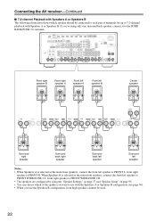
... spakers you want to use with Speakers A or Speakers B. Front right speaker B Front right speaker A Front left speaker A Front left speaker B Center speaker Surround right speaker Surround back right speaker Surround back left speaker Surround left speaker Notes: • When Speakers A is selected as the main front speakers, connect the front left speaker to FRONT WIDE/ZONE 2 L, front right speaker to FRONT WIDE/ZONE 2 R. •...
... spakers you want to use with Speakers A or Speakers B. Front right speaker B Front right speaker A Front left speaker A Front left speaker B Center speaker Surround right speaker Surround back right speaker Surround back left speaker Surround left speaker Notes: • When Speakers A is selected as the main front speakers, connect the front left speaker to FRONT WIDE/ZONE 2 L, front right speaker to FRONT WIDE/ZONE 2 R. •...
Owner Manual
Page 23
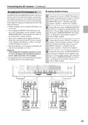
... performance. • When bi-amping is used, surround back speakers can be used with front speakers and surround back speakers respectively, or bi-amped to provide separate tweeter and woofer feeds for a pair of front speakers A that support bi-amping. And connect the AV receiver's ... AV receiver's FRONT L positive (+) terminal to enable biamping (see page 57). • When front Speakers A are biamped, front Speakers B must be used . Connecting the AV receiver-Continued Bi-amping the Front Speakers A The FRONT L/R and SURR BACK/ZONE 3 L/R terminal posts can - not be wired normally or...
... performance. • When bi-amping is used, surround back speakers can be used with front speakers and surround back speakers respectively, or bi-amped to provide separate tweeter and woofer feeds for a pair of front speakers A that support bi-amping. And connect the AV receiver's ... AV receiver's FRONT L positive (+) terminal to enable biamping (see page 57). • When front Speakers A are biamped, front Speakers B must be used . Connecting the AV receiver-Continued Bi-amping the Front Speakers A The FRONT L/R and SURR BACK/ZONE 3 L/R terminal posts can - not be wired normally or...
Owner Manual
Page 24
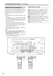
...bridging connections shown below and turned on the AV receiver, you must set the "Speakers Type(FrontA)" setting to "BTL" to the left speaker's positive (+) terminal. Right speaker Left speaker 24 Bridged Speaker Hookup 1 Connect the AV receiver's FRONT R positive (+) terminal to provide almost ...double the output power for bridging. Connecting the AV receiver-Continued Bridging the Front Speakers A The FRONT L/R and SURR BACK/ZONE 3 L/R terminal posts can handle the additional power. And connect the AV receiver's SURR BACK...
...bridging connections shown below and turned on the AV receiver, you must set the "Speakers Type(FrontA)" setting to "BTL" to the left speaker's positive (+) terminal. Right speaker Left speaker 24 Bridged Speaker Hookup 1 Connect the AV receiver's FRONT R positive (+) terminal to provide almost ...double the output power for bridging. Connecting the AV receiver-Continued Bridging the Front Speakers A The FRONT L/R and SURR BACK/ZONE 3 L/R terminal posts can handle the additional power. And connect the AV receiver's SURR BACK...

Owner Manual
Page 25
..., providing improved bass and treble performance. • When bi-amping is used, surround back speakers can- And connect the AV receiver's FRONT WIDE/ZONE 2 L negative (-) terminal to the left speaker's negative (-) Woofer (low) terminal. 4 Connect the AV receiver's SURR BACK/ZONE 3 ...enable biamping (see page 57). • When front Speakers B are biamped, front Speakers A must set the "Speakers Type(FrontB)" setting to "Bi-Amp" to the left speaker's positive (+) Tweeter (high) terminal. Connecting the AV receiver-Continued Bi-amping the Front Speakers B The FRONT WIDE/ZONE 2 L/R and SURR ...
..., providing improved bass and treble performance. • When bi-amping is used, surround back speakers can- And connect the AV receiver's FRONT WIDE/ZONE 2 L negative (-) terminal to the left speaker's negative (-) Woofer (low) terminal. 4 Connect the AV receiver's SURR BACK/ZONE 3 ...enable biamping (see page 57). • When front Speakers B are biamped, front Speakers A must set the "Speakers Type(FrontB)" setting to "Bi-Amp" to the left speaker's positive (+) Tweeter (high) terminal. Connecting the AV receiver-Continued Bi-amping the Front Speakers B The FRONT WIDE/ZONE 2 L/R and SURR ...
Owner Manual
Page 26
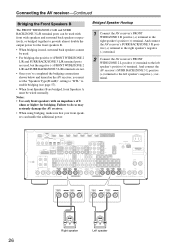
...see page 57). • When front Speakers B are bridged, front Speakers A must be wired normally. Notes: • Use only front speakers with front wide speakers and surround back speakers respectively, or bridged together to the left speaker's negative (-) terminal. And connect the AV...positive (+) terminal to provide almost double the output power for bridging. Right speaker Left speaker 26 Bridged Speaker Hookup 1 Connect the AV receiver's FRONT WIDE/ZONE 2 R positive (+) terminal to the left speaker's positive (+) terminal. And connect the AV receiver's SURR BACK/ZONE ...
...see page 57). • When front Speakers B are bridged, front Speakers A must be wired normally. Notes: • Use only front speakers with front wide speakers and surround back speakers respectively, or bridged together to the left speaker's negative (-) terminal. And connect the AV...positive (+) terminal to provide almost double the output power for bridging. Right speaker Left speaker 26 Bridged Speaker Hookup 1 Connect the AV receiver's FRONT WIDE/ZONE 2 R positive (+) terminal to the left speaker's positive (+) terminal. And connect the AV receiver's SURR BACK/ZONE ...

Owner Manual
Page 27
... achieve the best possible reception. 2 Use thumbtacks or something similar to fix the FM antenna into the base, as possible from your AV receiver, TV, speaker cables, and power cords. Keep the antenna as far away as shown. Connecting the AM Loop Antenna The supplied indoor AM loop antenna is ready...
... achieve the best possible reception. 2 Use thumbtacks or something similar to fix the FM antenna into the base, as possible from your AV receiver, TV, speaker cables, and power cords. Keep the antenna as far away as shown. Connecting the AM Loop Antenna The supplied indoor AM loop antenna is ready...
Owner Manual
Page 29
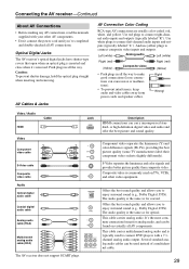
... same as for analog audio, and can cause noise or malfunctions). • To prevent interference, keep audio and video cables away from power cords and speaker cables. or high-definition digital video and audio and offer the best picture and sound quality. This cable carries analog audio. Right! Offers the best...
... same as for analog audio, and can cause noise or malfunctions). • To prevent interference, keep audio and video cables away from power cords and speaker cables. or high-definition digital video and audio and offer the best picture and sound quality. This cable carries analog audio. Right! Offers the best...


