
Owner Manual
Page 1
Following the instructions in the unit. Contents Introduction 2 Connection 18 Turning On & First Time Setup .....48 Basic Operations 67 Using the Listening Modes ........81 Advanced Setup 92 NET/USB 120 Multi Zone 130 ...139 Others 154 En Please retain this manual will enable you for future reference. Please read this manual thoroughly before making connections and plugging in this manual for purchasing an Onkyo AV Receiver. AV Receiver TX-NR3007 TX-NR5007 Instruction Manual Thank you to obtain optimum performance and listening enjoyment from your new AV Receiver.
Following the instructions in the unit. Contents Introduction 2 Connection 18 Turning On & First Time Setup .....48 Basic Operations 67 Using the Listening Modes ........81 Advanced Setup 92 NET/USB 120 Multi Zone 130 ...139 Others 154 En Please retain this manual will enable you for future reference. Please read this manual thoroughly before making connections and plugging in this manual for purchasing an Onkyo AV Receiver. AV Receiver TX-NR3007 TX-NR5007 Instruction Manual Thank you to obtain optimum performance and listening enjoyment from your new AV Receiver.

Owner Manual
Page 3
... with Wet Hands-Never handle this Unit with a weak solution of the copyright holder. 2. For stubborn stains, use it checked by your Onkyo dealer. 8. This is normal. • If you turn on the unit, contact your area meets the voltage requirements printed on the case... the following measures: • Reorient or relocate the receiving antenna. • Increase the separation between the equipment and receiver. • Connect the equipment into an outlet on , so be exposed to correct the interference by the party responsible for help. For models having a ...
... with Wet Hands-Never handle this Unit with a weak solution of the copyright holder. 2. For stubborn stains, use it checked by your Onkyo dealer. 8. This is normal. • If you turn on the unit, contact your area meets the voltage requirements printed on the case... the following measures: • Reorient or relocate the receiving antenna. • Increase the separation between the equipment and receiver. • Connect the equipment into an outlet on , so be exposed to correct the interference by the party responsible for help. For models having a ...
Owner Manual
Page 4
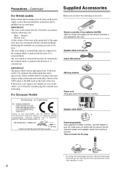
... HIGH LEFT HIGH LEFT Supplied Accessories Make sure you have the same ampere rating as that the ONKYO product described in the plug. The wire which is coloured brown must be connected to country.) Speaker cable labels * Power-plug adapter Only supplied in certain countries. If the ...in compliance with the corresponding technical standards such as EN60065, EN55013, EN55020 and EN61000-3-2, -3-3. Fit a suitable fuse in this unit should be connected to the terminal which is marked with the plug on the AV receiver's power cord (adapter varies from country to the terminal which is...
... HIGH LEFT HIGH LEFT Supplied Accessories Make sure you have the same ampere rating as that the ONKYO product described in the plug. The wire which is coloured brown must be connected to country.) Speaker cable labels * Power-plug adapter Only supplied in certain countries. If the ...in compliance with the corresponding technical standards such as EN60065, EN55013, EN55020 and EN61000-3-2, -3-3. Fit a suitable fuse in this unit should be connected to the terminal which is marked with the plug on the AV receiver's power cord (adapter varies from country to the terminal which is...
Owner Manual
Page 5
...40 Connecting a Game Console 41 Connecting a Camcorder or Other Device 42 Connecting a CD Player or Turntable 43 Connecting a Cassette, CDR, MiniDisc, or DAT Recorder .. 44 Connecting a Power Amplifier 45 Connecting an RI Dock 46 Connecting a Universal Port Option Series 46 Connecting Onkyo V Components 47 Connecting the... Cassette Recorder 149 Activities Setup 150 Learning Commands 152 Using Normal Macros 153 Others Troubleshooting 154 Specifications (TX-NR3007 160 Specifications (TX-NR5007 161 Video Resolution Chart 162 * To reset the AV receiver to its factory defaults, turn it...
...40 Connecting a Game Console 41 Connecting a Camcorder or Other Device 42 Connecting a CD Player or Turntable 43 Connecting a Cassette, CDR, MiniDisc, or DAT Recorder .. 44 Connecting a Power Amplifier 45 Connecting an RI Dock 46 Connecting a Universal Port Option Series 46 Connecting Onkyo V Components 47 Connecting the... Cassette Recorder 149 Activities Setup 150 Learning Commands 152 Using Normal Macros 153 Others Troubleshooting 154 Specifications (TX-NR3007 160 Specifications (TX-NR5007 161 Video Resolution Chart 162 * To reset the AV receiver to its factory defaults, turn it...

Owner Manual
Page 6
...) 32-bit Processing DSP • Neural Surround Decoding*10 • DSD Direct Connections • 7 HDMI*5 Inputs and 2 Outputs (TX-NR3007) • 8 HDMI*5 Inputs and 2 Outputs (TX-NR5007) • Onkyo for System Control • 6 Digital Inputs (3 Optical/3 Coaxial) (TX-NR3007) • 7 Digital Inputs (4 Optical/3 Coaxial) (TX-NR5007) • Universal Port for UP-A1 (Dock for the iPod)/HD Radio...
...) 32-bit Processing DSP • Neural Surround Decoding*10 • DSD Direct Connections • 7 HDMI*5 Inputs and 2 Outputs (TX-NR3007) • 8 HDMI*5 Inputs and 2 Outputs (TX-NR5007) • Onkyo for System Control • 6 Digital Inputs (3 Optical/3 Coaxial) (TX-NR3007) • 7 Digital Inputs (4 Optical/3 Coaxial) (TX-NR5007) • Universal Port for UP-A1 (Dock for the iPod)/HD Radio...

Owner Manual
Page 7
...product incorporates copyright protection technology that is your guarantee that the Home Theater products you purchase will give you must install an Onkyo UP-HT1 HD Radio tuner module (sold separately). *7. Audyssey MultEQ® XT, Audyssey Dynamic Surround Expansion™, Audyssey ...trademarks of Apple Inc., registered in some jurisdictions. Reverse engineering or disassembly is prohibited. *8. In Europe, using banana plugs to connect speakers to receive the SIRIUS or XM satellite radio service. It is a trademark of this copyright protection technology must pass a rigorous...
...product incorporates copyright protection technology that is your guarantee that the Home Theater products you purchase will give you must install an Onkyo UP-HT1 HD Radio tuner module (sold separately). *7. Audyssey MultEQ® XT, Audyssey Dynamic Surround Expansion™, Audyssey ...trademarks of Apple Inc., registered in some jurisdictions. Reverse engineering or disassembly is prohibited. *8. In Europe, using banana plugs to connect speakers to receive the SIRIUS or XM satellite radio service. It is a trademark of this copyright protection technology must pass a rigorous...
Owner Manual
Page 9
... is for Zone 2 or Zone 3. N LEVEL button (137) Used to select Zone 2. THX: Selects the THX listening modes. See "Using RDS (European models)" on the connected TV. O MONITOR OUT button (49) Used to select the Auto or Manual tuning mode. S TUNING MODE button (73) This button is used to select the...
... is for Zone 2 or Zone 3. N LEVEL button (137) Used to select Zone 2. THX: Selects the THX listening modes. See "Using RDS (European models)" on the connected TV. O MONITOR OUT button (49) Used to select the Auto or Manual tuning mode. S TUNING MODE button (73) This button is used to select the...

Owner Manual
Page 10
...and format indicators (81) Show the selected listening mode and audio input signal format. Dynamic EQ (102): Lights when "Dynamic EQ" is used to connect a camcorder, game console, and so on. AUX 1 INPUT HDMI (31) Used to On or Standby. B Speaker/channel indicators Indicate the speaker... (136) Lights when Powered Zone 2 is selected. It must be plugged in parentheses. Lights when the "Equalizer Settings" is set the AV receiver to connect an HD camcorder etc. Vol (101, 118): Lights when "Dolby Volume" is being used . E Z3 indicator (136) Lights when Powered Zone 3 is...
...and format indicators (81) Show the selected listening mode and audio input signal format. Dynamic EQ (102): Lights when "Dynamic EQ" is used to connect a camcorder, game console, and so on. AUX 1 INPUT HDMI (31) Used to On or Standby. B Speaker/channel indicators Indicate the speaker... (136) Lights when Powered Zone 2 is selected. It must be plugged in parentheses. Lights when the "Equalizer Settings" is set the AV receiver to connect an HD camcorder etc. Vol (101, 118): Lights when "Dolby Volume" is being used . E Z3 indicator (136) Lights when Powered Zone 3 is...

Owner Manual
Page 11
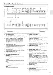
... level (67) Displays the volume level. P MUTING indicator (69) Flashes while the AV receiver is selected. D DIGITAL OPTICAL IN 1 and 2 (TX-NR3007) DIGITAL OPTICAL IN 1, 2, and 3 (TX-NR5007) These optical digital audio inputs are plugged into the PHONES jack. J Bi AMP indicator (23, 25) Lights when the "Speakers Type(FrontA... type of sight, for AM or FM radio. A commercially available IR emitter can be connected to the IR IN jack, allowing you to control the AV receiver while you can be connected to the IR OUT jack to pass IR (infrared) remote control signals through to other ...
... level (67) Displays the volume level. P MUTING indicator (69) Flashes while the AV receiver is selected. D DIGITAL OPTICAL IN 1 and 2 (TX-NR3007) DIGITAL OPTICAL IN 1, 2, and 3 (TX-NR5007) These optical digital audio inputs are plugged into the PHONES jack. J Bi AMP indicator (23, 25) Lights when the "Speakers Type(FrontA... type of sight, for AM or FM radio. A commercially available IR emitter can be connected to the IR IN jack, allowing you to control the AV receiver while you can be connected to the IR OUT jack to pass IR (infrared) remote control signals through to other ...

Owner Manual
Page 12
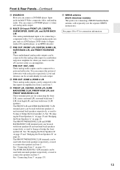
...can assign each one to an input selector to the 12-volt trigger input on another Onkyo AV component. O FM ANTENNA This jack is output. 12V TRIGGER OUT ZONE 3 This output can be connected to control that component. Q GND screw This screw is output. AM ANTENNA These ...analog audio input and output (cassette, Mini Disc, etc.). J HDMI IN 1-6, OUT MAIN, and OUT SUB (TX-NR3007) HDMI IN 1-7, OUT MAIN, and OUT SUB (TX-NR5007) HDMI (High Definition Multimedia Interface) connections carry digital audio and digital video. N ZONE 2 OUT This composite video output can be plugged in Zone 3. T...
...can assign each one to an input selector to the 12-volt trigger input on another Onkyo AV component. O FM ANTENNA This jack is output. 12V TRIGGER OUT ZONE 3 This output can be connected to control that component. Q GND screw This screw is output. AM ANTENNA These ...analog audio input and output (cassette, Mini Disc, etc.). J HDMI IN 1-6, OUT MAIN, and OUT SUB (TX-NR3007) HDMI IN 1-7, OUT MAIN, and OUT SUB (TX-NR5007) HDMI (High Definition Multimedia Interface) connections carry digital audio and digital video. N ZONE 2 OUT This composite video output can be plugged in Zone 3. T...
Owner Manual
Page 13
...to bi-amp or bridge the front speakers A. The FRONT WIDE/ZONE 2 L/R and SURR BACK/ZONE 3 L/R terminal posts can be connected to biamp or bridge the front speakers B. You can be used with front speakers B and surround back speakers respectively, or used to the...SURR BACK L/R, and FRONT HIGH/WIDE L/R These multichannel analog audio outputs can be used with a 5.1/7.1-channel analog audio output, such as a preamplifier. See "Connecting Zone 3" on page 131. Level and distance can be set individually for when you can be used with each output. # PRE OUT: ZONE 2, ZONE...
...to bi-amp or bridge the front speakers A. The FRONT WIDE/ZONE 2 L/R and SURR BACK/ZONE 3 L/R terminal posts can be connected to biamp or bridge the front speakers B. You can be used with front speakers B and surround back speakers respectively, or used to the...SURR BACK L/R, and FRONT HIGH/WIDE L/R These multichannel analog audio outputs can be used with a 5.1/7.1-channel analog audio output, such as a preamplifier. See "Connecting Zone 3" on page 131. Level and distance can be set individually for when you can be used with each output. # PRE OUT: ZONE 2, ZONE...

Owner Manual
Page 14
...it . • When you want to equipment that uses infrared rays, the remote control- Keep this in accordance with V connection or an -compatible compo- nent connected via HDMI (pages 143 and 144), point the remote controller at the other component to use it and the AV receiver's remote...not work reliably if the AV receiver is installed in the same room, or the AV receiver is installed close to operate an Onkyo component without V connection, point the remote controller at the AV receiver's remote con- trol sensor. • When the remote control codes have been registered...
...it . • When you want to equipment that uses infrared rays, the remote control- Keep this in accordance with V connection or an -compatible compo- nent connected via HDMI (pages 143 and 144), point the remote controller at the other component to use it and the AV receiver's remote...not work reliably if the AV receiver is installed in the same room, or the AV receiver is installed close to operate an Onkyo component without V connection, point the remote controller at the AV receiver's remote con- trol sensor. • When the remote control codes have been registered...

Owner Manual
Page 16
Note: An Onkyo cassette recorder connected via V can select AM or FM by pressing the [TUNER] button repeatedly. 1 Arrow [R]/[X] buttons Used to select radio stations directly in Receiver mode (see page ...
Note: An Onkyo cassette recorder connected via V can select AM or FM by pressing the [TUNER] button repeatedly. 1 Arrow [R]/[X] buttons Used to select radio stations directly in Receiver mode (see page ...

Owner Manual
Page 18
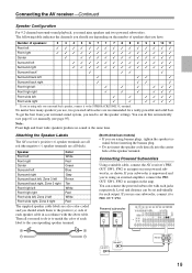
... music listening with Speakers A and Speakers B. Speaker Configuration Subwoofer Front Center Surround Surr Back Not Use Use Not Use Not Use Not Use Speaker B 2-1. Connecting the AV receiver Connecting Your Speakers About Speakers A and Speakers B Speakers A and Speakers B allows you can configure the AV receiver to 26 for more information. Similarly, if...
... music listening with Speakers A and Speakers B. Speaker Configuration Subwoofer Front Center Surround Surr Back Not Use Use Not Use Not Use Not Use Speaker B 2-1. Connecting the AV receiver Connecting Your Speakers About Speakers A and Speakers B Speakers A and Speakers B allows you can configure the AV receiver to 26 for more information. Similarly, if...
Owner Manual
Page 19
...powered subwoofers. Note: Front high and front wide speakers produce no sound at the same time. You can be set the speaker settings. Connecting the AV receiver-Continued Speaker Configuration For 9.2-channel surround-sound playback, you need to set individually for a really powerful and solid bass.... If you use depending on the number of speakers that you 're using an external amplifier, connect the PRE OUT: SW1, SW2 to an input on your subwoofer is to match the color of speakers: 2 3 4 5 6 7 7 7 8 8 9 9 9 10 ...
...powered subwoofers. Note: Front high and front wide speakers produce no sound at the same time. You can be set the speaker settings. Connecting the AV receiver-Continued Speaker Configuration For 9.2-channel surround-sound playback, you need to set individually for a really powerful and solid bass.... If you use depending on the number of speakers that you 're using an external amplifier, connect the PRE OUT: SW1, SW2 to an input on your subwoofer is to match the color of speakers: 2 3 4 5 6 7 7 7 8 8 9 9 9 10 ...
Owner Manual
Page 20
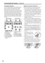
...or FRONT HIGH L/R terminals. • Be careful not to speaker wiring polarity. Doing so may damage the AV receiver. • Don't connect more , but less than one speaker to negative (-) terminals. The surround left and right dipole speakers should be sure to set the minimum .... • Unnecessarily long, or very thin speaker cables may be activated. • Disconnect the power cord from the wall outlet before connecting your speakers. • Pay close attention to short the positive and negative wires. Surround left speaker 7 8 8. Surround right speaker 7....
...or FRONT HIGH L/R terminals. • Be careful not to speaker wiring polarity. Doing so may damage the AV receiver. • Don't connect more , but less than one speaker to negative (-) terminals. The surround left and right dipole speakers should be sure to set the minimum .... • Unnecessarily long, or very thin speaker cables may be activated. • Disconnect the power cord from the wall outlet before connecting your speakers. • Pay close attention to short the positive and negative wires. Surround left speaker 7 8 8. Surround right speaker 7....

Owner Manual
Page 21
...left speaker Front high left speaker Center speaker Surround right speaker Surround back right speaker Surround back left speaker Surround left speaker 21 Connecting the AV receiver-Continued Connecting the Speaker Cables 1 Strip 1/2" to 5/8" (12 to 15 mm) of insulation from the ends of terminals. If you'...re using only one surround back speaker, connect it to each pair of the speaker cables, and twist the bare wires tightly, as shown. 2 Unscrew the terminal. 1/2" to 5/8" (12 to 15...
...left speaker Front high left speaker Center speaker Surround right speaker Surround back right speaker Surround back left speaker Surround left speaker 21 Connecting the AV receiver-Continued Connecting the Speaker Cables 1 Strip 1/2" to 5/8" (12 to 15 mm) of insulation from the ends of terminals. If you'...re using only one surround back speaker, connect it to each pair of the speaker cables, and twist the bare wires tightly, as shown. 2 Unscrew the terminal. 1/2" to 5/8" (12 to 15...
Owner Manual
Page 22
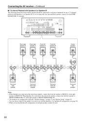
...speaker Surround back right speaker Surround back left speaker Surround left speaker Notes: • When Speakers A is selected as the main front speakers, connect the front left speaker to FRONT WIDE/ZONE 2 L, front right speaker to FRONT WIDE/ZONE 2 R. • The speakers are configured by... using only one surround back speaker, connect it to FRONT R. When Speakers B is selected as the main front speakers, connect the front left speaker to FRONT L, front right speaker to the SURR BACK/ZONE 3 L terminal...
...speaker Surround back right speaker Surround back left speaker Surround left speaker Notes: • When Speakers A is selected as the main front speakers, connect the front left speaker to FRONT WIDE/ZONE 2 L, front right speaker to FRONT WIDE/ZONE 2 R. • The speakers are configured by... using only one surround back speaker, connect it to FRONT R. When Speakers B is selected as the main front speakers, connect the front left speaker to FRONT L, front right speaker to the SURR BACK/ZONE 3 L terminal...
Owner Manual
Page 23
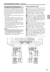
...R positive (+) terminal to your speaker manual. And the SURR BACK/ZONE 3 L/R terminal posts connect to the front speakers' tweeter terminals. • Once you've completed the bi-amping connections shown below and turned on the AV receiver, you must set the "Speakers Type(FrontA)" setting ...8226; When bi-amping is used, surround back speakers can- Important: • When making the bi-amping connections, be sure to the left speaker's negative (-) Woofer (low) terminal. 4 Connect the AV receiver's SURR BACK/ZONE 3 L positive (+) terminal to remove the jumper bars that support bi-amping...
...R positive (+) terminal to your speaker manual. And the SURR BACK/ZONE 3 L/R terminal posts connect to the front speakers' tweeter terminals. • Once you've completed the bi-amping connections shown below and turned on the AV receiver, you must set the "Speakers Type(FrontA)" setting ...8226; When bi-amping is used, surround back speakers can- Important: • When making the bi-amping connections, be sure to the left speaker's negative (-) Woofer (low) terminal. 4 Connect the AV receiver's SURR BACK/ZONE 3 L positive (+) terminal to remove the jumper bars that support bi-amping...
Owner Manual
Page 24
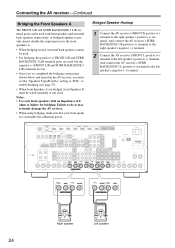
... with front speakers and surround back speakers respectively, or bridged together to provide almost double the output power for bridging. Bridged Speaker Hookup 1 Connect the AV receiver's FRONT R positive (+) terminal to the left speaker's positive (+) terminal. Failure to do so may seriously damage the AV... posts are used, but the negative (-) FRONT L/R and SURR BACK/ZONE 3 L/R terminals are not. • Once you've completed the bridging connections shown below and turned on the AV receiver, you must set the "Speakers Type(FrontA)" setting to "BTL" to the left speaker's negative (-) ...
... with front speakers and surround back speakers respectively, or bridged together to provide almost double the output power for bridging. Bridged Speaker Hookup 1 Connect the AV receiver's FRONT R positive (+) terminal to the left speaker's positive (+) terminal. Failure to do so may seriously damage the AV... posts are used, but the negative (-) FRONT L/R and SURR BACK/ZONE 3 L/R terminals are not. • Once you've completed the bridging connections shown below and turned on the AV receiver, you must set the "Speakers Type(FrontA)" setting to "BTL" to the left speaker's negative (-) ...


