
Owner Manual
Page 2
... THE CANADIAN DEPARTMENT OF COMMUNICATIONS. • Sur les modeles dont la fiche est polarisee. Please read this manual for purchasing the Onkyo TX-DS838 Audio Video Control Receiver. Please retain this manual thoroughly before making connections and operating the unit. and Canadian models are designed to...Tuner Features ■ 40 AM/FM random presets with four-group classification ■ Direct access tuning ■ Automatic FM scanning ■ 8-Character input ■ RDS with PS/PTY/TP/RT (European models) 2 FOR USA MODEL Note to CATV system installer: • This reminder is in ...
... THE CANADIAN DEPARTMENT OF COMMUNICATIONS. • Sur les modeles dont la fiche est polarisee. Please read this manual for purchasing the Onkyo TX-DS838 Audio Video Control Receiver. Please retain this manual thoroughly before making connections and operating the unit. and Canadian models are designed to...Tuner Features ■ 40 AM/FM random presets with four-group classification ■ Direct access tuning ■ Automatic FM scanning ■ 8-Character input ■ RDS with PS/PTY/TP/RT (European models) 2 FOR USA MODEL Note to CATV system installer: • This reminder is in ...
Owner Manual
Page 7
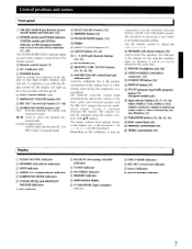
... is received from the remote control. • Remote control sensor [5] ® AC-3 indicator [42] C) DIMMER button Used to -4 input selector indicator ® SURROUND MODE indicators ® CINEMA RE-EQ and MIDNIGHT THEATER indicators • RDS indicator ® FM MUTE (FM...ON/OFF indicators C) TUNED indicator C) FM STEREO indicator © MEMORY indicator © Multi-function display C) T-2 MONITOR (Tape-2 monitor) indicator C) INPUT MODE indicators C) REC OUT (record out) indicator C) Source indicators © MULTI SOURCE indicator 7 Use the remote control to select the desired AC...
... is received from the remote control. • Remote control sensor [5] ® AC-3 indicator [42] C) DIMMER button Used to -4 input selector indicator ® SURROUND MODE indicators ® CINEMA RE-EQ and MIDNIGHT THEATER indicators • RDS indicator ® FM MUTE (FM...ON/OFF indicators C) TUNED indicator C) FM STEREO indicator © MEMORY indicator © Multi-function display C) T-2 MONITOR (Tape-2 monitor) indicator C) INPUT MODE indicators C) REC OUT (record out) indicator C) Source indicators © MULTI SOURCE indicator 7 Use the remote control to select the desired AC...
Owner Manual
Page 8
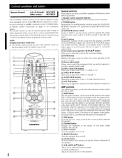
...volume adjustment of time remaining. O Device select switch Allows you to select the component that you to enter a remote control code. O INPUT SELECTOR buttons Allow you wish to operate or to select from the subroom. O ENTER button Displays the Menu screen or enters the cursor ...up each press of the speakers. Control positions and names Remote Control U.S. & Canada: RC-P101S Other areas: RC-P201S The TX-DS838's remote control can be used to operate components equipped with an Onkyo RI (Remote Interactive) connector and connected to program a device code.
...volume adjustment of time remaining. O Device select switch Allows you to select the component that you to enter a remote control code. O INPUT SELECTOR buttons Allow you wish to operate or to select from the subroom. O ENTER button Displays the Menu screen or enters the cursor ...up each press of the speakers. Control positions and names Remote Control U.S. & Canada: RC-P101S Other areas: RC-P201S The TX-DS838's remote control can be used to operate components equipped with an Onkyo RI (Remote Interactive) connector and connected to program a device code.
Owner Manual
Page 13
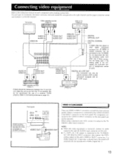
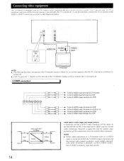
.... (Refer to Connecting antennas on the rear panel cannot be used. Video cassette recorder (Video-1) If there should be connected to the TX-DS838. When a component is not connected, the multi-room system or headphones cannot be operated. If the analog cable is connected to the ...and marked L) to the left channel. If a Dolby Digital (AC-3) laser disc is connected to the TX-DS838's AC-3 RF DIGITAL INPUT connector, also connect the VDP's analog output to this unit's VIDEO-4 INPUT connectors. TV/monitor Video cassette recorder (Video-2) DVD or TV (Video-3) 000 AUDIO IN VIDEO IN -r...
.... (Refer to Connecting antennas on the rear panel cannot be used. Video cassette recorder (Video-1) If there should be connected to the TX-DS838. When a component is not connected, the multi-room system or headphones cannot be operated. If the analog cable is connected to the ...and marked L) to the left channel. If a Dolby Digital (AC-3) laser disc is connected to the TX-DS838's AC-3 RF DIGITAL INPUT connector, also connect the VDP's analog output to this unit's VIDEO-4 INPUT connectors. TV/monitor Video cassette recorder (Video-2) DVD or TV (Video-3) 000 AUDIO IN VIDEO IN -r...
Owner Manual
Page 14
..., and turns off the receiver's power 5 seconds after the TV is turned on the left side of a VCR S Input Video Video signal flow TX-DS838 S Priority Output Video Video and S-VIDEO input and output priority A signal fed into the normal video connector will be output only from both the S-VIDEO output connector... terminal of a VDP To the S-VIDEO output terminal of a DVD or TV To the S-VIDEO output terminal of a VCR To the S-VIDEO input terminal of the TX-DS838's display and five minutes later it also turns off , "•" flashes on or before it is turned off. • If the TV goes...
..., and turns off the receiver's power 5 seconds after the TV is turned on the left side of a VCR S Input Video Video signal flow TX-DS838 S Priority Output Video Video and S-VIDEO input and output priority A signal fed into the normal video connector will be output only from both the S-VIDEO output connector... terminal of a VDP To the S-VIDEO output terminal of a DVD or TV To the S-VIDEO output terminal of a VCR To the S-VIDEO input terminal of the TX-DS838's display and five minutes later it also turns off , "•" flashes on or before it is turned off. • If the TV goes...
Owner Manual
Page 17
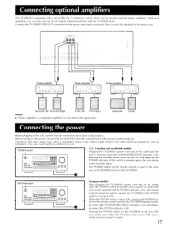
...the MASTER VOLUME control knob is fully turned counterclockwise. If this switch is lit). Connect the TX-DS838's PRE OUT connectors to the power amp input connectors, then connect the speakers to operate the TX-DS838 if the SYSTEM switch is used .) 17 Turning on the unit and lights up the POWER..., such as the POWER switch on the remote control is not set of power is lit). SYSTEM switch =000 European models: After plugging the TX-DS838's power cord into an AC outlet puts the unit in the same way as computers. Subwoofer Center III ' I 0©00* U.S., Canadian and...
...the MASTER VOLUME control knob is fully turned counterclockwise. If this switch is lit). Connect the TX-DS838's PRE OUT connectors to the power amp input connectors, then connect the speakers to operate the TX-DS838 if the SYSTEM switch is used .) 17 Turning on the unit and lights up the POWER..., such as the POWER switch on the remote control is not set of power is lit). SYSTEM switch =000 European models: After plugging the TX-DS838's power cord into an AC outlet puts the unit in the same way as computers. Subwoofer Center III ' I 0©00* U.S., Canadian and...
Owner Manual
Page 22
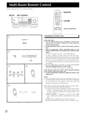
... OFF button on the display. The MULTI SOURCE indicator in the sub-room. Press the appropriate INPUT SELECTOR button on the TX-DS838 in the main room to make the indi- The MULTI SOURCE level appears on the TX-DS838 to check whether it . Multi-Room Remote Control Refer to the desired level. a 3 \\ „ ...the volume to pages 20 and 21 for connection details. If it is not, refer to page 5. • When operating a component not bearing Onkyo's RI mark, check that the MR OFF indicator on the main unit, then while the MULTI SOURCE indicator flashes, use the remote control to ...
... OFF button on the display. The MULTI SOURCE indicator in the sub-room. Press the appropriate INPUT SELECTOR button on the TX-DS838 in the main room to make the indi- The MULTI SOURCE level appears on the TX-DS838 to check whether it . Multi-Room Remote Control Refer to the desired level. a 3 \\ „ ...the volume to pages 20 and 21 for connection details. If it is not, refer to page 5. • When operating a component not bearing Onkyo's RI mark, check that the MR OFF indicator on the main unit, then while the MULTI SOURCE indicator flashes, use the remote control to ...
Owner Manual
Page 23
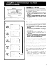
... AUTO" is positioned over certain items may display a sub-screen. After all of the selected background color. NOTE: • Be sure to select the correct input on a setting) and enter the desired settings. 1. p N Iu N - Basic operation Use the remote control to display the Menu screen. 2. Press the ENTER button on...move the cursor to IESC in the screen and press the ENTER button on the remote control to return to the TV/monitor's VIDEO 1 INPUT, VIDEO 1 must be selected on the TV/rnonitor.) • When using the -1or P. Since the on the screen scrolls with a video...
... AUTO" is positioned over certain items may display a sub-screen. After all of the selected background color. NOTE: • Be sure to select the correct input on a setting) and enter the desired settings. 1. p N Iu N - Basic operation Use the remote control to display the Menu screen. 2. Press the ENTER button on...move the cursor to IESC in the screen and press the ENTER button on the remote control to return to the TV/monitor's VIDEO 1 INPUT, VIDEO 1 must be selected on the TV/rnonitor.) • When using the -1or P. Since the on the screen scrolls with a video...
Owner Manual
Page 24
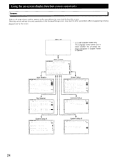
... by the cursor. Menu off * U.S. Menu screen C:12•T1S,I Len II un inn ROI E101 ESC un CIE . p A rci vIDP, • VID I I , C• * * * ESC Input Selector ctar.rxc-tirot ONKYO 1 Rec Selector -. Selecting certain settings for more details about the screen.
... by the cursor. Menu off * U.S. Menu screen C:12•T1S,I Len II un inn ROI E101 ESC un CIE . p A rci vIDP, • VID I I , C• * * * ESC Input Selector ctar.rxc-tirot ONKYO 1 Rec Selector -. Selecting certain settings for more details about the screen.
Owner Manual
Page 25
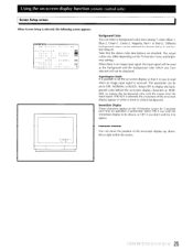
...colors may differ depending on -screen display up, down, left or right within the screen. 25 When there is an image input signal, the input signal will be used as the background and the background color which you have selected will not be shown, or OFF if you..., Red-1 or Red-2). Using the on-screen display function (remote control only) Screen Setup screen When Screen Setup is selected, the following screen appears: 10.1\TX.,C40. ** Screen Setup ** Background Color A BLUE -1 Color 3 = GREEN GB Superimpose Mode = NORMAL GM Smmediate Display , ON BrI Character Position VIDEO -1 C...
...colors may differ depending on -screen display up, down, left or right within the screen. 25 When there is an image input signal, the input signal will be used as the background and the background color which you have selected will not be shown, or OFF if you..., Red-1 or Red-2). Using the on-screen display function (remote control only) Screen Setup screen When Screen Setup is selected, the following screen appears: 10.1\TX.,C40. ** Screen Setup ** Background Color A BLUE -1 Color 3 = GREEN GB Superimpose Mode = NORMAL GM Smmediate Display , ON BrI Character Position VIDEO -1 C...

Owner Manual
Page 29
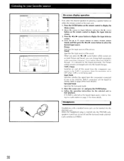
Press either the POWER button on the remote control or the POWER switch (SYSTEM on the European models) on the main unit to the selected input mode lights up . 3. The corresponding indicator (SPEAKERS A or B) lights up . For FM or AM reception, the band and the frequency will appear on ...the power. DIGITAL I 3 0 0 1. Follow the operating instructions for more details on the main unit is chosen as the source, press the INPUT MODE button to 45. 4. NOTE: The TREBLE, MIDBASS and BASS control knobs only affect the left/right front and center speakers. 29 When the CD...
Press either the POWER button on the remote control or the POWER switch (SYSTEM on the European models) on the main unit to the selected input mode lights up . 3. The corresponding indicator (SPEAKERS A or B) lights up . For FM or AM reception, the band and the frequency will appear on ...the power. DIGITAL I 3 0 0 1. Follow the operating instructions for more details on the main unit is chosen as the source, press the INPUT MODE button to 45. 4. NOTE: The TREBLE, MIDBASS and BASS control knobs only affect the left/right front and center speakers. 29 When the CD...
Owner Manual
Page 30
...First, select the desired speakers by pressing a speaker button on the remote control to display the Input Selector screen. 3. Press the -4 or IP- cursor button to display the Input Selector screen. 4. Input Mode Specifies whether the signal from the component connected to the TAPE-2 connectors. OFF ( STEs_i... or analog. (Refer to page 29 for more details.) Surround Mode Specifies the Surround mode. 5. cursor button to select the desired input source. Keep this parameter set to select Picture and/or Sound, and then press the -4 or II. Listening to your favorite source...
...First, select the desired speakers by pressing a speaker button on the remote control to display the Input Selector screen. 3. Press the -4 or IP- cursor button to display the Input Selector screen. 4. Input Mode Specifies whether the signal from the component connected to the TAPE-2 connectors. OFF ( STEs_i... or analog. (Refer to page 29 for more details.) Surround Mode Specifies the Surround mode. 5. cursor button to select the desired input source. Keep this parameter set to select Picture and/or Sound, and then press the -4 or II. Listening to your favorite source...
Owner Manual
Page 33
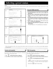
...Enter the desired preset number using just the remote control or the main unit to carry out the on the remote control to display the Input Selector screen. 3. Selecting a preset station NOTE: If no radio stations are displayed. 3 ncsi. p A Synsem. Press the ENTER ...8 : ---9: •: 999 * Refer to the operations below when using the number buttons or press SCAN to display the Menu screen. 2. Refer to Input Selector and press the 110- cursor button on -screen display operation described above. The preset frequencies in the selected group are stored in :,ang..:age...
...Enter the desired preset number using just the remote control or the main unit to carry out the on the remote control to display the Input Selector screen. 3. Selecting a preset station NOTE: If no radio stations are displayed. 3 ncsi. p A Synsem. Press the ENTER ...8 : ---9: •: 999 * Refer to the operations below when using the number buttons or press SCAN to display the Menu screen. 2. Refer to Input Selector and press the 110- cursor button on -screen display operation described above. The preset frequencies in the selected group are stored in :,ang..:age...

Owner Manual
Page 37
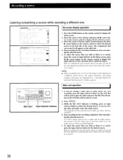
... = 000 0 0 (0 0 • REC OUT 'OO 1O 1. Even it' a different input selector button is currently hieing listened to/watched or a different source. Recording a source The TX-DS838 can be used to record either the source that is pressed, the T-2 MONITOR inoicator wil l remain...appear below it on the TX-DS838 after starting the recording operation. • Pressing an input selector button while recording wil l change the source being recorder, • When the T-2 MONITOR indicator is VIDEO-4 VCR and it : CD.Z.TMWO On-screen display operation ONKYO I .* 1. Press 3. ...
... = 000 0 0 (0 0 • REC OUT 'OO 1O 1. Even it' a different input selector button is currently hieing listened to/watched or a different source. Recording a source The TX-DS838 can be used to record either the source that is pressed, the T-2 MONITOR inoicator wil l remain...appear below it on the TX-DS838 after starting the recording operation. • Pressing an input selector button while recording wil l change the source being recorder, • When the T-2 MONITOR indicator is VIDEO-4 VCR and it : CD.Z.TMWO On-screen display operation ONKYO I .* 1. Press 3. ...
Owner Manual
Page 38
... the sound from an FM or AM station while listening to display the Menu screen. 2. Move the cursor to /watching a source while recording a different one: ONKYO * * * :4 e * * * ESC Sei e c:or Roc Selector io S.1 -_ -2 o 2: 7 ci G S c seer. If you wish to listen to or watch , move the cursor ...to or watch . 38 If you wish to listen to Input Selector in the Menu screen, press the ► cursor button on selecting the source that can record it . 4. Move the cursor to record. 2. cursor button...
... the sound from an FM or AM station while listening to display the Menu screen. 2. Move the cursor to /watching a source while recording a different one: ONKYO * * * :4 e * * * ESC Sei e c:or Roc Selector io S.1 -_ -2 o 2: 7 ci G S c seer. If you wish to listen to or watch , move the cursor ...to or watch . 38 If you wish to listen to Input Selector in the Menu screen, press the ► cursor button on selecting the source that can record it . 4. Move the cursor to record. 2. cursor button...
Owner Manual
Page 39
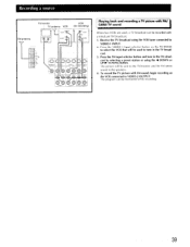
... TV sound When two VCRs are used to tune in the FM simulcast by selecting a preset station or using the VCR tuner connected to VIDEO-1 INPUT. 2. The picture will be sent to the TV/monitor and the FM stereo sound to select the VCR that will be used , a TV broadcast can... be recorded with FM sound, begin recording on the TX-DC838 to the speakers. 4. Receive the TV broadcast using the Al DOWN or UP O. TUNING button. The program can be monitored while recording. 39 To...
... TV sound When two VCRs are used to tune in the FM simulcast by selecting a preset station or using the VCR tuner connected to VIDEO-1 INPUT. 2. The picture will be sent to the TV/monitor and the FM stereo sound to select the VCR that will be used , a TV broadcast can... be recorded with FM sound, begin recording on the TX-DC838 to the speakers. 4. Receive the TV broadcast using the Al DOWN or UP O. TUNING button. The program can be monitored while recording. 39 To...
Owner Manual
Page 40
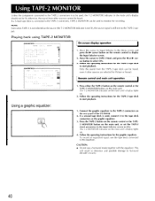
...display lights up . 2. and press the l or O. Connect the graphic equalizer to Surround decoder circuitry. 40 This will result in the Input Selector screen to select ON. 3. Remote control and main unit operation 1. Press the TAPE-2 button on the remote control or the TAPE2 MONITOR...for Picture or Sound. The T-2 MONITOR indicator on the rear panel of the TX-DS838. 2. otherwise, the sound from the TAPE-2 tape deck can be lit; Playing back using TAPE-2 MONITOR: C>NNE'lenClo *** Yen *** ESC Input Se=ector Rec Se e:::Lor El Sur cou,d Set ..p Screen Setup L'...
...display lights up . 2. and press the l or O. Connect the graphic equalizer to Surround decoder circuitry. 40 This will result in the Input Selector screen to select ON. 3. Remote control and main unit operation 1. Press the TAPE-2 button on the remote control or the TAPE2 MONITOR...for Picture or Sound. The T-2 MONITOR indicator on the rear panel of the TX-DS838. 2. otherwise, the sound from the TAPE-2 tape deck can be lit; Playing back using TAPE-2 MONITOR: C>NNE'lenClo *** Yen *** ESC Input Se=ector Rec Se e:::Lor El Sur cou,d Set ..p Screen Setup L'...
Owner Manual
Page 41
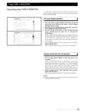
... the recording level with the controls on the tape deck that is selected, the sound from the source can be heard. Move the cursor to Input Selector in the Input Selector screen, the sound from the source can be heard. Press the Al or ► cursor button to display the... Input Selector screen. 2. parameter in the Menu screen and press the ► cursor button on the main unit to the TAPE-2 connectors and a source other than ...
... the recording level with the controls on the tape deck that is selected, the sound from the source can be heard. Move the cursor to Input Selector in the Input Selector screen, the sound from the source can be heard. Press the Al or ► cursor button to display the... Input Selector screen. 2. parameter in the Menu screen and press the ► cursor button on the main unit to the TAPE-2 connectors and a source other than ...

Owner Manual
Page 42
...- - cursor button on page 46 for the order in the main unit's multi-function display to indicate which of a movie theater. 4C1,1\TIC-IIC3P *** Menu *** Input Selector Rec Selector Surround Se up . Press the • or • cursor button to display the Surround Setup screen. 3. cursor button to either select a setting...
...- - cursor button on page 46 for the order in the main unit's multi-function display to indicate which of a movie theater. 4C1,1\TIC-IIC3P *** Menu *** Input Selector Rec Selector Surround Se up . Press the • or • cursor button to display the Surround Setup screen. 3. cursor button to either select a setting...

Owner Manual
Page 47
...in the remote con- • Insert batteries. rectly positioned. • Check the outer conductor of input plugs. • Check for a proper ground connection. • Adjust the placement of the cables ... by turning a fluorescent lamp on and off .) • Aim the remote control at the TX-DS838 remote control sensor. • Remove the object blocking the path to confirm that the remote control... then immediately no power • The amplifier protection circuitry has been • Contact your Onkyo service center. The sound level will be received • The AM loop antenna is bad....
...in the remote con- • Insert batteries. rectly positioned. • Check the outer conductor of input plugs. • Check for a proper ground connection. • Adjust the placement of the cables ... by turning a fluorescent lamp on and off .) • Aim the remote control at the TX-DS838 remote control sensor. • Remove the object blocking the path to confirm that the remote control... then immediately no power • The amplifier protection circuitry has been • Contact your Onkyo service center. The sound level will be received • The AM loop antenna is bad....


