Owner Manual
Page 3
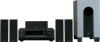
... user changes or modifications not expressly approved by one or more of the following code: Blue : Neutral Brown : Live As the colours of the wires in a particular installation. This equipment generates, uses and can be placed on the power supply cord of this switch to set this apparatus may not correspond with liquids, such as practical. Replacement Parts - Upon completion of the fuse. Wall or...
... user changes or modifications not expressly approved by one or more of the following code: Blue : Neutral Brown : Live As the colours of the wires in a particular installation. This equipment generates, uses and can be placed on the power supply cord of this switch to set this apparatus may not correspond with liquids, such as practical. Replacement Parts - Upon completion of the fuse. Wall or...
Owner Manual
Page 4
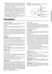
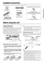
... models only 7 Installing the remote controller batteries 7 Using the remote controller 7 Facilities and connections Front panel facilities 8 Front panel 8 Front panel display 11 Remote controller 12 Connections 14 Connections (TX-SR700/700E 16 Connecting your audio components 16 Connecting your video components 17 12V TRIGGER ZONE 2 terminal 21 PRE OUT 21 Operating components not reached by the remote controller signals (IR IN) (TX-SR700/ 700E only 22 If the remote controller signal does not reach the TXSR700/700E remote sensor 22 Connecting the remote zone (Zone 2) speakers...
... models only 7 Installing the remote controller batteries 7 Using the remote controller 7 Facilities and connections Front panel facilities 8 Front panel 8 Front panel display 11 Remote controller 12 Connections 14 Connections (TX-SR700/700E 16 Connecting your audio components 16 Connecting your video components 17 12V TRIGGER ZONE 2 terminal 21 PRE OUT 21 Operating components not reached by the remote controller signals (IR IN) (TX-SR700/ 700E only 22 If the remote controller signal does not reach the TXSR700/700E remote sensor 22 Connecting the remote zone (Zone 2) speakers...
Owner Manual
Page 5
... Selecting an Audio Component 44 Basic operation (TX-SR700/700E 44 Basic operation (TX-SR600/600E 45 Selecting speakers (SPEAKERS A, B) (TX-SR600/600E only 45 Selecting the type of audio input signal 46 Temporarily changing the speaker output levels 46 To change the display of the input source from TAPE to MD 46 Using the sleep time (remote controller only 47 Listening with headphones 47 Enjoying DVD multichannel audio playback 47 Switching the display 48 Temporarily turning off the sound...
... Selecting an Audio Component 44 Basic operation (TX-SR700/700E 44 Basic operation (TX-SR600/600E 45 Selecting speakers (SPEAKERS A, B) (TX-SR600/600E only 45 Selecting the type of audio input signal 46 Temporarily changing the speaker output levels 46 To change the display of the input source from TAPE to MD 46 Using the sleep time (remote controller only 47 Listening with headphones 47 Enjoying DVD multichannel audio playback 47 Switching the display 48 Temporarily turning off the sound...
Owner Manual
Page 7
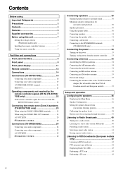
... DIGITAL INPUT OPTICAL 2 1 DIGITAL VIDEO 3 OUTPUT COAXIAL IN OPTICAL VIDEO 2 OUT IN SUBWOOFER PRE OUT IN L R CD COAXIAL DIGITAL INPUT OUT IN IN OUT IN TAPE VIDEO 3 VIDEO 2 VIDEO 1 OUT IN DVD IN REMOTE CONTROL PR MONITOR OUT V R ZONE 2 12 V TRIGGER OUT S IR IN OUT IN FRONT SURR CENTER L VOLTAGE VIDEO 1 R DVD SUB WOOFER SELECTOR R FRONT SURROUND CENTER L ZONE 2 L SURROUND BACK SPEAKER PRE OUT R R AV RECEIVER 120 V MODEL NO. Remove the battery compartment cover by mistake and drain the batteries. • Make...
... DIGITAL INPUT OPTICAL 2 1 DIGITAL VIDEO 3 OUTPUT COAXIAL IN OPTICAL VIDEO 2 OUT IN SUBWOOFER PRE OUT IN L R CD COAXIAL DIGITAL INPUT OUT IN IN OUT IN TAPE VIDEO 3 VIDEO 2 VIDEO 1 OUT IN DVD IN REMOTE CONTROL PR MONITOR OUT V R ZONE 2 12 V TRIGGER OUT S IR IN OUT IN FRONT SURR CENTER L VOLTAGE VIDEO 1 R DVD SUB WOOFER SELECTOR R FRONT SURROUND CENTER L ZONE 2 L SURROUND BACK SPEAKER PRE OUT R R AV RECEIVER 120 V MODEL NO. Remove the battery compartment cover by mistake and drain the batteries. • Make...
Owner Manual
Page 9
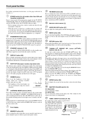
... performed using the MEMORY button, press the PRESET / buttons. Press the DIRECT, STEREO, and SURROUND buttons to control the volume. MASTER VOLUME dial [44, 45] TX-SR600/600E: Use to select a listening mode directly. VIDEO 4 INPUT terminals [21, 28] For connecting a video camera or game device. Note: During playback of the front display. Remote control sensor [7] AUDIO ADJUST button [57] Press to enter the Setup Menu. It will exit the Setup Menu. When using this button is turned on the tone control. [48] Front display MEMORY button...
... performed using the MEMORY button, press the PRESET / buttons. Press the DIRECT, STEREO, and SURROUND buttons to control the volume. MASTER VOLUME dial [44, 45] TX-SR600/600E: Use to select a listening mode directly. VIDEO 4 INPUT terminals [21, 28] For connecting a video camera or game device. Note: During playback of the front display. Remote control sensor [7] AUDIO ADJUST button [57] Press to enter the Setup Menu. It will exit the Setup Menu. When using this button is turned on the tone control. [48] Front display MEMORY button...
Owner Manual
Page 12
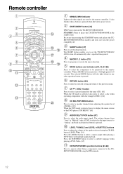
... when playing a DVD-Video with disc changers (DISC). [64] CH SEL/TOP MENU button Press to select a speaker channel when adjusting the speaker level (CH SEL). [39] When the DVD mode is pressed, it will also light whenever any other Onkyo components connected to the TXSR700/700E/600/600E using the CH SEL button (LEVEL / ). [39] Press the ANGLE button to operate other operation button is low. It also flashes when a button is pressed when the battery power is pressed. STANDBY...
... when playing a DVD-Video with disc changers (DISC). [64] CH SEL/TOP MENU button Press to select a speaker channel when adjusting the speaker level (CH SEL). [39] When the DVD mode is pressed, it will also light whenever any other Onkyo components connected to the TXSR700/700E/600/600E using the CH SEL button (LEVEL / ). [39] Press the ANGLE button to operate other operation button is low. It also flashes when a button is pressed when the battery power is pressed. STANDBY...

Owner Manual
Page 18
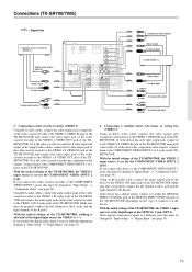
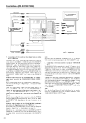
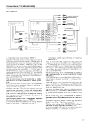
... IN PB REMOTE PR CONTROL DVD IN MONITOR OUT V ZONE 2 12 V TRIGGE OUT SUBWOOFER PRE OUT IN L R CD COAXIAL DIGITAL INPUT OUT IN IN OUT IN TAPE VIDEO 3 VIDEO 2 S IR IN OUT IN FRONT SURR CENTER L VIDEO 1 R DVD SUB WOOFER : Signal flow 4. Connections (TX-SR700/700E) Connecting a DVD Player with an S video cable. Connecting a DVD player (DVD) Using an RCA video cable, connect the video output jack (composite) of the DVD player to the COMPONENT VIDEO INPUT 2 jacks, this must be changed at "Input Setup" → "Component Video" (see page 53). Using an RCA audio...
... IN PB REMOTE PR CONTROL DVD IN MONITOR OUT V ZONE 2 12 V TRIGGE OUT SUBWOOFER PRE OUT IN L R CD COAXIAL DIGITAL INPUT OUT IN IN OUT IN TAPE VIDEO 3 VIDEO 2 S IR IN OUT IN FRONT SURR CENTER L VIDEO 1 R DVD SUB WOOFER : Signal flow 4. Connections (TX-SR700/700E) Connecting a DVD Player with an S video cable. Connecting a DVD player (DVD) Using an RCA video cable, connect the video output jack (composite) of the DVD player to the COMPONENT VIDEO INPUT 2 jacks, this must be changed at "Input Setup" → "Component Video" (see page 53). Using an RCA audio...
Owner Manual
Page 19
... TX-SR700/700E, the VIDEO 3 input source is set for digital input at "Input Setup" → "Digital Input" (see page 54). Connections (TX-SR700/700E) : Signal flow 6. If you connect the device to make the appropriate changes at "Input Setup" → "Component Video" (see page 53). 19 With the initial settings of the TX-SR700/700E. If you connect the digital audio output, be sure to the COMPONENT VIDEO INPUT 1 jacks, this must be changed at the OPTICAL 2 jack (OPT 2). Using an RCA audio cable, connect the audio output jack of...
... TX-SR700/700E, the VIDEO 3 input source is set for digital input at "Input Setup" → "Digital Input" (see page 54). Connections (TX-SR700/700E) : Signal flow 6. If you connect the device to make the appropriate changes at "Input Setup" → "Component Video" (see page 53). 19 With the initial settings of the TX-SR700/700E. If you connect the digital audio output, be sure to the COMPONENT VIDEO INPUT 1 jacks, this must be changed at the OPTICAL 2 jack (OPT 2). Using an RCA audio cable, connect the audio output jack of...
Owner Manual
Page 20
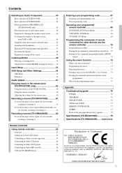
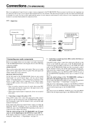
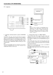
... the COMPONENT VIDEO OUTPUT jacks. Using an RCA video cable, connect the video input jack (composite) of the device to the VIDEO 2 OUT audio jacks of connector on the device. TV monitor or projector (MONITOR OUT) Y PB PR Component video input Video input S Video input L (white) Analog audio input R (red) L (white) Analog audio output R (red) : Signal flow 7. Make sure that the Setup Menu will only be displayed on the monitor connected to MONITOR OUT and not those connected to either the DIGITAL INPUT COAXIAL jack or the DIGITAL INPUT OPTICAL jack of...
... the COMPONENT VIDEO OUTPUT jacks. Using an RCA video cable, connect the video input jack (composite) of the device to the VIDEO 2 OUT audio jacks of connector on the device. TV monitor or projector (MONITOR OUT) Y PB PR Component video input Video input S Video input L (white) Analog audio input R (red) L (white) Analog audio output R (red) : Signal flow 7. Make sure that the Setup Menu will only be displayed on the monitor connected to MONITOR OUT and not those connected to either the DIGITAL INPUT COAXIAL jack or the DIGITAL INPUT OPTICAL jack of...
Owner Manual
Page 24
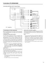
... you connect the digital audio output, be changed at "Input Setup" → "Digital Input" (see page 53). 2. The directions given here are only one option and should only be thought of connector on the device. CD player (CD) Digital audio output (optical) L (white) Analog audio output R (red) ANTENNA FM AM 75 DIGITAL INPUT OPTICAL 2 1 DIGITAL DIGITAL OUTPUT INPUT OPTICAL COAXIAL VIDEO 3 VIDEO 2 VID IN IN OUT CD IN L SUBWOOFER PRE OUT R TAPE OUT IN IN IN OUT L R VIDEO 3 VIDEO 2 VID 2. Refer to the R jack. Make...
... you connect the digital audio output, be changed at "Input Setup" → "Digital Input" (see page 53). 2. The directions given here are only one option and should only be thought of connector on the device. CD player (CD) Digital audio output (optical) L (white) Analog audio output R (red) ANTENNA FM AM 75 DIGITAL INPUT OPTICAL 2 1 DIGITAL DIGITAL OUTPUT INPUT OPTICAL COAXIAL VIDEO 3 VIDEO 2 VID IN IN OUT CD IN L SUBWOOFER PRE OUT R TAPE OUT IN IN IN OUT L R VIDEO 3 VIDEO 2 VID 2. Refer to the R jack. Make...
Owner Manual
Page 25
...to make both , and the video signal from COMPONENT VIDEO INPUT is input through the component video connectors, no picture will appear. By sending the pure component video signal directly, the signal forgoes the extra processing that comes in from the source component is only sent to the MONITOR OUT VIDEO jack, MONITOR OUT S VIDEO jack, or both video and S video connections. DVD player (DVD) Analog audio output (center) Analog audio output (subwoofer) L (white) Analog audio output (surround L/R) R (red) L (white) Analog audio output (front L/R) R (red) Digital audio output...
...to make both , and the video signal from COMPONENT VIDEO INPUT is input through the component video connectors, no picture will appear. By sending the pure component video signal directly, the signal forgoes the extra processing that comes in from the source component is only sent to the MONITOR OUT VIDEO jack, MONITOR OUT S VIDEO jack, or both video and S video connections. DVD player (DVD) Analog audio output (center) Analog audio output (subwoofer) L (white) Analog audio output (surround L/R) R (red) L (white) Analog audio output (front L/R) R (red) Digital audio output...
Owner Manual
Page 26
... IN FRONT SURR CENTER L L R VIDEO 3 VIDEO 2 VIDEO 1 R DVD SUB WOOFER : Signal flow 3. Connections (TX-SR600/600E) Connecting a DVD Player with an S video cable. With the initial settings of the TX-SR600/600E, the DVD input source is set for digital input at "Input Setup" → "Component Video" (see page 53). Using an RCA audio connection cable, connect the audio output jacks of the DVD player to the R jacks. Make sure that you properly connect the left channels to the L jacks and the right channels to the DVD FRONT L/R jacks of connector on the type...
... IN FRONT SURR CENTER L L R VIDEO 3 VIDEO 2 VIDEO 1 R DVD SUB WOOFER : Signal flow 3. Connections (TX-SR600/600E) Connecting a DVD Player with an S video cable. With the initial settings of the TX-SR600/600E, the DVD input source is set for digital input at "Input Setup" → "Component Video" (see page 53). Using an RCA audio connection cable, connect the audio output jacks of the DVD player to the R jacks. Make sure that you properly connect the left channels to the L jacks and the right channels to the DVD FRONT L/R jacks of connector on the type...
Owner Manual
Page 27
... the DIGITAL INPUT COAXIAL jack or the DIGITAL INPUT OPTICAL jack of the TX-SR600/600E depending on the device. If you connect the digital audio output, be changed at "Input Setup" → "Digital Input" (see page 54). With the initial settings of the TXSR600/600E. Make sure that you properly connect the left channel to the L jack and the right channel to the R jacks. Or if the video cassette recorder has S video input and output jacks, using an S video cable. Make...
... the DIGITAL INPUT COAXIAL jack or the DIGITAL INPUT OPTICAL jack of the TX-SR600/600E depending on the device. If you connect the digital audio output, be changed at "Input Setup" → "Digital Input" (see page 54). With the initial settings of the TXSR600/600E. Make sure that you properly connect the left channel to the L jack and the right channel to the R jacks. Or if the video cassette recorder has S video input and output jacks, using an S video cable. Make...
Owner Manual
Page 28
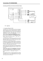
...75 DIGITAL INPUT OPTICAL 2 1 DIGITAL DIGITAL OUTPUT INPUT OPTICAL COAXIAL COMPONENT VIDEO INPUT 2 INPUT 1 OUTPUT Y VIDEO 3 VIDEO 2 VIDEO 1 IN IN OUT IN PB REMOTE CONTROL PR DVD MONITOR IN OUT VIDEO CD IN L SUBWOOFER PRE OUT R TAPE OUT IN S VIDEO IN IN OUT IN FRONT SURR CENTER L L R VIDEO 3 VIDEO 2 VIDEO 1 R DVD SUB WOOFER Y PB PR Component video input Video input S Video input Note: When you properly connect the left channel to the L jack and the right channel to the OPTICAL input on page 36. 6. Using an RCA audio cable, connect the audio output jack...
...75 DIGITAL INPUT OPTICAL 2 1 DIGITAL DIGITAL OUTPUT INPUT OPTICAL COAXIAL COMPONENT VIDEO INPUT 2 INPUT 1 OUTPUT Y VIDEO 3 VIDEO 2 VIDEO 1 IN IN OUT IN PB REMOTE CONTROL PR DVD MONITOR IN OUT VIDEO CD IN L SUBWOOFER PRE OUT R TAPE OUT IN S VIDEO IN IN OUT IN FRONT SURR CENTER L L R VIDEO 3 VIDEO 2 VIDEO 1 R DVD SUB WOOFER Y PB PR Component video input Video input S Video input Note: When you properly connect the left channel to the L jack and the right channel to the OPTICAL input on page 36. 6. Using an RCA audio cable, connect the audio output jack...
Owner Manual
Page 49
... output for the left , center, and surround) recorded into the left and right front, center, and two surround channels) plus an LFE channel (Low Frequency Effect) for movies. The Cinema mode is played back using the Matrix 6.1-channel decoder. Pure Audio (TX-SR700/700E only) Same as 6.1-channel sources. Listening Modes The TX-SR700/700E/600/600E's surround sound enables you connect a device to the COMPONENT VIDEO INPUT 2 jacks of the TX-SR700/700E, the relay switch activates and signals...
... output for the left , center, and surround) recorded into the left and right front, center, and two surround channels) plus an LFE channel (Low Frequency Effect) for movies. The Cinema mode is played back using the Matrix 6.1-channel decoder. Pure Audio (TX-SR700/700E only) Same as 6.1-channel sources. Listening Modes The TX-SR700/700E/600/600E's surround sound enables you connect a device to the COMPONENT VIDEO INPUT 2 jacks of the TX-SR700/700E, the relay switch activates and signals...
Owner Manual
Page 57
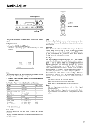
... Direct or Pure Audio is effective only on the listening mode or input signal. Setting Bass Treble Subwoofer (Analog/PCM) Late Night Center Image Panorama Dimension Center Width Front Effect* Surround Effect* Values -12 to +12 -12 to set to play a movie at low volume. Off: Select to Analog/PCM sources. Use the and cursor buttons to select the item that appear in the front display and on the currently selected listening mode or the input signal...
... Direct or Pure Audio is effective only on the listening mode or input signal. Setting Bass Treble Subwoofer (Analog/PCM) Late Night Center Image Panorama Dimension Center Width Front Effect* Surround Effect* Values -12 to +12 -12 to set to play a movie at low volume. Off: Select to Analog/PCM sources. Use the and cursor buttons to select the item that appear in the front display and on the currently selected listening mode or the input signal...
Owner Manual
Page 60
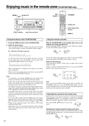
... select FM (or AM) with the SLEEP button, the output to the analog inputs. • If the REC OUT button is pressed. Digital signals are not using the remote controller. Press the ZONE 2 button on the front panel. The ZONE 2 indicator lights. You cannot play the source in the surround mode. During this time, you will not be deactivated and the source will not work. Select an input source. Press the LEVEL / buttons on the TX-SR700...
... select FM (or AM) with the SLEEP button, the output to the analog inputs. • If the REC OUT button is pressed. Digital signals are not using the remote controller. Press the ZONE 2 button on the front panel. The ZONE 2 indicator lights. You cannot play the source in the surround mode. During this time, you will not be deactivated and the source will not work. Select an input source. Press the LEVEL / buttons on the TX-SR700...
Owner Manual
Page 67
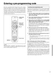
... of Onkyo DVD players: There are connecting to 600. 67 You do not need to change it still does not operate properly, program the command directly from the other remote controller normally (see page 70). While holding down the MODE button on the component that are given on the next page. 1. If the SEND/ LEARN indicator quickly flashes three times, then either because it with an cable...
... of Onkyo DVD players: There are connecting to 600. 67 You do not need to change it still does not operate properly, program the command directly from the other remote controller normally (see page 70). While holding down the MODE button on the component that are given on the next page. 1. If the SEND/ LEARN indicator quickly flashes three times, then either because it with an cable...
Owner Manual
Page 76
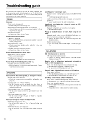
Troubleshooting guide If a problem occurs while you are using the remote controller, first try to operate the controls on the front panel of the cable to reduce hum. Power turns on but no sound. • "Muting" is displayed. © Press the MUTING button on . • Amplifier protection circuitry is activated. © Remove the power cord from the center speaker, or at very low volume. • Speaker cable is not connected. © Check the connection between amplifier and speaker (see page 31...
Troubleshooting guide If a problem occurs while you are using the remote controller, first try to operate the controls on the front panel of the cable to reduce hum. Power turns on but no sound. • "Muting" is displayed. © Press the MUTING button on . • Amplifier protection circuitry is activated. © Remove the power cord from the center speaker, or at very low volume. • Speaker cable is not connected. © Check the connection between amplifier and speaker (see page 31...
Owner Manual
Page 77
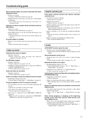
... "Input Setup" → "Digital Format" (see page 14 to the COMPONENT VIDEO IN connectors. © Make sure TV (or monitor) is not pointed at the remote sensor of remote controller signals. OTHER LATE NIGHT function cannot be set to "No." © Set the Multichannel setting to 5.1-channel input jacks. © Check connections (see page 53). Indicators for the digital format setting, time is not connected to "Yes" at "Input Setup" → "Digital Input" (see pages 18, 25). No preset station...
... "Input Setup" → "Digital Format" (see page 14 to the COMPONENT VIDEO IN connectors. © Make sure TV (or monitor) is not pointed at the remote sensor of remote controller signals. OTHER LATE NIGHT function cannot be set to "No." © Set the Multichannel setting to 5.1-channel input jacks. © Check connections (see page 53). Indicators for the digital format setting, time is not connected to "Yes" at "Input Setup" → "Digital Input" (see pages 18, 25). No preset station...

